3/21/24
AIM
FIG 4
−
3
−
20
Flagman Directs Pilot
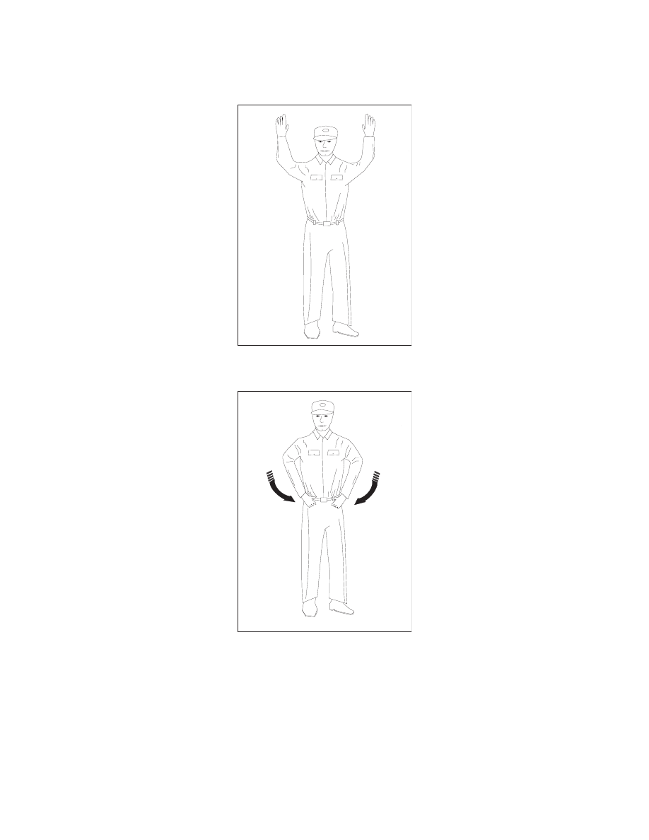
FIG 4
−
3
−
21
Insert Chocks
Airport Operations
4
−
3
−
35