AIM
4/20/23
FIG 6
−
5
−
2
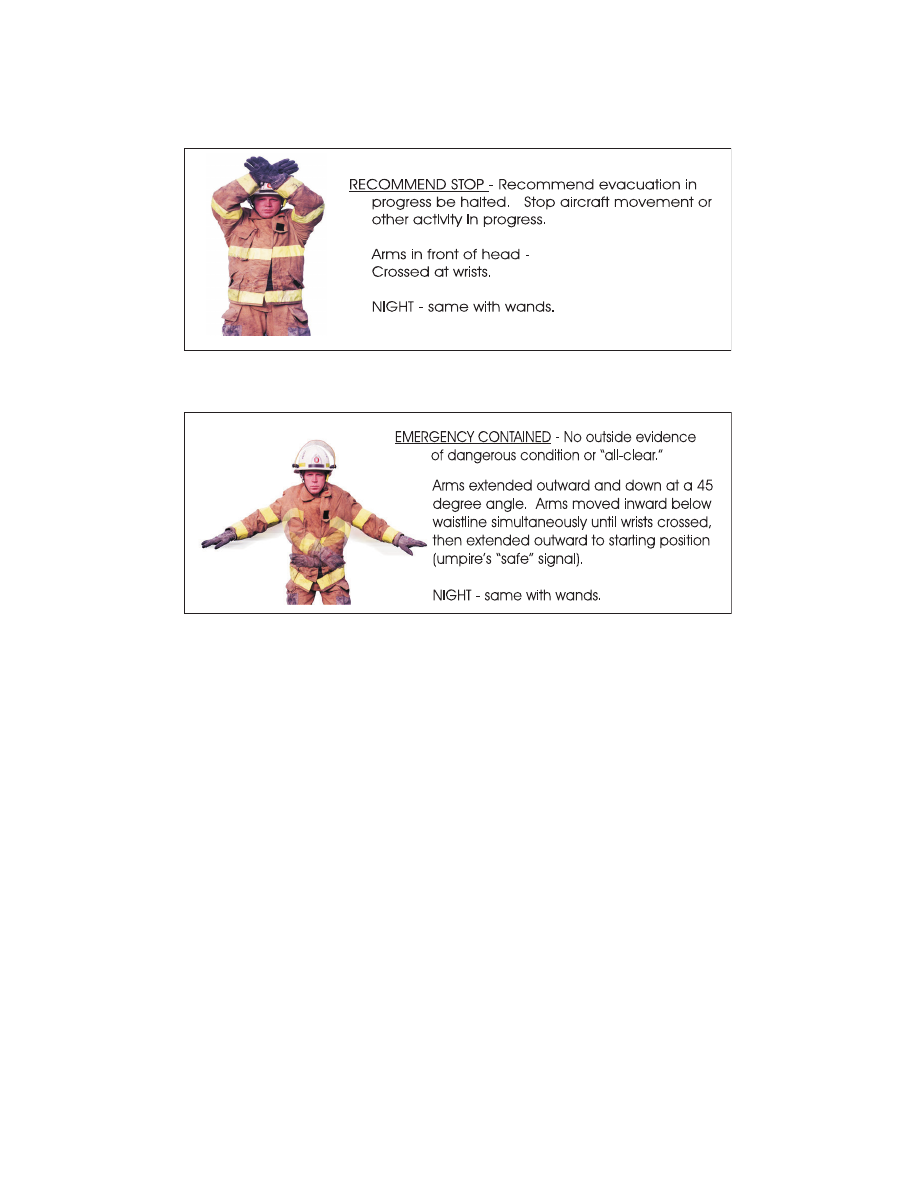
Recommend Stop
FIG 6
−
5
−
3
Emergency Contained
6
−
5
−
2
Aircraft Rescue and Fire Fighting Communications
AIM
4/20/23
FIG 6
−
5
−
2
Recommend Stop
FIG 6
−
5
−
3
Emergency Contained
6
−
5
−
2
Aircraft Rescue and Fire Fighting Communications