4/20/23
AIM
FIG 1
−
1
−
1
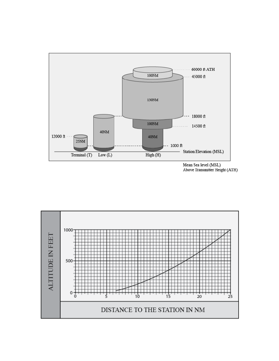
Original Standard Service Volumes
FIG 1
−
1
−
2
Lower Edge of the Terminal Service Volume (in altitude ATH)
Navigation Aids
1
−
1
−
7
4/20/23
AIM
FIG 1
−
1
−
1
Original Standard Service Volumes
FIG 1
−
1
−
2
Lower Edge of the Terminal Service Volume (in altitude ATH)
Navigation Aids
1
−
1
−
7