854
14 CFR Ch. I (1–1–24 Edition)
§ 171.311
Wind Velocity: The ground equipment shall
remain within monitor limits with wind
velocities of up to 70 knots from such di-
rections that the velocity component
perpendicular to runway centerline does
not exceed 35 knots. The ground equip-
ment shall withstand winds up to 100
knots from any direction without dam-
age.
Hail Stones: 1.25 centimeters (
1
⁄
2
inch) diame-
ter.
Rain: Provide required coverage with rain
falling at a rate of 50 millimeters (2
inches) per hour, through a distance of 9
kilometers (5 nautical miles) and with
rain falling at the rate of 25 millimeters
(1 inch) per hour for the additional 28 kil-
ometers (15 nautical miles).
Ice Loading: Encased in 1.25 centimeters (
1
⁄
2
inch) radial thickness of clear ice.
Antenna Radome De-Icing: Down to
¥
6
°
C (20
°
F) and wind up to 35 knots.
(d) The transmitter frequencies of an
MLS must be in accordance with the
frequency plan approved by the FAA.
(e) The DME component listed in
paragraph (a)(4) of this section must
comply with the minimum standard
performance requirements specified in
subpart G of this part.
(f) The marker beacon components
listed in paragraph (b)(4) of this section
must comply with the minimum stand-
ard performance requirements specified
in subpart H of this part.
§ 171.311 Signal format requirements.
The signals radiated by the MLS
must conform to the signal format in
which angle guidance functions and
data functions are transmitted sequen-
tially on the same C-band frequency.
Each function is identified by a unique
digital code which initializes the air-
borne receiver for proper processing.
The signal format must meet the fol-
lowing minimum requirements:
(a)
Frequency assignment.
The ground
components (except DME/Marker Bea-
con) must operate on a single fre-
quency assignment or channel, using
time division multiplexing. These com-
ponents must be capable of operating
on any one of the 200 channels spaced
300 KHz apart with center frequencies
from 5031.0 MHz to 5090.7 MHz and with
channel numbering as shown in Table
1a. The operating radio frequencies of
all ground components must not vary
by more than
±
10 KHz from the as-
signed frequency. Any one transmitter
frequency must not vary more than
±
50
Hz in any one second period. The MLS
angle/data and DME equipment must
operate on one of the paired channels
as shown in Table 1b.
T
ABLE
1a—F
REQUENCY
C
HANNEL
P
LAN
Channel No.
Fre-
quency
(MHz)
500 ...........................................................................
5031.0
501 ...........................................................................
5031.3
502 ...........................................................................
5031.6
503 ...........................................................................
5031.9
504 ...........................................................................
5032.2
505 ...........................................................................
5032.5
506 ...........................................................................
5032.8
507 ...........................................................................
5033.1
508 ...........................................................................
5033.4
509 ...........................................................................
5033.7
510 ...........................................................................
5034.0
511 ...........................................................................
5034.3
*
*
*
*
*
598 ...........................................................................
5060.4
599 ...........................................................................
5060.7
600 ...........................................................................
5061.0
601 ...........................................................................
5061.3
*
*
*
*
*
698 ...........................................................................
5090.4
699 ...........................................................................
5090.7
T
ABLE
1b—C
HANNELS
Channel pairing
DME parameters
DME No.
VHF freq.
MHz
MLS angle
freq. MHz
MLS Ch.
No.
Interrogation
Reply
Freq.
MHz
Pulse codes
Freq.
MHz
Pulse codes
µ
s
DME/N
µ
s
DME/P Mode
IA
µ
s
FA
µ
s
* 1X ....................
....................
....................
..............
1025
12 ..............
..............
962
12
** 1Y ..................
....................
....................
..............
1025
36 ..............
..............
1088
30
* 2X ....................
....................
....................
..............
1026
12 ..............
..............
963
12
** 2Y ..................
....................
....................
..............
1026
36 ..............
..............
1089
30
* 3X ....................
....................
....................
..............
1027
12 ..............
..............
964
12
** 3Y ..................
....................
....................
..............
1027
36 ..............
..............
1090
30
* 4X ....................
....................
....................
..............
1028
12 ..............
..............
965
12
** 4Y ..................
....................
....................
..............
1028
36 ..............
..............
1091
30
* 5X ....................
....................
....................
..............
1029
12 ..............
..............
966
12

855
Federal Aviation Administration, DOT
§ 171.311
T
ABLE
1b—C
HANNELS
—Continued
Channel pairing
DME parameters
DME No.
VHF freq.
MHz
MLS angle
freq. MHz
MLS Ch.
No.
Interrogation
Reply
Freq.
MHz
Pulse codes
Freq.
MHz
Pulse codes
µ
s
DME/N
µ
s
DME/P Mode
IA
µ
s
FA
µ
s
** 5Y ..................
....................
....................
..............
1029
36 ..............
..............
1092
30
* 6X ....................
....................
....................
..............
1030
12 ..............
..............
967
12
** 6Y ..................
....................
....................
..............
1030
36 ..............
..............
1093
30
* 7X ....................
....................
....................
..............
1031
12 ..............
..............
968
12
** 7Y ..................
....................
....................
..............
1031
36 ..............
..............
1094
30
* 8X ....................
....................
....................
..............
1032
12 ..............
..............
969
12
** 8Y ..................
....................
....................
..............
1032
36 ..............
..............
1095
30
* 9X ....................
....................
....................
..............
1033
12 ..............
..............
970
12
** 9Y ..................
....................
....................
..............
1033
36 ..............
..............
1096
30
* 10X ..................
....................
....................
..............
1034
12 ..............
..............
971
12
** 10Y ................
....................
....................
..............
1034
36 ..............
..............
1097
30
* 11X ..................
....................
....................
..............
1035
12 ..............
..............
972
12
** 11Y ................
....................
....................
..............
1035
36 ..............
..............
1098
30
* 12X ..................
....................
....................
..............
1036
12 ..............
..............
973
12
** 12Y ................
....................
....................
..............
1036
36 ..............
..............
1099
30
* 13X ..................
....................
....................
..............
1037
12 ..............
..............
974
12
** 13Y ................
....................
....................
..............
1037
36 ..............
..............
1100
30
* 14X ..................
....................
....................
..............
1038
12 ..............
..............
975
12
** 14Y ................
....................
....................
..............
1038
36 ..............
..............
1101
30
* 15X ..................
....................
....................
..............
1039
12 ..............
..............
976
12
** 15Y ................
....................
....................
..............
1039
36 ..............
..............
1102
30
* 16X ..................
....................
....................
..............
1040
12 ..............
..............
977
12
** 16Y ................
....................
....................
..............
1040
36 ..............
..............
1103
30
S
17X .................
108.00 ....................
..............
1041
12 ..............
..............
978
12
17Y ....................
108.05
5043.0
540
1041
36
36
42
1104
30
17Z ....................
....................
5043.3
541
1041 ..............
21
27
1104
15
18X ....................
108.10
5031.0
500
1042
12
12
18
979
12
18W ...................
....................
5031.3
501
1042 ..............
24
30
979
24
18Y ....................
108.15
5043.6
542
1042
36
36
42
1105
30
18Z ....................
....................
5043.9
543
1042 ..............
21
27
1105
15
19X ....................
108.20 ....................
..............
1043
12 ..............
..............
980
12
19Y ....................
108.25
5044.2
544
1043
36
36
42
1106
30
19Z ....................
....................
5044.5
545
1043 ..............
21
27
1106
15
20X ....................
108.30
5031.6
502
1044
12
12
18
981
12
20W ...................
....................
5031.9
503
1044 ..............
24
30
981
24
20Y ....................
108.35
5044.8
546
1044
36
36
42
1107
30
20Z ....................
....................
5045.1
547
1044 ..............
21
27
1107
15
21X ....................
108.40 ....................
..............
1045
12 ..............
..............
982
12
21Y ....................
108.45
5045.4
548
1045
36
36
42
1108
30
21Z ....................
....................
5045.7
549
1045 ..............
21
27
1108
15
22X ....................
108.50
5032.2
504
1046
12
12
18
983
12
22W ...................
....................
5032.5
505
1046 ..............
24
30
983
24
22Y ....................
108.55
5046.0
550
1046
36
36
42
1109
30
22Z ....................
....................
5046.3
551
1046 ..............
21
27
1109
15
23X ....................
108.60 ....................
..............
1047
12 ..............
..............
984
12
23Y ....................
108.65
5046.6
552
1047
36
36
42
1110
30
23Z ....................
....................
5046.9
553
1047 ..............
21
27
1110
15
24X ....................
108.70
5032.8
506
1048
12
12
18
985
12
24W ...................
....................
5033.1
507
1048 ..............
24
30
985
24
24Y ....................
108.75
5047.2
554
1048
36
36
42
1111
30
24Z ....................
....................
5047.5
555
1048 ..............
21
27
1111
15
25X ....................
108.80 ....................
..............
1049
12 ..............
..............
986
12
25Y ....................
108.85
5047.8
556
1049
36
36
42
1112
30
25Z ....................
....................
5048.1
557
1049 ..............
21
27
1112
15
26X ....................
108.90
5033.4
508
1050
12
12
18
987
12
26W ...................
....................
5033.7
509
1050 ..............
24
30
987
24
26Y ....................
108.95
5048.4
558
1050
36
36
42
1113
30
26Z ....................
....................
5048.7
559
1050 ..............
21
27
1113
15
27X ....................
109.00 ....................
..............
1051
12 ..............
..............
988
12
27Y ....................
109.05
5049.0
560
1051
36
36
42
1114
30
27Z ....................
....................
5049.3
561
1051 ..............
21
27
1114
15
28X ....................
109.10
5034.0
510
1052
12
12
18
989
12
28W ...................
....................
5034.3
511
1052 ..............
24
30
989
24
28Y ....................
109.15
5049.6
562
1052
36
36
42
1115
30
28Z ....................
....................
5049.9
563
1052 ..............
21
27
1115
15

856
14 CFR Ch. I (1–1–24 Edition)
§ 171.311
T
ABLE
1b—C
HANNELS
—Continued
Channel pairing
DME parameters
DME No.
VHF freq.
MHz
MLS angle
freq. MHz
MLS Ch.
No.
Interrogation
Reply
Freq.
MHz
Pulse codes
Freq.
MHz
Pulse codes
µ
s
DME/N
µ
s
DME/P Mode
IA
µ
s
FA
µ
s
29X ....................
109.20 ....................
..............
1053
12 ..............
..............
990
12
29Y ....................
109.25
5050.2
564
1053
36
36
42
1116
30
29Z ....................
....................
5050.5
565
1043 ..............
21
27
1116
15
30X ....................
109.30
5034.6
512
1054
12
12
18
991
12
30W ...................
....................
5034.9
513
1054 ..............
24
30
991
24
30Y ....................
109.35
5050.8
566
1054
36
36
42
1117
30
30Z ....................
....................
5051.1
567
1054 ..............
21
27
1117
15
31X ....................
109.40 ....................
..............
1055
12 ..............
..............
992
12
31Y ....................
109.45
5051.4
568
1055
36
36
42
1118
30
31Z ....................
....................
5051.7
569
1055 ..............
21
27
1118
15
32X ....................
109.50
5035.2
514
1056
12
12
18
993
12
32W ...................
....................
5035.5
515
1056 ..............
24
30
993
24
32Y ....................
109.55
5052.0
570
1056
36
36
42
1119
30
32Z ....................
....................
5052.3
571
1056 ..............
21
27
1119
15
33X ....................
109.60 ....................
..............
1057
12 ..............
..............
994
12
33Y ....................
109.65
5052.6
572
1057
36
36
42
1120
30
33Z ....................
....................
5052.9
573
1057 ..............
21
27
1120
15
34X ....................
109.70
5035.8
516
1058
12
12
18
995
12
34W ...................
....................
5036.1
517
1058 ..............
24
30
995
24
34Y ....................
109.75
5053.2
574
1058
36
36
42
1121
30
34Z ....................
....................
5053.5
575
1058 ..............
21
27
1121
15
35X ....................
109.80 ....................
..............
1059
12 ..............
..............
996
12
35Y ....................
109.85
5053.8
576
1059
36
36
42
1122
30
35Z ....................
....................
5054.1
577
1059 ..............
21
27
1122
15
36X ....................
109.90
5036.4
518
1060
12
12
18
997
12
36W ...................
....................
5036.7
519
1060 ..............
24
30
997
24
36Y ....................
109.95
5054.4
578
1060
36
36
42
1123
30
36Z ....................
....................
5054.7
579
1060 ..............
21
27
1123
15
37X ....................
110.00 ....................
..............
1061
12 ..............
..............
998
12
37Y ....................
110.05
5055.0
580
1061
36
36
42
1124
30
37Z ....................
....................
5055.3
581
1061 ..............
21
27
1124
15
38X ....................
110.10
5037.0
520
1062
12
12
18
999
12
38W ...................
....................
5037.3
521
1062 ..............
24
30
999
24
38Y ....................
110.15
5055.6
582
1062
36
36
42
1125
30
38Z ....................
....................
5055.9
583
1062 ..............
21
27
1125
15
39X ....................
110.20 ....................
..............
1063
12 ..............
..............
1000
12
39Y ....................
110.25
5056.2
584
1063
36
36
42
1126
30
39Z ....................
....................
5056.5
585
1063 ..............
21
27
1126
15
40X ....................
110.30
5037.6
522
1064
12
12
18
1001
12
40W ...................
....................
5037.9
523
1064 ..............
24
30
1001
24
40Y ....................
110.35
5056.8
586
1064
36
36
42
1127
30
40Z ....................
....................
5057.1
587
1064 ..............
21
27
1127
15
41X ....................
110.40 ....................
..............
1065
12 ..............
..............
1002
12
41Y ....................
110.45
5057.4
588
1065
36
36
42
1128
30
41Z ....................
....................
5057.7
589
1065 ..............
21
27
1128
15
42X ....................
110.50
5038.2
524
1066
12
12
18
1003
12
42W ...................
....................
5038.5
525
1066 ..............
24
30
1003
24
42Y ....................
110.55
5058.0
590
1066
36
36
42
1129
30
42Z ....................
....................
5058.3
591
1066 ..............
21
27
1129
15
43X ....................
110.60 ....................
..............
1067
12 ..............
..............
1004
12
43Y ....................
110.65
5058.6
592
1067
36
36
42
1130
30
43Z ....................
....................
5058.9
593
1067 ..............
21
27
1130
15
44X ....................
110.70
5038.8
526
1068
12
12
18
1005
12
44W ...................
....................
5039.1
527
1068 ..............
24
30
1005
24
44Y ....................
110.75
5059.2
594
1068
36
36
42
1131
30
44Z ....................
....................
5059.5
595
1068 ..............
21
27
1131
15
45X ....................
110.80 ....................
..............
1069
12 ..............
..............
1006
12
45Y ....................
110.85
5059.8
596
1069
36
36
42
1132
30
45Z ....................
....................
5060.1
597
1069 ..............
21
27
1132
15
46X ....................
110.90
5039.4
528
1070
12
12
18
1007
12
46W ...................
....................
5039.7
529
1070 ..............
24
30
1007
24
46Y ....................
110.95
5060.4
598
1070
36
36
42
1133
30
46Z ....................
....................
5060.7
599
1070 ..............
21
27
1133
15
47X ....................
111.00 ....................
..............
1071
12 ..............
..............
1008
12
47Y ....................
111.05
5061.0
600
1071
36
36
42
1134
30

857
Federal Aviation Administration, DOT
§ 171.311
T
ABLE
1b—C
HANNELS
—Continued
Channel pairing
DME parameters
DME No.
VHF freq.
MHz
MLS angle
freq. MHz
MLS Ch.
No.
Interrogation
Reply
Freq.
MHz
Pulse codes
Freq.
MHz
Pulse codes
µ
s
DME/N
µ
s
DME/P Mode
IA
µ
s
FA
µ
s
47Z ....................
....................
5061.3
601
1071 ..............
21
27
1134
15
48X ....................
111.10
5040.0
530
1072
12
12
18
1009
12
48W ...................
....................
5040.3
531
1072 ..............
24
30
1009
24
48Y ....................
111.15
5061.6
602
1072
36
36
42
1135
30
48Z ....................
....................
5061.9
603
1072 ..............
21
27
1135
15
49X ....................
111.20 ....................
..............
1073
12 ..............
..............
1010
12
49Y ....................
111.25
5062.2
604
1073
36
36
42
1136
30
49Z ....................
....................
5062.5
605
1073 ..............
21
27
1136
15
50X ....................
111.30
5040.6
532
1074
12
12
18
1011
12
50W ...................
....................
5040.9
533
1074 ..............
24
30
1011
24
50Y ....................
111.35
5062.8
606
1074
36
36
42
1137
30
50Z ....................
....................
5063.1
607
1074 ..............
21
27
1137
15
51X ....................
111.40 ....................
..............
1075
12 ..............
..............
1012
12
51Y ....................
111.45
5063.4
608
1075
36
36
42
1138
30
51Z ....................
....................
5063.7
609
1075 ..............
21
27
1138
15
52X ....................
111.50
5041.2
534
1076
12
12
18
1013
12
52W ...................
....................
5041.5
535
1076 ..............
24
30
1013
24
52Y ....................
111.55
5064.0
610
1076
36
36
42
1139
30
52Z ....................
....................
5064.3
611
1076 ..............
21
27
1139
15
53X ....................
111.60 ....................
..............
1077
12 ..............
..............
1014
12
53Y ....................
111.65
5064.6
612
1077
36
36
42
1140
30
53Z ....................
....................
5064.9
613
1077 ..............
21
27
1140
15
54X ....................
111.70
5041.8
536
1078
12
12
18
1015
12
54W ...................
....................
5042.1
537
1078 ..............
24
30
1015
24
54Y ....................
111.75
5065.2
614
1078
36
36
42
1141
30
54Z ....................
....................
5065.5
615
1078 ..............
21
27
1141
15
55X ....................
111.80 ....................
..............
1079
12 ..............
..............
1016
12
55Y ....................
111.85
5065.8
616
1079
36
36
42
1142
30
55Z ....................
....................
5066.1
617
1079 ..............
21
27
1142
15
56X ....................
111.90
5042.4
538
1080
12
12
18
1017
12
56W ...................
....................
5042.7
539
1080 ..............
24
30
1017
24
56Y ....................
111.95
5066.4
618
1080
36
36
42
1143
30
56Z ....................
....................
5066.7
619
1080 ..............
21
27
1143
15
57X ....................
112.00 ....................
..............
1081
12 ..............
..............
1018
12
57Y ....................
112.05 ....................
..............
1081
36 ..............
..............
1144
30
58X ....................
112.10 ....................
..............
1082
12 ..............
..............
1019
12
58Y ....................
112.15 ....................
..............
1082
36 ..............
..............
1145
30
59X ....................
112.20 ....................
..............
1083
12 ..............
..............
1020
12
59Y ....................
122.25 ....................
..............
1083
36 ..............
..............
1146
30
** 60X ................
....................
....................
..............
1084
12 ..............
..............
1021
12
** 60Y ................
....................
....................
..............
1084
36 ..............
..............
1147
30
** 61X ................
....................
....................
..............
1085
12 ..............
..............
1022
12
** 61Y ................
....................
....................
..............
1085
36 ..............
..............
1148
30
** 62X ................
....................
....................
..............
1086
12 ..............
..............
1023
12
** 62Y ................
....................
....................
..............
1086
36 ..............
..............
1149
30
** 63X ................
....................
....................
..............
1037
12 ..............
..............
1024
12
** 63Y ................
....................
....................
..............
1087
36 ..............
..............
1150
30
** 64X ................
....................
....................
..............
1088
12 ..............
..............
1151
12
** 64Y ................
....................
....................
..............
1088
36 ..............
..............
1025
30
** 65X ................
....................
....................
..............
1089
12 ..............
..............
1152
12
** 65Y ................
....................
....................
..............
1089
36 ..............
..............
1026
30
** 66X ................
....................
....................
..............
1090
12 ..............
..............
1153
12
** 66Y ................
....................
....................
..............
1090
36 ..............
..............
1027
30
** 67X ................
....................
....................
..............
1091
12 ..............
..............
1154
12
** 67Y ................
....................
....................
..............
1091
36 ..............
..............
1028
30
** 68X ................
....................
....................
..............
1092
12 ..............
..............
1155
12
** 68Y ................
....................
....................
..............
1092
36 ..............
..............
1029
30
** 69X ................
....................
....................
..............
1093
12 ..............
..............
1156
12
** 69Y ................
....................
....................
..............
1093
36 ..............
..............
1030
30
70X ....................
112.30 ....................
..............
1094
12 ..............
..............
1157
12
** 70Y ................
112.35 ....................
..............
1094
36 ..............
..............
1031
30
71X ....................
112.40 ....................
..............
1095
12 ..............
..............
1158
12
** 71Y ................
112.45 ....................
..............
1095
36 ..............
..............
1032
30
72X ....................
112.50 ....................
..............
1096
12 ..............
..............
1159
12
** 72Y ................
112.55 ....................
..............
1096
36 ..............
..............
1033
30
858
14 CFR Ch. I (1–1–24 Edition)
§ 171.311
T
ABLE
1b—C
HANNELS
—Continued
Channel pairing
DME parameters
DME No.
VHF freq.
MHz
MLS angle
freq. MHz
MLS Ch.
No.
Interrogation
Reply
Freq.
MHz
Pulse codes
Freq.
MHz
Pulse codes
µ
s
DME/N
µ
s
DME/P Mode
IA
µ
s
FA
µ
s
73X ....................
112.60 ....................
..............
1097
12 ..............
..............
1160
12
** 73Y ................
112.65 ....................
..............
1097
36 ..............
..............
1034
30
74X ....................
112.70 ....................
..............
1098
12 ..............
..............
1161
12
** 74Y ................
112.75 ....................
..............
1098
36 ..............
..............
1035
30
75X ....................
112.80 ....................
..............
1099
12 ..............
..............
1162
12
** 75Y ................
112.85 ....................
..............
1099
36 ..............
..............
1036
30
76X ....................
112.90 ....................
..............
1100
12 ..............
..............
1163
12
** 76Y ................
112.95 ....................
..............
1100
36 ..............
..............
1037
30
77X ....................
113.00 ....................
..............
1101
12 ..............
..............
1164
12
** 77Y ................
113.05 ....................
..............
1101
36 ..............
..............
1038
30
78X ....................
113.10 ....................
..............
1102
12 ..............
..............
1165
12
** 78Y ................
113.15 ....................
..............
1102
36 ..............
..............
1039
30
79X ....................
113.20 ....................
..............
1103
12 ..............
..............
1166
12
** 79Y ................
113.25 ....................
..............
1103
36 ..............
..............
1040
30
80X ....................
113.30 ....................
..............
1104
12 ..............
..............
1167
12
80Y ....................
113.35
5067.0
620
1104
36
36
42
1041
30
80Z ....................
....................
5067.3
621
1104 ..............
21
27
1041
15
81X ....................
113.40 ....................
..............
1105
12 ..............
..............
1168
12
81Y ....................
113.45
5067.6
622
1105
36
36
42
1042
30
81Z ....................
....................
5067.9
623
1005 ..............
21
27
1042
15
82X ....................
113.50 ....................
..............
1106
12 ..............
..............
1169
12
82Y ....................
113.55
5068.2
624
1106
36
36
42
1043
30
82Z ....................
....................
5068.5
625
1106 ..............
21
27
1043
15
83X ....................
113.60 ....................
..............
1107
12 ..............
..............
1170
12
83Y ....................
113.65
5068.8
626
1107
36
36
42
1044
30
83Z ....................
....................
5069.1
627
1107 ..............
21
27
1044
15
84X ....................
113.70 ....................
..............
1108
12 ..............
..............
1171
12
84Y ....................
113.75
5069.4
628
1108
36
36
42
1045
30
84Z ....................
....................
6069.7
629
1108 ..............
21
27
1045
15
85X ....................
113.80 ....................
..............
1109
12 ..............
..............
1172
12
85Y ....................
113.85
5070.0
630
1109
36
36
42
1046
30
85Z ....................
....................
5070.3
631
1109 ..............
21
27
1046
15
86X ....................
113.90 ....................
..............
1110
12 ..............
..............
1173
12
86Y ....................
113.95
5070.6
632
1110
36
36
42
1047
30
86Z ....................
....................
5070.9
633
1110 ..............
21
27
1047
15
87X ....................
114.00 ....................
..............
1111
12 ..............
..............
1174
12
87Y ....................
114.05
5071.2
634
1111
36
36
42
1048
30
87Z ....................
....................
5071.5
635
1111 ..............
21
27
1048
15
88X ....................
114.10 ....................
..............
1112
12 ..............
..............
1175
12
88Y ....................
114.15
5071.8
636
1112
36
36
42
1049
30
88Z ....................
....................
5072.1
637
1112 ..............
21
27
1049
15
89X ....................
114.20 ....................
..............
1113
12 ..............
..............
1176
12
89Y ....................
114.25
5072.4
638
1113
36
36
42
1050
30
89Z ....................
....................
5072.7
639
1113 ..............
21
27
1050
15
90X ....................
114.30 ....................
..............
1114
12 ..............
..............
1177
12
90Y ....................
114.35
5073.0
640
1114
36
36
42
1051
30
90Z ....................
....................
5073.3
641
1114 ..............
21
27
1051
15
91X ....................
114.40 ....................
..............
1115
12 ..............
..............
1178
12
91Y ....................
114.45
5073.6
642
1115
36
36
42
1052
30
91Z ....................
....................
5073.9
643
1115 ..............
21
27
1052
15
92X ....................
114.50 ....................
..............
1116
12 ..............
..............
1179
12
92Y ....................
114.55
5074.2
644
1116
36
36
42
1053
30
92Z ....................
....................
5074.5
645
1116 ..............
21
27
1053
15
93X ....................
114.60 ....................
..............
1117
12 ..............
..............
1180
12
93Y ....................
114.65
5074.8
646
1117
36
36
42
1054
30
93Z ....................
....................
5075.1
647
1117 ..............
21
27
1054
15
94X ....................
114.70 ....................
..............
1118
12 ..............
..............
1181
12
94Y ....................
114.75
5075.4
648
1118
36
36
42
1055
30
94Z ....................
....................
5075.7
649
1118 ..............
21
27
1055
15
95X ....................
114.80 ....................
..............
1119
12 ..............
..............
1182
12
95Y ....................
114.85
5076.0
650
1119
36
36
42
1056
30
95Z ....................
....................
5076.3
651
1119 ..............
21
27
1056
15
96X ....................
114.90 ....................
..............
1120
12 ..............
..............
1183
12
96Y ....................
114.95
5076.6
652
1120
36
36
42
1057
30
96Z ....................
....................
5076.9
653
1120 ..............
21
27
1057
15

859
Federal Aviation Administration, DOT
§ 171.311
T
ABLE
1b—C
HANNELS
—Continued
Channel pairing
DME parameters
DME No.
VHF freq.
MHz
MLS angle
freq. MHz
MLS Ch.
No.
Interrogation
Reply
Freq.
MHz
Pulse codes
Freq.
MHz
Pulse codes
µ
s
DME/N
µ
s
DME/P Mode
IA
µ
s
FA
µ
s
97X ....................
115.00 ....................
..............
1121
12 ..............
..............
1184
12
97Y ....................
115.05
5077.2
654
1121
36
36
42
1058
30
97Z ....................
....................
5077.5
655
1121 ..............
21
27
1058
15
98X ....................
115.10 ....................
..............
1122
12 ..............
..............
1185
12
98Y ....................
115.15
5077.8
656
1122
36
36
42
1059
30
98Z ....................
....................
5078.1
657
1122 ..............
21
27
1059
15
99X ....................
115.20 ....................
..............
1123
12 ..............
..............
1186
12
99Y ....................
115.25
5078.4
658
1123
36
36
42
1060
30
99Z ....................
....................
5078.7
659
1123 ..............
21
27
1060
15
100X ..................
115.30 ....................
..............
1124
12 ..............
..............
1187
12
100Y ..................
115.35
5079.0
660
1124
36
36
42
1061
30
100Z ..................
....................
5079.3
661
1124 ..............
21
27
1061
15
101X ..................
115.40 ....................
..............
1125
12 ..............
..............
1188
12
101Y ..................
115.45
5079.6
662
1125
36
36
42
1062
30
101Z ..................
....................
5079.9
663
1125 ..............
21
27
1062
15
102X ..................
115.50 ....................
..............
1126
12 ..............
..............
1189
12
102Y ..................
115.55
5080.2
664
1126
36
36
42
1063
30
102Z ..................
....................
5080.5
665
1126 ..............
21
27
1063
15
103X ..................
115.60 ....................
..............
1127
12 ..............
..............
1190
12
103Y ..................
115.65
5080.B
666
1127
36
36
42
1064
30
103Z ..................
....................
5081.1
667
1127 ..............
21
27
1064
19
104X ..................
115.70 ....................
..............
1128
12 ..............
..............
1191
12
104Y ..................
115.75
5081.4
668
1128
36
36
42
1065
30
104Z ..................
....................
5081.7
669
1128 ..............
21
27
1065
19
105X ..................
115.80 ....................
..............
1129
12 ..............
..............
1192
12
105Y ..................
115.85
5082.0
670
1129
36
36
42
1066
30
105Z ..................
....................
5082.3
671
1129 ..............
21
27
1066
15
106X ..................
115.90 ....................
..............
1130
12 ..............
..............
1193
12
106Y ..................
115.95
5082.6
672
1130
36
36
42
1067
30
106Z ..................
....................
5082.9
673
1130 ..............
21
27
1067
15
107X ..................
116.00 ....................
..............
1131
12 ..............
..............
1194
12
107Y ..................
116.05
5083.2
674
1131
36
36
42
1068
30
107Z ..................
....................
5083.5
675
1131 ..............
21
27
1068
15
108X ..................
116.10
508 ..............
1132
12 ..............
..............
1195
12
108Y ..................
116.15
5083.8
676
1132
36
36
42
1069
30
108Z ..................
....................
5084.1
677
1132 ..............
21
27
1069
15
109X ..................
116.20 ....................
..............
1133
12 ..............
..............
1196
12
109Y ..................
116.25
5084.4
678
1133
36
36
42
1070
30
109Z ..................
....................
5084.7
679
1133 ..............
21
27
1070
15
110X ..................
116.30 ....................
..............
1134
12 ..............
..............
1197
12
110Y ..................
116.35
5085.0
680
1134
36
36
42
1071
30
110Z ..................
....................
5085.3
681
1134 ..............
21
27
1071
15
111X ..................
116.40 ....................
..............
1135
12 ..............
..............
1198
12
111Y ..................
116.45
5086.6
682
1135
36
36
42
1072
30
111Z ..................
....................
5085.9
683
1135 ..............
21
27
1072
15
112X ..................
116.50 ....................
..............
1136
12 ..............
..............
1199
12
112Y ..................
116.55
5086.2
684
1136
36
36
42
1073
30
112Z ..................
....................
5086.5
685
1136 ..............
21
27
1073
15
113X ..................
116.60 ....................
..............
1137
12 ..............
..............
1200
12
113Y ..................
116.65
5086.8
686
1137
36
36
42
1074
30
113Z ..................
....................
5087.1
687
1137 ..............
21
27
1074
15
114X ..................
116.70 ....................
..............
1138
12 ..............
..............
1201
12
114Y ..................
116.75
5087.4
688
1138
36
36
42
1075
30
114Z ..................
....................
5087.7
689
1138 ..............
21
27
1075
15
115X ..................
116.80 ....................
..............
1139
12 ..............
..............
1202
12
115Y ..................
116.85
5088.0
690
1139
36
36
42
1076
30
115Z ..................
....................
5088.3
691
1139 ..............
21
27
1076
15
116X ..................
116.90 ....................
..............
1140
12 ..............
..............
1203
12
116Y ..................
116.95
5088.6
692
1140
36
36
42
1077
30
116Z ..................
....................
5088.9
693
1140 ..............
21
27
1077
15
117X ..................
117.00 ....................
..............
1141
12 ..............
..............
1204
12
117Y ..................
117.05
5089.2
694
1141
36
36
42
1078
30
117Z ..................
....................
5089.5
695
1141 ..............
21
27
1078
15
118X ..................
117.10 ....................
..............
1142
12 ..............
..............
12.5
12
118Y ..................
117.15
5089.8
696
1142
36
36
42
1079
30
860
14 CFR Ch. I (1–1–24 Edition)
§ 171.311
T
ABLE
1b—C
HANNELS
—Continued
Channel pairing
DME parameters
DME No.
VHF freq.
MHz
MLS angle
freq. MHz
MLS Ch.
No.
Interrogation
Reply
Freq.
MHz
Pulse codes
Freq.
MHz
Pulse codes
µ
s
DME/N
µ
s
DME/P Mode
IA
µ
s
FA
µ
s
118Z ..................
....................
5090.1
697
1142 ..............
21
27
1079
12
119X ..................
117.20 ....................
..............
1143
12 ..............
..............
1206
12
119Y ..................
117.25
5090.4
698
1143
36
36
42
1080
30
119Z ..................
....................
5090.7
699
1143 ..............
21
27
1080
15
120X ..................
117.30 ....................
..............
1144
12 ..............
..............
1207
12
120Y ..................
117.35 ....................
..............
1144
36 ..............
..............
1081
30
121X ..................
117.40 ....................
..............
1145
12 ..............
..............
1208
12
121Y ..................
117.45 ....................
..............
1145
36 ..............
..............
1082
30
122X ..................
117.50 ....................
..............
1146
12 ..............
..............
1209
12
122Y ..................
117.55 ....................
..............
1146
36 ..............
..............
1083
30
123X ..................
117.60 ....................
..............
1147
12 ..............
..............
1210
12
123Y ..................
117.65 ....................
..............
1147
36 ..............
..............
1084
30
124X ..................
117.70 ....................
..............
1148
12 ..............
..............
1211
12
** 124Y ..............
117.75 ....................
..............
1148
36 ..............
..............
1085
30
125X ..................
117.80 ....................
..............
1149
12 ..............
..............
1212
12
** 125Y ..............
117.85 ....................
..............
1149
36 ..............
..............
1086
30
126X ..................
117.90 ....................
..............
1150
12 ..............
..............
1213
12
** 126Y ..............
117.95 ....................
..............
1150
36 ..............
..............
1087
30
Notes:
* These channels are reserved exclusively for national allotments.
** These channels may be used for national allotment on a secondary basis. The primary reason for reserving these channels
is to provide protection for the secondary Surveillance Radar (SSR) system.
S
108.0 MHz is not scheduled for assignment to ILS service. The associated DME operating channel No. 17X may be as-
signed to the emergency service.
(b)
Polarization.
(1) The radio fre-
quency emissions from all ground
equipment must be nominally
vertically polarized. Any horizontally
polarized radio frequency emission
component from the ground equipment
must not have incorrectly coded angle
information such that the limits speci-
fied in paragraphs (b) (2) and (3) of this
section are exceeded.
(2) Rotation of the receiving antenna
thirty degrees from the vertically po-
larized position must not cause the
path following error to exceed the al-
lowed error at that location.
(c)
Modulation requirements.
Each
function transmitter must be capable
of DPSK and continuous wave (CW)
modulations of the RF carrier which
have the following characteristics.
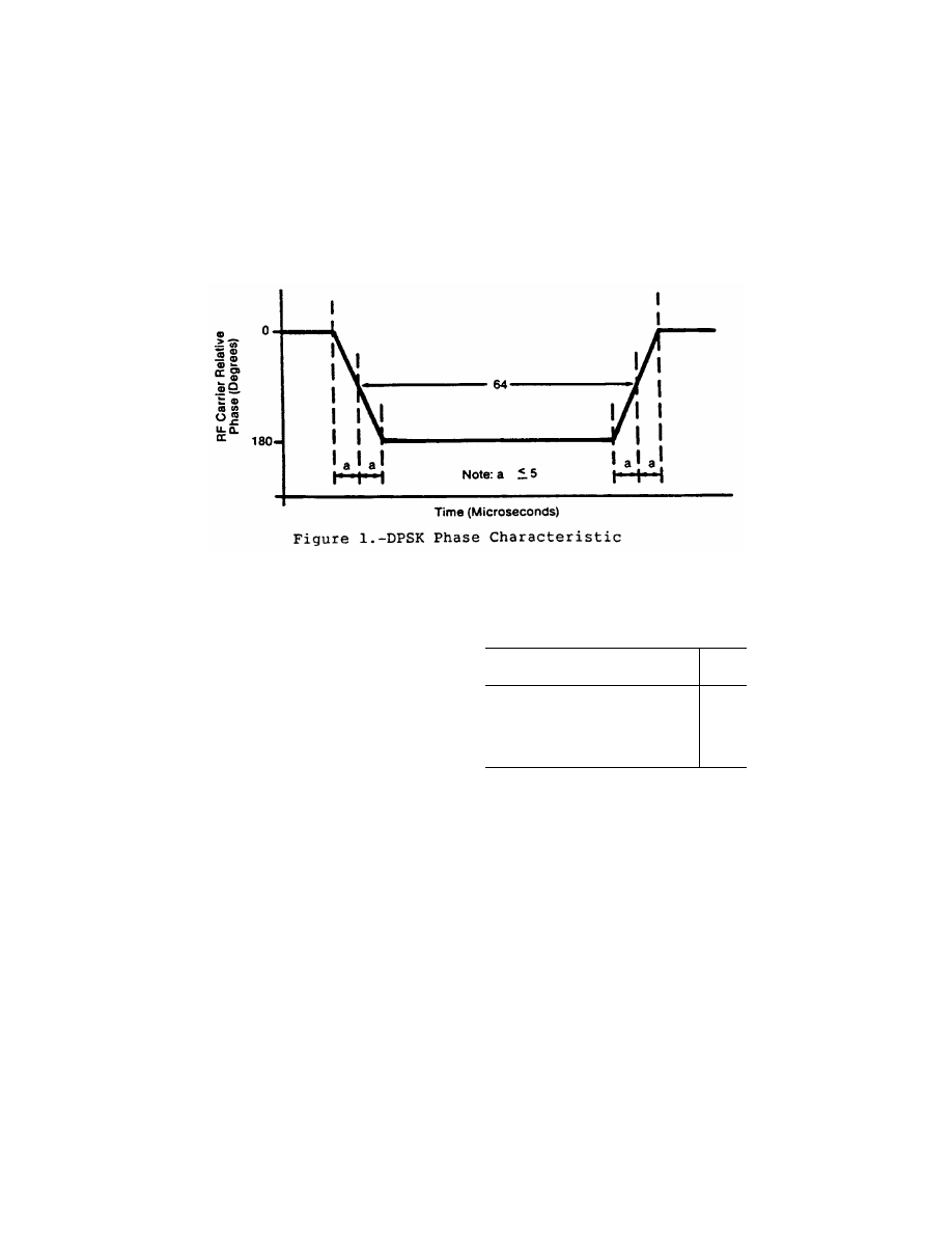
(1) DPSK. The DPSK signal must
have the following characteristics:
bit rate ..............................
15.625 KHz
bit length ...........................
64 microseconds
logic ‘‘0’’ ............................
no phase transition
logic ‘‘1’’ ............................
phase transition
phase transition ................
less than 10 microseconds
phase tolerance ................
±
10 degrees
The phase shall advance (or retard)
monotonically throughout the transi-
tion region. Amplitude modulation
during the phase transition period
shall not be used.
861
Federal Aviation Administration, DOT
§ 171.311
(2) CW. The CW pulse transmissions
and the CW angle transmissions as may
be required in the signal format of any
function must have characteristics
such that the requirements of para-
graph (d) of this section are met.
(d)
Radio frequency signal spectrum.
The transmitted signal must be such
that during the transmission time, the
mean power density above a height of
600 meters (2000 feet) does not exceed
¥
100.5 dBW/m
2
for angle guidance and
¥
95.5 dBW/m
2
for data, as measured in
a 150 KHz bandwidth centered at a fre-
quency of 840 KHz or more from the as-
signed frequency.
(e)
Synchronization.
Synchronization
between the azimuth and elevation
components is required and, in split-
site configurations, would normally be
accomplished by landline interconnec-
tions. Synchronization monitoring
must be provided to preclude function
overlap.
(f)
Transmission rates.
Angle guidance
and data signals must be transmitted
at the following average repetition
rates:
Function
Average
data rate
(Hertz)
Approach Azimuth .................................................
13
±
0.5
High Rate Approach Azimuth ................................
1
39
±
1.5
Approach Elevation ...............................................
39
±
1.5
Back Azimuth .........................................................
6.5
±
0.25
Basic Data .............................................................
(
2
)
Auxiliary Data ........................................................
(
3
)
1
The higher rate is recommended for azimuth scanning an-
tennas with beamwidths greater than two degrees. It should
be noted that the time available in the signal format for addi-
tional functions is limited when the higher rate is used.
2
Refer to Table 8a.
3
Refer to Table 8c.
(g)
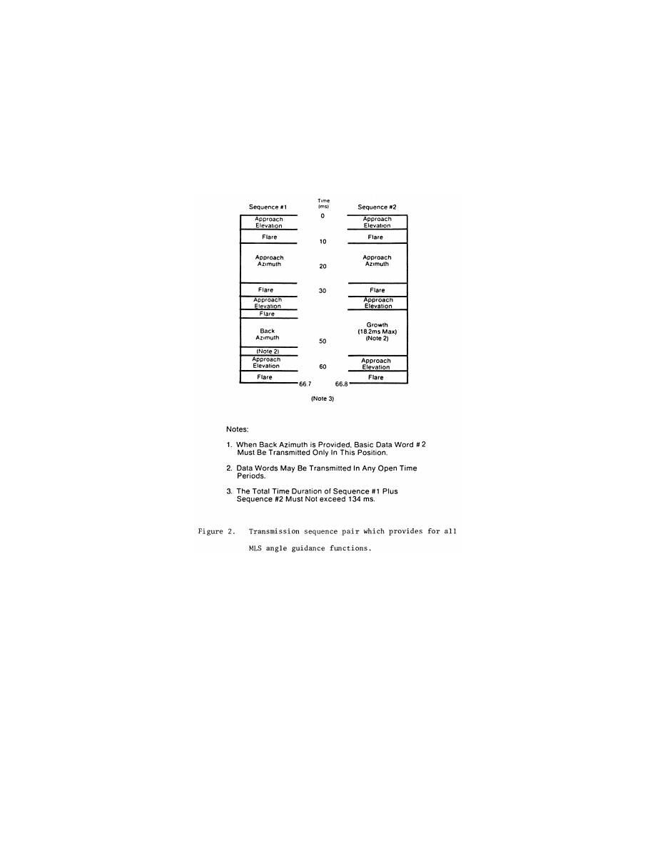
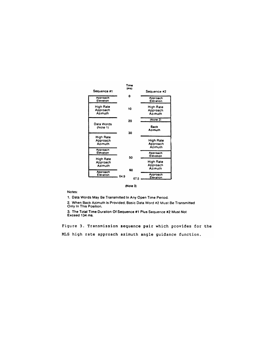
Transmission sequences.
Sequences
of angle transmissions which will gen-
erate the required repetition rates are
shown in Figures 2 and 3.
862
14 CFR Ch. I (1–1–24 Edition)
§ 171.311
863
Federal Aviation Administration, DOT
§ 171.311
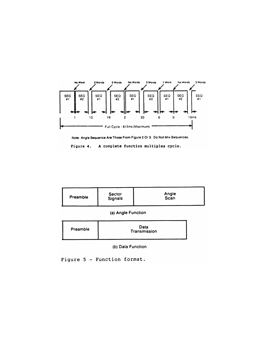
(h)
TDM cycle.
The time periods be-
tween angle transmission sequences
must be varied so that exact repeti-
tions do not occur within periods of
less than 0.5 second in order to protect
against synchronous interference. One
such combination of sequences is
shown in Figure 4 which forms a full
multiplex cycle. Data may be trans-
mitted during suitable open times
within or between the sequences.
864
14 CFR Ch. I (1–1–24 Edition)
§ 171.311
(i)
Function Formats (General).
Each
angle function must contain the fol-
lowing elements: a preamble; sector
signals; and a TO and FRO angle scan
organized as shown in Figure 5a. Each
data function must contain a preamble
and a data transmission period orga-
nized as shown in Figure 5b.
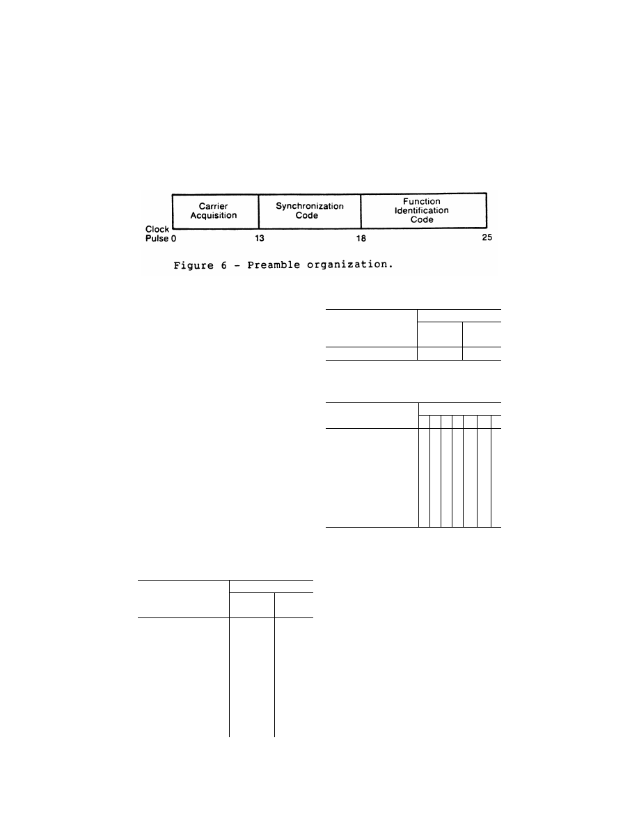
(1)
Preamble format.
The transmitted
angle and date functions must use the
preamble format shown in Figure 6.
This format consists of a carrier acqui-
sition period of unmodulated CW trans-
mission followed by a receiver synchro-
nization code and a function identifica-
tion code. The preamble timing must
be in accordance with Table 2.
865
Federal Aviation Administration, DOT
§ 171.311
(i)
Digital codes.
The coding used in
the preamble for receiver synchroni-
zation is a Barker code logic 11101. The
time of the last phase transition mid-
point in the code shall be the receiver
reference time (see Table 2). The func-
tion identification codes must be as
shown in Table 3. The last two bits (I
11
and I
12
) of the code are parity bits
obeying the equations:
I
6
+ I
7
+ I
8
+ I
9
+ I
10
+ I
11
= Even
I
6
+ I
8
+ I
10
+ I
12
= Even
(ii)
Data modulation.
The digital code
portions of the preamble must be
DPSK modulated in accordance with
§ 171.311(c)(1) and must be transmitted
throughout the function coverage vol-
ume.
(2)
Angle function formats.
The timing
of the angle transmissions must be in
accordance with Tables 4a, 4b, and 5.
The actual timing of the TO and FRO
scans must be as required to meet the
accuracy requirements of §§ 171.313 and
171.317.
(i) Preamble. Must be in accordance
with requirements of § 171.311(i)(1).
T
ABLE
2—P
REAMBLE
T
IMING
1
Event
Event time slot begins at—
15.625 kHz
clock pulse
(number)
Time (milli-
seconds)
Carrier acquisition:
(CW transmission) ...............
0
0
Receiver reference time code:
I
1
= 1 ....................................
13
0 .832
I
2
= 1 ....................................
14
0 .896
I
3
= 1 ....................................
15
0 .960
I
4
= 0 ....................................
16
1 .024
I
5
= 1 ....................................
17
2
1 .088
Function identification:
I
6
...........................................
18
1 .152
I
7
...........................................
19
1 .216
I
8
...........................................
20
1 .280
I
9
...........................................
21
1 .344
I
10
(see table 1) ....................
22
1 .408
I
11
.........................................
23
1 .472
I
12
.........................................
24
1 .536
T
ABLE
2—P
REAMBLE
T
IMING
1
—Continued
Event
Event time slot begins at—
15.625 kHz
clock pulse
(number)
Time (milli-
seconds)
END PREAMBLE .................
25
1 .600
1
Applies to all functions transmitted.
2
Reference time for receiver synchronization for all function
timing.
T
ABLE
3—F
UNCTION
I
DENTIFICATION
C
ODES
Function
Code
I
6
I
7
I
8
I
9
I
10
I
11
I
12
Approach azimuth ....................
0
0
1
1
0
0
1
High rate approach azimuth .....
0
0
1
0
1
0
0
Approach elevation ..................
1
1
0
0
0
0
1
Back azimuth ............................
1
0
0
1
0
0
1
Basic data 1 .............................
0
1
0
1
0
0
0
Basic data 2 .............................
0
1
1
1
1
0
0
Basic data 3 .............................
1
0
1
0
0
0
0
Basic data 4 .............................
1
0
0
0
1
0
0
Basic data 5 .............................
1
1
0
1
1
0
0
Dasic data 6 .............................
0
0
0
1
1
0
1
Auxiliary data A ........................
1
1
1
0
0
1
0
Auxiliary data B ........................
1
0
1
0
1
1
1
Auxiliary data C ........................
1
1
1
1
0
0
0
(ii)
Sector signals.
In all azimuth for-
mats, sector signals must be trans-
mitted to provide Morse Code identi-
fication, airborne antenna selection,
and system test signals. These signals
are not required in the elevation for-
mats. In addition, if the signal from an
installed ground component results in
a valid indication in an area where no
valid guidance should exist, OCI signals
must be radiated as provided for in the
signal format (see Tables 4a, 4b, and 5).
The sector signals are defined as fol-
lows:
(A)
Morse Code.
DPSK transmissions
that will permit Morse Code facility
identification in the aircraft by a four
letter code starting with the letter
‘‘M’’ must be included in all azimuth
functions. They must be transmitted
and repeated at approximately equal
intervals, not less than six times per
866
14 CFR Ch. I (1–1–24 Edition)
§ 171.311
minute, during which time the ground
subsystem is available for operational
use. When the transmissions of the
ground subsystem are not available,
the identification signal must be sup-
pressed. The audible tone in the air-
craft is started by setting the Morse
Code bit to logic ‘‘1’’ and stopped by a
logic ‘‘0’’ (see Tables 4a and 4b). The
identification code characteristics
must conform to the following: the dot
must be between 0.13 and 0.16 second in
duration, and the dash between 0.39 and
0.48 second. The duration between dots
and/or dashes must be one dot plus or
minus 10%. The duration between char-
acters (letters) must not be less than
three dots. When back azimuth is pro-
vided, the code shall be transmitted by
the approach azimuth and back azi-
muth within plus or minus 0.08 seconds.
(B)
Airborne antenna selection.
A sig-
nal for airborne antenna selection shall
be transmitted as a ‘‘zero’’ DPSK sig-
nal lasting for a six-bit period (see Ta-
bles 4a and 4b).
T
ABLE
4a—A
PPROACH
A
ZIMUTH
F
UNCTION
TIMING
Event
Event time slot
begins at—
15.625
kHz clock
pulse
(number)
Time
(milli-
sec-
onds)
Preamble ...............................................
0
0
Morse code ............................................
25
1 .600
Antenna select .......................................
26
1 .664
Rear OCI ...............................................
32
2 .048
Left OCI .................................................
34
2 .176
Right OCI ...............................................
36
2 .304
To test ...................................................
38
2 .432
To scan
1
................................................
40
2 .560
Pause ....................................................
................
8 .760
Midscan point ........................................
................
9 .060
FRO scan
1
............................................
................
9 .360
FRO test ................................................
................
15 .560
End Function (Airborne) ........................
................
15 .688
End guard time; end function (ground)
................
15 .900
AA
1
The actual commencement and completion of the TO
and the FRO scan transmissions are dependent on the
amount of proportional guidance provided. The time slots pro-
vided shall accommodate a maximum scan of plus or minus
62.0 degrees. Scan timing shall be compatible with accuracy
requirements.
T
ABLE
4b—H
IGH
R
ATE
A
PPROACH
A
ZIMUTH AND
B
ACK
A
ZIMUTH
F
UNCTION
T
IMING
Event
Event time slot
begins at—
15.625
kHz clock
pulse
(number)
Time
(milli-
sec-
onds)
Preamble ...............................................
0
0
Morse Code ...........................................
25
1 .600
Antenna select .......................................
26
1 .664
Rear OCI ...............................................
32
2 .048
Left OCI .................................................
34
2 .176
Right OCI ...............................................
36
2 .304
To test ...................................................
38
2 .432
To scan
1
................................................
40
2 .560
Pause ....................................................
................
6 .760
Midscan point ........................................
................
7 .060
FRO scan
1
............................................
................
7 .360
FRO test pulse ......................................
................
11 .560
End function (airborne) ..........................
................
11 .688
End guard time; end function (ground)
................
11 .900
1
The actual commencement and completion of the TO and
the FRO scan transmissions are dependent on the amount of
proportional guidance provided. The time slots provided will
accommodate a maximum scan of plus or minus 42.0 de-
grees. Scan timing shall be compatible with accuracy
requirements.
(C)
OCI.
Where OCI pulses are used,
they must be: (1) greater than any
guidance signal in the OCI sector; (2) at
least 5 dB less than the level of the
scanning beam within the proportional
guidance sector; and (3) for azimuth
functions with clearance signals, at
least 5 dB less than the level of the left
(right) clearance pulses within the left
(right) clearance sector.
T
ABLE
5—A
PPROACH
E
LEVATION
F
UNCTION
T
IMING
Event
Event time slot
begins at:
15.625
kHz clock
pluse
(number)
Time
(milli-
sec-
onds)
Preamble ...............................................
0
0
Processor pause ....................................
25
1 .600
OCI ........................................................
27
1 .728
To scan
1
................................................
29
1 .856
Pause ....................................................
................
3 .406
Midscan point ........................................
................
3 .606
FRO scan
1
............................................
................
3 .806
End function (airborne) ..........................
................
5 .356
End guard time; end function (ground)
................
5 .600
1
The actual commencement and completion of the TO and
FRO scan transmissions are dependent upon the amount of
proportional guidance provided. The time slots provided will
accommodate a maximum scan of
¥
1.5 degrees to + 29.5
degrees. Scan timing shall be compatible with accuracy
requirements.
The duration of each pulse measured
at the half amplitude point shall be at
least 100 microseconds, and the rise and

867
Federal Aviation Administration, DOT
§ 171.311
fall times shall be less then 10 micro-
seconds. It shall be permissible to se-
quentially transmit two pulses in each
out-of-coverage indication time slot.
Where pulse pairs are used, the dura-
tion of each pulse shall be at least 50
microseconds, and the rise and fall
times shall be less then 10 microsec-
onds. The transmission of out-of-cov-
erage indication pulses radiated from
antennas with overlapping coverage
patterns shall be separated by at least
10 microseconds.
N
OTE
: If desired, two pulses may be sequen-
tially transmitted in each OCI time slot.
Where pulse pairs are used, the duration of
each pulse must be 45 (
±
5) microseconds and
the rise and fall times must be less than 10
microseconds.
(D)
System test.
Time slots are pro-
vided in Tables 4a and 4b to allow radi-
ation of TO and FRO test pulses. How-
ever, radiation of these pulses is not re-
quired since the characteristics of
these pulses have not yet been stand-
ardized.
(iii)
Angle encoding.
The encoding
must be as follows:
(A)
General.
Azimuth and elevation
angles are encoded by scanning a nar-
row beam between the limits of the
proportional coverage sector first in
one direction (the TO scan) and then in
the opposite direction (the FRO scan).
Angular information must be encoded
by the amount of time separation be-
tween the beam centers of the TO and
FRO scanning beam pulses. The TO and
FRO transmissions must be symmetri-
cally disposed about the midscan point
listed in Tables 4a, 4b, 5, and 7. The
midscan point and the center of the
time interval between the TO and FRO
scan transmissions must coincide with
a tolerance of
±
10 microseconds. Angu-
lar coding must be linear with angle
and properly decoded using the for-
mula:
θ
=
V
2
T
t
0
−
(
)
where:
q
= Receiver angle in degrees.
V = Scan velocity in degrees per micro-
second.
T
0
= Time separation in microseconds be-
tween TO and FRO beam centers cor-
responding to zero degrees.
t = Time separation in microseconds between
TO and FRO beam centers.
The timing requirements are listed in
Table 6 and illustrated in Figure 7.
868
14 CFR Ch. I (1–1–24 Edition)
§ 171.311
(B)
Azimuth angle encoding.
Each
guidance angle transmitted must con-
sist of a clockwise TO scan followed by
a counterclockwise FRO scan as viewed
from above the antenna. For approach
azimuth functions, increasing angle
values must be in the direction of the
TO scan; for the back azimuth func-
tion, increasing angle values must be
in the direction of the FRO scan. The
antenna has a narrow beam in the
plane of the scan direction and a broad
beam in the orthogonal plane which
fills the vertical coverage.
(C)
Elevation angle encoding.
The radi-
ation from elevation equipment must
produce a beam which scans from the
horizon up to the highest elevation
angle and then scans back down to the
horizon. The antenna has a narrow
beam in the plane of the scan direction
and a broad beam in the orthogonal
plane which fills the horizontal cov-
erage. Elevation angles are defined
from the horizontal plane containing
the antenna phase center; positive an-
gles are above the horizontal and zero
angle is along the horizontal.
(iv)
Clearance guidance.
The timing of
the clearance pulses must be in accord-
ance with Figure 8. For azimuth ele-
ments with proportional coverage of
less than
±
40 degrees (
±
20 degrees for
back azimuth), clearance guidance in-
formation must be provided by trans-
mitting pulses in a TO and FRO format
adjacent to the stop/start times of the
scanning beam signal. The fly-right
clearance pulses must represent posi-
tive angles and the fly-left clearance
pulses must represent negative angles.
The duration of each clearance pulse
must be 50 microseconds with a toler-
ance of
±
5 microseconds. The trans-
mitter switching time between the
clearance pulses and the scanning

869
Federal Aviation Administration, DOT
§ 171.311
beam transmissions must not exceed 10
microseconds. The rise time at the
edge of each clearance pulse must be
less than 10 microseconds. Within the
fly-right clearance guidance section,
the fly-right clearance guidance signal
shall exceed scanning beam antenna
sidelobes and other guidance and OCI
signals by at least 5 dB; within the fly-
left clearance guidance sector, the fly
left clearance guidance signal shall ex-
ceed scanning beam antenna sidelobes
and all other guidance and OCI signals
by at least 5 dB; within the propor-
tional guidance sector, the clearance
guidance signals shall be at least 5dB
below the proportional guidance signal.
Optionally, clearance guidance may be
provided by scanning throughout the
approach guidance sector. For angles
outside the approach azimuth propor-
tional coverage limits as set in Basic
Data Word One (Basic Data Word 5 for
back azimuth), proper decode and dis-
play of clearance guidance must occur
to the limits of the guidance region.
Where used, clearance pulses shall be
transmitted adjacent to the scanning
beam signals at the edges of propor-
tional coverage as shown in Figure 8.
The proportional coverage boundary
shall be established at one beamwidth
inside the scan start/stop angles, such
that the transition between scanning
beam and clearance signals occurs out-
side the proportional coverage sector.
When clearance pulses are provided in
conjunction with a narrow beamwidth
(e.g., one degree) scanning antenna, the
scanning beam antenna shall radiate
for 15 microseconds while stationary at
the scan start/stop angles.
(3)
Data function format.
Basic data
words provide equipment characteris-
tics and certain siting information.
Basic data words must be transmitted
from an antenna located at the ap-
proach azimuth or back azimuth site
which provides coverage throughout
the appropriate sector. Data function
timing must be in accordance with
Table 7a.
T
ABLE
6—A
NGLE
S
CAN
T
IMING
C
ONSTANTS
Function
Max
value of
t
(usec)
T
o
(usec)
V(deg/
usec)
T
m
(usec)
Pause
time
(usec)
T
t
(usec)
Approach azimuth .....................................................................
13,000
6,800
0.02
7,972
600
13,128
High rate approach azimuth ......................................................
9,000
4,800
0.02
5,972
600
9,128
Approach elevation ...................................................................
3,500
3,350
0.02
2,518
400
N/A
Back azimuth .............................................................................
9,000
4,800
¥
0.02
5,972
600
9,128
T
ABLE
7a—B
ASIC
D
ATA
F
UNCTION
T
IMING
Event
Event time slot
begins at:
1
15.625
kHz clock
pulse
(number)
Time
(milli-
sec-
onds)
Preamble ...............................................
0
0
Data transmission (bits I
13
–I
30
) ..............
25
1 .600
Parity transmission (bits I
31
–I
32
) ............
43
2 .752
End function (airborne) ..........................
45
2 .880
End guard time: end function (ground)
................
3 .100
1
The previous event time slot ends at this time.
T
ABLE
7b—A
UXILIARY
D
ATA
F
UNCTION
T
IMING
—
(D
IGITAL
)
Event
Event time slot
begins at:
15.625
kHz clock
pulse
(number)
Time
(milli-
sec-
onds)
Preamble ...............................................
0
0
Address transmission (bits I
13
–I
20
) ........
25
1 .600
Data transmission: (bits I
21
–I
69
) .............
33
2 .112
T
ABLE
7b—A
UXILIARY
D
ATA
F
UNCTION
T
IMING
—
(D
IGITAL
)—Continued
Event
Event time slot
begins at:
15.625
kHz clock
pulse
(number)
Time
(milli-
sec-
onds)
Parity transmission (bits I
70
–I
76
) ............
82
5 .248
End function (airborne) ..........................
89
5 .696
End guard time; end function (ground)
................
5 .900
T
ABLE
7c—A
UXILIARY
D
ATA
F
UNCTION
T
IMING
—
(A
LPHANUMERIC
)
Event
Event time slot
begins at:
15.615
kHz clock
pulse
(number)
Time
(milli-
sec-
onds)
Preamble ...............................................
0
0
Address transmission (bits I
13
–I
20
) ........
25
1 .600
Data transmission: (bits I
21
–I
76
..............
33
2 .112
End function (airborne) ..........................
89
5 .696

870
14 CFR Ch. I (1–1–24 Edition)
§ 171.311
T
ABLE
7c—A
UXILIARY
D
ATA
F
UNCTION
T
IMING
—
(A
LPHANUMERIC
)—Continued
Event
Event time slot
begins at:
15.615
kHz clock
pulse
(number)
Time
(milli-
sec-
onds)
End guard time; (end function ground)
................
5 .900
(i)
Preamble.
Must be in accordance
with requirements of § 171.311(i)(1).
(ii)
Data transmissions.
Basic data
must be transmitted using DPSK mod-
ulation. The content and repetition
rate of each basic data word must be in
accordance with Table 8a. For data
containing digital information, binary
number 1 must represent the lower
range limit with increments in binary
steps to the upper range limit shown in
Table 8a. Data containing digital infor-
mation shall be transmitted with the
least significant bit first.
(j)
Basic Data word requirements.
Basic
Data shall consist of the items speci-
fied in Table 8a. Basic Data word con-
tents shall be defined as follows:
(1)
Approach azimuth to threshold dis-
tance
shall represent the minimum dis-
tance between the Approach Azimuth
antenna phase center and the vertical
plane perpendicular to the centerline
which contains the landing threshold.
(2)
Approach azimuth proportional cov-
erage limit
shall represent the limit of
the sector in which proportional ap-
proach azimuth guidance is trans-
mitted.
(3)
Clearance signal type
shall rep-
resent the type of clearance when used.
Pulse clearance is that which is in ac-
cordance with § 171.311 (i) (2) (iv). Scan-
ning Beam (SB) clearance indicates
that the proportional guidance sector
is limited by the proportional coverage
limits set in basic data.
871
Federal Aviation Administration, DOT
§ 171.311
872
14 CFR Ch. I (1–1–24 Edition)
§ 171.311
T
ABLE
8a—B
ASIC
D
ATA
W
ORDS
Data bit
#
Data item definition
LSB
value
Data bit
value
Basic Data Word No. 1
1
Preamble .........................
N/A 1
2
..........................................
............
1
3
..........................................
............
1
4
..........................................
............
0
5
..........................................
............
1
6
..........................................
............
0
7
..........................................
............
1
8
..........................................
............
0
9
..........................................
............
1
10
..........................................
............
0
11
..........................................
............
0
12
..........................................
............
0
13
Approach azimuth to
threshold distance
(Om
¥
630m).
100m 100m
14
..........................................
............
200m
15
..........................................
............
400m
16
..........................................
............
800m
17
..........................................
............
1600m
18
..........................................
............
3200m
19
Approach azimuth propor-
tional coverage limit
(negative limit) (0
°
to
¥
62
°
).
2
°
¥
2
°
20
..........................................
............
¥
4
°
21
..........................................
............
¥
8
°
22
..........................................
............
¥
16
°
23
..........................................
............
¥
32
°
24
Approach azimuth propor-
tional coverage limit
(positive limit) (0
°
to +
62
°
).
2
°
2
°
25
..........................................
............
4
°
26
..........................................
............
8
°
27
..........................................
............
16
°
28
..........................................
............
32
°
29
Clearance signal type ......
N/A 0 = pulse; 1
= SB
30
Spare ...............................
............
Transmit
zero
31
Parity: (13 + 14 + 15. . .
+ 30 + 31 = odd).
N/A N/A
32
Parity: (14 + 16 + 18. . .
+ 30 + 32 = odd).
N/A N/A
Note 1: Transmit throughout the Approach Azimuth guidance
sector at intervals of 1.0 seconds or less.
Note 2: The all zero state of the data field represents the
lower limit of the absolute value of the coded parameter
unless otherwise noted.
Basic Data Word No. 2
1
Preamble .........................
N/A 1
2
..........................................
............
1
3
..........................................
............
1
4
..........................................
............
0
5
..........................................
............
1
6
..........................................
............
0
7
..........................................
............
1
8
..........................................
............
1
9
..........................................
............
1
10
..........................................
............
1
11
..........................................
............
0
12
..........................................
............
0
13
Minimum glide path (2.0
°
to 14.7
°
).
0.1
°
0.1
°
14
..........................................
............
0.2
°
15
..........................................
............
0.4
°
16
..........................................
............
0.8
°
T
ABLE
8a—B
ASIC
D
ATA
W
ORDS
—Continued
Data bit
#
Data item definition
LSB
value
Data bit
value
17
..........................................
............
1.6
°
18
..........................................
............
3.2
°
19
..........................................
............
6.4
°
20
Back azimuth status ........
............
see note 4
21
DME status ......................
............
see note 6
22
..........................................
............
23
Approach azimuth status
............
see note 4
24
Approach azimuth status
............
see note 4
25
Spare ...............................
............
Transmit
zero
26
......do ...............................
............
Do.
27
......do ...............................
............
Do.
28
......do ...............................
............
Do.
29
......do ...............................
............
Do.
30
......do ...............................
............
Do.
31
Parity: (13 + 14 + 15. . .
+ 30 + 31) = odd).
N/A N/A
32
Parity: (14 + 16 + 18. . .
+ 30 + 32 = odd).
N/A N/A
Note 1: Transmit throughout the Approach Azimuth guidance
sector at intervals of 0.16 seconds or less.
Note 2: The all zero state of the data field represents the
lower limit of the absolute range of the coded parameter
unless otherwise noted.
Basic Data Word No. 3
1
Preamble .........................
N/A 1
2
..........................................
............
1
3
..........................................
............
1
4
..........................................
............
0
5
..........................................
............
1
6
..........................................
............
1
7
..........................................
............
0
8
..........................................
............
1
9
..........................................
............
0
10
..........................................
............
0
11
..........................................
............
0
12
..........................................
............
0
13
Approach azimuth beam-
width (0.5
°
¥
4.0
°
) See
note 7.
0.5
°
0.5
°
14
..........................................
............
1.0
°
15
..........................................
............
2.0
°
16
Approach elevation
beamwidth (0.5
°
to
2.5
°
) See note 7.
0.5
°
0.5
°
17
..........................................
............
1.0
°
18
Note: values greater than
2.5
°
are invalid.
............
2.0
°
19
DME distance (Om to
6387.5m.
12.5m 12.5m
20
..........................................
............
25.0m
21
..........................................
............
50.0m
22
..........................................
............
100.0m
23
..........................................
............
200.0m
24
..........................................
............
400.0m
25
..........................................
............
800.0m
26
..........................................
............
1600.0m
27
..........................................
............
3200.0m
28
Spare ...............................
............
Transmit
zero
29
......do ...............................
............
Do.
30
......do ...............................
............
Do.
31
Parity: (13 + 14 + 15. . .
+ 30 + 31 = odd).
............
32
Parity: (14 + 16 + 18. . .
+ 30 + 32 = odd).
N/A N/A

873
Federal Aviation Administration, DOT
§ 171.311
T
ABLE
8a—B
ASIC
D
ATA
W
ORDS
—Continued
Data bit
#
Data item definition
LSB
value
Data bit
value
Note 1: Transmit throughout the Approach Azimuth guidance
sector at intervals of 1.0 seconds or less.
Note 2: The all zero state of the data field represents the
lower limit of the absolute range of the coded parameter
unless otherwise noted.
Basic Data Word No. 4
1
Preamble .........................
N/A 1
2
..........................................
............
1
3
..........................................
............
1
4
..........................................
............
0
5
..........................................
............
1
6
..........................................
............
1
7
..........................................
............
0
8
..........................................
............
0
9
..........................................
............
0
10
..........................................
............
1
11
..........................................
............
0
12
..........................................
............
0
13
Approach azimuth mag-
netic orientation (0
°
to
359
°
).
1
°
1
°
14
..........................................
............
2
°
15
..........................................
............
4
°
16
..........................................
............
8
°
17
..........................................
............
16
°
18
..........................................
............
32
°
19
..........................................
............
64
°
20
..........................................
............
128
°
21
..........................................
............
256
°
22
Back azimuth magnetic
orientation (0
°
to 359
°
).
1
°
1
°
23
..........................................
............
2
°
24
..........................................
............
4
°
25
..........................................
............
8
°
26
..........................................
............
16
°
27
..........................................
............
32
°
28
..........................................
............
64
°
29
..........................................
............
128
°
30
..........................................
............
256
°
31
Parity: (13 + 14 + 15. . .
+ 30 + 31 = odd).
N/A N/A
32
Parity: (14 + 16 + 18. . .
+ 30 + 32 = odd).
N/A N/A
Note 1: Transmit at intervals of 1.0 second or less through-
out the Approach Azimuth guidance sector, except when
Back Azimuth guidance is provided. See Note 8.
Note 2: The all zero state of the data field represents the
lower limit of the absolute range of the coded parameter
unless otherwise noted.
Basic Data Word No. 5
1
Preamble .........................
N/A 1
2
..........................................
............
1
3
..........................................
............
1
4
..........................................
............
0
5
..........................................
............
1
6
..........................................
............
1
7
..........................................
............
1
8
..........................................
............
0
9
..........................................
............
1
10
..........................................
............
1
11
..........................................
............
0
12
..........................................
............
0
13
Back azimuth proportional
coverage negative limit
(0
°
to
¥
42
°
).
2
°
¥
2
°
14
..........................................
............
¥
4
°
15
..........................................
............
¥
8
°
T
ABLE
8a—B
ASIC
D
ATA
W
ORDS
—Continued
Data bit
#
Data item definition
LSB
value
Data bit
value
16
..........................................
............
¥
16
°
17
..........................................
............
¥
32
°
18
Back azimuth proportional
coverage positive limit
(0
°
to + 42
°
).
2
°
2
°
19
..........................................
............
4
°
20
..........................................
............
8
°
21
..........................................
............
16
°
22
..........................................
............
32
°
23
Back azimuth beamwidth
(0.5
°
to 4.0
°
) See note
7.
0.5
°
0.5
°
24
..........................................
............
1.0
°
25
..........................................
............
2.0
°
26
Back azimuth status ........
............
See Note 10
27
......do ...............................
............
Do.
28
......do ...............................
............
Do.
29
......do ...............................
............
Do.
30
......do ...............................
............
Do.
31
Parity: (13 + 14 + 15. . .
+ 30 + 31 = odd).
N/A N/A
32
Parity: (14 + 16 + 18. . .
+ 30 + 32 = odd).
N/A N/A
Note 1: Transmit only when Back Azimuth guidance is pro-
vided. See note 9.
Note 2: The all zero state of the data filed represents the
lower limit of the absolute range of the coded parameter
unless otherwise noted.
Basic Data Word No. 6
1
Preamble .........................
N/A 1
2
..........................................
............
1
3
..........................................
............
1
4
..........................................
............
0
5
..........................................
............
1
6
..........................................
............
0
7
..........................................
............
0
8
..........................................
............
0
9
..........................................
............
1
10
..........................................
............
1
11
..........................................
............
0
12
..........................................
............
1
(13–
30)
MLS ground equipment
identification (Note 3).
............
13
Character 2 ......................
N/A B1
14
..........................................
............
B2
15
..........................................
............
B3
16
..........................................
............
B4
17
..........................................
............
B5
18
..........................................
............
B6
19
Character 3 ......................
N/A B1
20
..........................................
............
B2
21
..........................................
............
B3
22
..........................................
............
B4
23
..........................................
............
B5
24
..........................................
............
B6
25
Character 4 ......................
N/A B1
26
..........................................
............
B2
27
..........................................
............
B3
28
..........................................
............
B4
29
..........................................
............
B5
30
..........................................
............
B6
31
Parity: (13 + 14 + 15. . .
+ 30 + 31 = odd).
N/A N/A
32
Parity: (14 + 16 + 18. . .
+ 30 + 32 = odd).
N/A N/A
Note 1: Transmit at intervals of 1.0 second or less through-
out the Approach Azimuth guidance sector, except when Back
Azimuth guidance is provided. See note 8.

874
14 CFR Ch. I (1–1–24 Edition)
§ 171.311
Note 3: Characters are encoded using the International Al-
phabet Number 5, (IA–5):
Note 4: Coding for status bit:
0 = Function not radiated, or radiated in test mode (not reli-
able for navigation).
1 = Function radiated in normal mode (for Back Azimuth,
this also indicates that a Back Azimuth transmission follows).
Note 5: Date items which are not applicable to a particular
ground equipment shall be transmitted as all zeros.
Note 6: Coding for status bits:
I
21
I
22
0
0 DME transponder inoperative or not available.
1
0 Only IA mode or DME/N available.
0
0 FA mode, Standard 1, available.
1
1 FA mode, Standard 2, available.
Note 7: The value coded shall be the actual beamwidth (as
defined in § 171.311 (j)(9) rounded to the nearest 0.5 degree.
Note 8: When back Azimuth guidance is provided, Data
Words 4 and 6 shall be transmitted at intervals of 1.33 sec-
onds or less throughout the Approach Azimuth coverage and
4 seconds or less throughout the Back Azimuth coverage.
Note 9: When Back Azimuth guidance is provided, Data
Word 5 shall be transmitted at an interval of 1.33 seconds or
less throughout the Back Azimuth coverage sector and 4 sec-
onds or less throughout the Approach Azimuth coverage sec-
tor.
Note 10: Coding for status bit:
0 = Function not radiated, or radiated in test mode (not reli-
able for navigation).
1 = Function radiated in normal mode.
(4)
Minimum glidepath
the lowest
angle of descent along the zero degree
azimuth that is consistent with pub-
lished approach procedures and obsta-
cle clearance criteria.
(5)
Back azimuth status
shall represent
the operational status of the Back Azi-
muth equipment.
(6)
DME status
shall represent the
operational status of the DME equip-
ment.
(7)
Approach azimuth status
shall rep-
resent the operational status of the ap-
proach azimuth equipment.
(8)
Approach elevation status
shall rep-
resent the operational status of the ap-
proach elevation equipment.
(9)
Beamwidth
the width of the scan-
ning beam main lobe measured at the
¥
3 dB points and defined in angular
units on the antenna boresight, in the
horizontal plane for the azimuth func-
tion and in the vertical plane for the
elevation function.
(10)
DME distance
shall represent the
minimum distance between the DME
antenna phase center and the vertical
plane perpendicular to the runway cen-
terline which contains the MLS datum
point.
(11)
Approach azimuth magnetic ori-
entation
shall represent the angle meas-
ured in the horizontal plane clockwise
from Magnetic North to the zero-de-
gree angle guidance radial originating
from the approach azimuth antenna
phase center. The vertex of the meas-
ured angle shall be at the approach azi-
muth antenna phase center.
N
OTE
: For example, this data item would
be encoded 090 for an approach azimuth an-
tenna serving runway 27 (assuming the mag-
netic heading is 270 degrees) when sited such
that the zero degree radial is parallel to cen-
terline.
(12)
Back azimuth magnetic orientation
shall represent the angle measured in
the horizontal plane clockwise from
Magnetic North to the zero-degree
angle guidance radial originating from
the Back Azimuth antenna. The vertex
of the measured angle shall be at the
Back Azimuth antenna phase center.
N
OTE
: For example, this data item would
be encoded 270 for a Back Azimuth Antenna
serving runway 27 (assuming the magnetic
heading is 270 degrees) when sited such that
the zero degree radial is parallel to center-
line.
(13)
Back azimuth proportional cov-
erage limit
shall represent the limit of
the sector in which proportional back
azimuth guidance is transmitted.
(14)
MLS ground equipment identifica-
tion
shall represent the last three char-
acters of the system identification
specified in § 171.311(i)(2). The char-
acters shall be encoded in accordance
with International Alphabet No. 5 (IA–
5) using bits b
1
through b
6
.
N
OTE
: Bit b
7
of this code may be recon-
structed in the airborne receiver by taking
the complement of bit b
6
.
(k)
Residual radiation.
The residual
radiation of a transmitter associated
with an MLS function during time in-
tervals when it should not be transmit-
ting shall not adversely affect the re-
ception of any other function. The re-
sidual radiation of an MLS function at
times when another function is radi-
ating shall be at least 70 dB below the
level provided when transmitting.
(l)
Symmetrical scanning.
The TO and
FRO scan transmissions shall be sym-
metrically disposed about the mid-scan
point listed in Tables 4a, 4b and 5. The
mid-scan point and the center of the
time interval between the TO and FRO
scan shall coincide with a tolerance of
plus or minus 10 microseconds.
(m)
Auxiliary data
—(1)
Addresses.
Three function identification codes are
reserved to indicate transmission of
Auxiliary Data A, Auxiliary Data B,

875
Federal Aviation Administration, DOT
§ 171.313
and Auxiliary Data C. Auxiliary Data
A contents are specified below, Auxil-
iary Data B contents are reserved for
future use, and Auxiliary Data C con-
tents are reserved for national use. The
address codes of the auxiliary data
words shall be as shown in Table 8b.
(2)
Organization and timing.
The orga-
nization and timing of digital auxiliary
data must be as specified in Table 7b.
Data containing digital information
must be transmitted with the least sig-
nificant bit first. Alphanumeric data
characters must be encoded in accord-
ance with the 7-unit code character set
as defined by the American National
Standard Code for Information Inter-
change (ASCII). An even parity bit is
added to each character. Alphanumeric
data must be transmitted in the order
in which they are to be read. The serial
transmission of a character must be
with the lower order bit transmitted
first and the parity bit transmitted
last. The timing for alphanumeric aux-
iliary data must be as shown in Table
7c.
(3)
Auxiliary Data A content:
The data
items specified in Table 8c are defined
as follows:
(i)
Approach azimuth antenna offset
shall represent the minimum distance
between the Approach Azimuth an-
tenna phase center and the vertical
plane containing the runway center-
line.
(ii)
Approach azimuth to MLS datum
point distance
shall represent the min-
imum distance between the Approach
Azimuth antenna phase center and the
vertical plane perpendicular to the cen-
terline which contains the MLS datum
point.
(iii)
Approach azimuth alignment with
runway centerline
shall represent the
minimum angle between the approach
azimuth antenna zero-degree guidance
plane and the runway certerline.
(iv)
Approach azimuth antenna coordi-
nate system
shall represent the coordi-
nate system (planar or conical) of the
angle data transmitted by the ap-
proach azimuth antenna.
(v)
Approach elevation antenna offset
shall represent the minimum distance
between the elevation antenna phase
center and the vertical plane con-
taining the runway centerline.
(vi)
MLS datum point to threshold dis-
tance
shall represent the distance
measured along the runway centerline
from the MLS datum point to the run-
way threshold.
(vii)
Approach elevation antenna
height
shall represent the height of the
elevation antenna phase center rel-
ative to the height of the MLS datum
point.
(viii)
DME offset
shall represent the
minimum distance between the DME
antenna phase center and the vertical
plane containing the runway center-
line.
(ix)
DME to MLS datum point distance
shall represent the minimum distance
between the DME antenna phase center
and the vertical plane perpendicular to
the centerline which contains the MLS
datum point.
(x)
Back azimuth antenna offset
shall
represent the minimum distance be-
tween the back azimuth antenna phase
center and the vertical plane con-
taining the runway centerline.
(xi)
Back azimuth to MLS datum point
distance
shall represent the minimum
distance between the Back Azimuth
antenna and the vertical plane perpen-
dicular to the centerline which con-
tains the MLS datum point.
(xii)
Back azimuth antenna alignment
with runway centerline
shall represent
the minimum angle between the back
azimuth antenna zero-degree guidance
plane and the runway centerline.
§ 171.313 Azimuth performance re-
quirements.
This section prescribes the perform-
ance requirements for the azimuth
equipment of the MLS as follows:
(a)
Approach azimuth coverage require-
ments.
The approach azimuth equip-
ment must provide guidance informa-
tion in at least the following volume of
space (see Figure 9):
T
ABLE
8b—A
UXILIARY
D
ATA
W
ORD
A
DDRESS
C
ODES
No.
I
13
I
14
I
15
I
16
I
17
I
18
I
19
I
20
1.
0
0
0
0
0
1
1
1
2.
0
0
0
0
1
0
1
0
3.
0
0
0
0
1
1
0
1
4.
0
0
0
1
0
0
1
1
5.
0
0
0
1
0
1
0
0
6.
0
0
0
1
1
0
0
1
7.
0
0
0
1
1
1
1
0
8.
0
0
1
0
0
0
1
0