
875
Federal Aviation Administration, DOT
§ 171.313
and Auxiliary Data C. Auxiliary Data
A contents are specified below, Auxil-
iary Data B contents are reserved for
future use, and Auxiliary Data C con-
tents are reserved for national use. The
address codes of the auxiliary data
words shall be as shown in Table 8b.
(2)
Organization and timing.
The orga-
nization and timing of digital auxiliary
data must be as specified in Table 7b.
Data containing digital information
must be transmitted with the least sig-
nificant bit first. Alphanumeric data
characters must be encoded in accord-
ance with the 7-unit code character set
as defined by the American National
Standard Code for Information Inter-
change (ASCII). An even parity bit is
added to each character. Alphanumeric
data must be transmitted in the order
in which they are to be read. The serial
transmission of a character must be
with the lower order bit transmitted
first and the parity bit transmitted
last. The timing for alphanumeric aux-
iliary data must be as shown in Table
7c.
(3)
Auxiliary Data A content:
The data
items specified in Table 8c are defined
as follows:
(i)
Approach azimuth antenna offset
shall represent the minimum distance
between the Approach Azimuth an-
tenna phase center and the vertical
plane containing the runway center-
line.
(ii)
Approach azimuth to MLS datum
point distance
shall represent the min-
imum distance between the Approach
Azimuth antenna phase center and the
vertical plane perpendicular to the cen-
terline which contains the MLS datum
point.
(iii)
Approach azimuth alignment with
runway centerline
shall represent the
minimum angle between the approach
azimuth antenna zero-degree guidance
plane and the runway certerline.
(iv)
Approach azimuth antenna coordi-
nate system
shall represent the coordi-
nate system (planar or conical) of the
angle data transmitted by the ap-
proach azimuth antenna.
(v)
Approach elevation antenna offset
shall represent the minimum distance
between the elevation antenna phase
center and the vertical plane con-
taining the runway centerline.
(vi)
MLS datum point to threshold dis-
tance
shall represent the distance
measured along the runway centerline
from the MLS datum point to the run-
way threshold.
(vii)
Approach elevation antenna
height
shall represent the height of the
elevation antenna phase center rel-
ative to the height of the MLS datum
point.
(viii)
DME offset
shall represent the
minimum distance between the DME
antenna phase center and the vertical
plane containing the runway center-
line.
(ix)
DME to MLS datum point distance
shall represent the minimum distance
between the DME antenna phase center
and the vertical plane perpendicular to
the centerline which contains the MLS
datum point.
(x)
Back azimuth antenna offset
shall
represent the minimum distance be-
tween the back azimuth antenna phase
center and the vertical plane con-
taining the runway centerline.
(xi)
Back azimuth to MLS datum point
distance
shall represent the minimum
distance between the Back Azimuth
antenna and the vertical plane perpen-
dicular to the centerline which con-
tains the MLS datum point.
(xii)
Back azimuth antenna alignment
with runway centerline
shall represent
the minimum angle between the back
azimuth antenna zero-degree guidance
plane and the runway centerline.
§ 171.313 Azimuth performance re-
quirements.
This section prescribes the perform-
ance requirements for the azimuth
equipment of the MLS as follows:
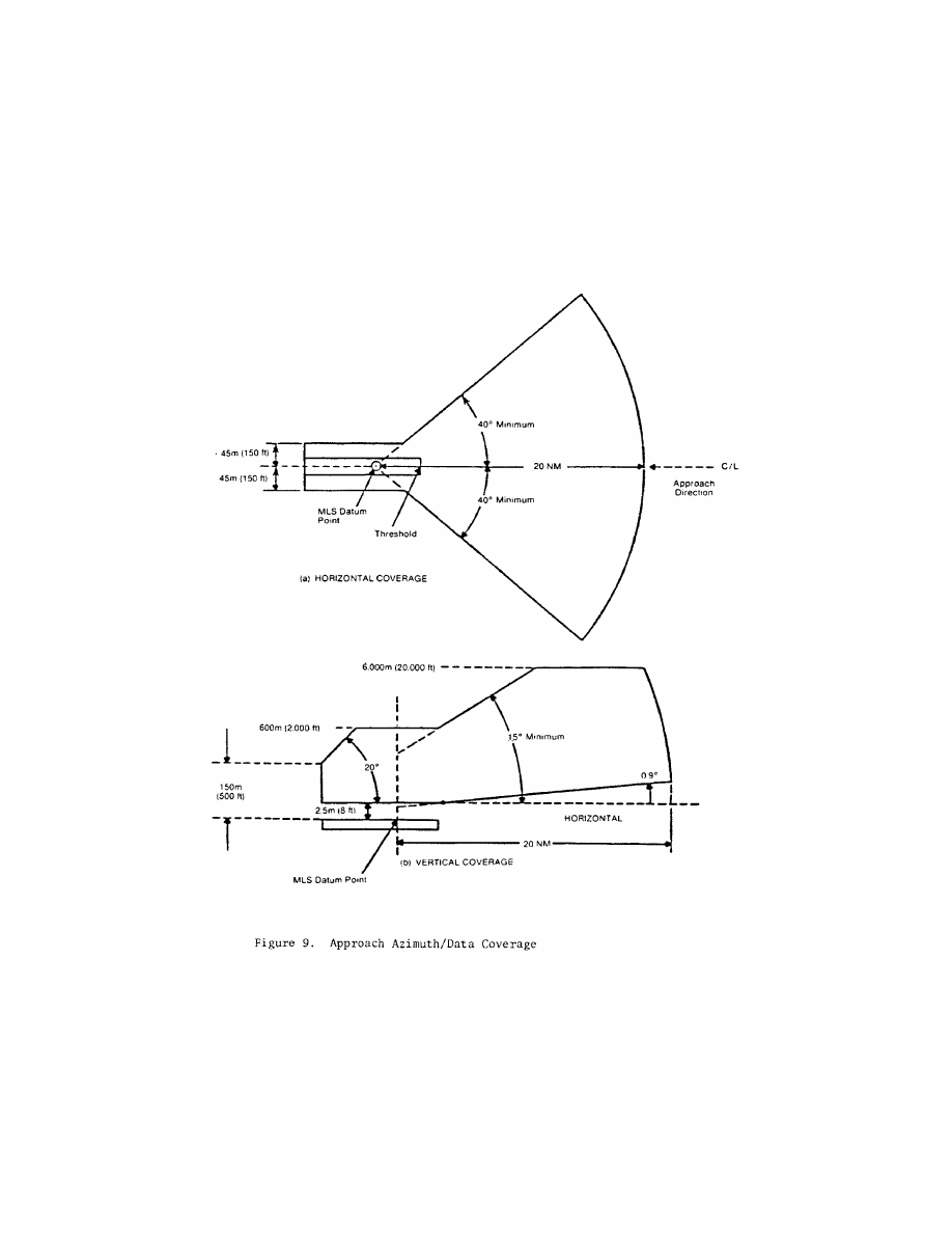
(a)
Approach azimuth coverage require-
ments.
The approach azimuth equip-
ment must provide guidance informa-
tion in at least the following volume of
space (see Figure 9):
T
ABLE
8b—A
UXILIARY
D
ATA
W
ORD
A
DDRESS
C
ODES
No.
I
13
I
14
I
15
I
16
I
17
I
18
I
19
I
20
1.
0
0
0
0
0
1
1
1
2.
0
0
0
0
1
0
1
0
3.
0
0
0
0
1
1
0
1
4.
0
0
0
1
0
0
1
1
5.
0
0
0
1
0
1
0
0
6.
0
0
0
1
1
0
0
1
7.
0
0
0
1
1
1
1
0
8.
0
0
1
0
0
0
1
0
876
14 CFR Ch. I (1–1–24 Edition)
§ 171.313
T
ABLE
8b—A
UXILIARY
D
ATA
W
ORD
A
DDRESS
C
ODES
—Continued
No.
I
13
I
14
I
15
I
16
I
17
I
18
I
19
I
20
9.
0
0
1
0
0
1
0
1
10.
0
0
1
0
1
0
0
0
11.
0
0
1
0
1
1
1
1
12.
0
0
1
1
0
0
0
1
13.
0
0
1
1
0
1
1
0
14.
0
0
1
1
1
0
1
1
15.
0
0
1
1
1
1
0
0
16.
0
1
0
0
0
0
1
1
17.
0
1
0
0
0
1
0
0
18.
0
1
0
0
1
0
0
1
19.
0
1
0
0
1
1
1
0
20.
0
1
0
1
0
0
0
0
21.
0
1
0
1
0
1
1
1
22.
0
1
0
1
1
0
1
0
23.
0
1
0
1
1
1
0
1
24.
0
1
1
0
0
0
0
1
25.
0
1
1
0
0
1
1
0
26.
0
1
1
0
1
0
1
1
27.
0
1
1
0
1
1
0
0
28.
0
1
1
1
0
0
1
0
29.
0
1
1
1
0
1
0
1
30.
0
1
1
1
1
0
0
0
31.
0
1
1
1
1
1
1
1
32.
1
0
0
0
0
0
1
0
33.
1
0
0
0
0
1
0
1
34.
1
0
0
0
1
0
0
0
35.
1
0
0
0
1
1
1
1
36.
1
0
0
1
0
0
0
1
37.
1
0
0
1
0
1
1
0
38.
1
0
0
1
1
0
1
1
39.
1
0
0
1
1
1
0
0
40.
1
0
1
0
0
0
0
0
T
ABLE
8b—A
UXILIARY
D
ATA
W
ORD
A
DDRESS
C
ODES
—Continued
No.
I
13
I
14
I
15
I
16
I
17
I
18
I
19
I
20
41.
1
0
1
0
0
1
1
1
42.
1
0
1
0
1
0
1
0
43.
1
0
1
0
1
1
0
1
44.
1
0
1
1
0
0
1
1
45.
1
0
1
1
0
1
0
0
46.
1
0
1
1
1
0
0
1
47.
1
0
1
1
1
1
1
0
48.
1
1
0
0
0
0
0
1
49.
1
1
0
0
0
1
1
0
50.
1
1
0
0
1
0
1
1
51.
1
1
0
0
1
1
0
0
52.
1
1
0
1
0
0
1
0
53.
1
1
0
1
0
1
0
1
54.
1
1
0
1
1
0
0
0
55.
1
1
0
1
1
1
1
1
56.
1
1
1
0
0
0
1
1
57.
1
1
1
0
0
1
0
0
58.
1
1
1
0
1
0
0
1
59.
1
1
1
0
1
1
1
0
60.
1
1
1
1
0
0
0
0
61.
1
1
1
1
0
1
1
1
62.
1
1
1
1
1
0
1
0
63.
1
1
1
1
1
1
0
1
64.
0
0
0
0
0
0
0
0
N
OTE
1: Parity bits I
19
and I
20
are chosen to
satisfy the equations:
I
13
+ I
14
+ I
15
+ I
16
+ I
17
+ I
18
+ I
19
= EVEN
I
14
+ I
16
+ I
18
+ I
20
= EVEN
T
ABLE
8
C
—A
UXILIARY
D
ATA
Word
(See
note 6)
Data content
Type
of data
Maximun
time be-
tween trans-
missions
(Seconds)
Bits
used
Range of values
Least
sig-
nifi-
cant
bit
A1 ......
Preamble .....................................................
Digital
1.0
12 ......................................................
.........
Address ........................................................
...........
....................
8 ......................................................
.........
Approach azimuth antenna offset ...............
...........
....................
10
¥
511 m to + 511 m (See note 3)
1 m
Approach azimuth to MLS datum point dis-
tance.
...........
....................
13 0 m to 8 191 m ............................
1 m
Approach azimuth antenna alignment with
runway centerline.
...........
....................
12
¥
20.47
°
to 20.47
°
(See note 3) ..
0.01
°
Approach azimuth antenna coordinate sys-
tem.
...........
....................
1 (See note 2) .................................
.........
Spare ...........................................................
...........
....................
13 ......................................................
.........
Parity ............................................................
...........
....................
7 (See note 1) .................................
.........
A2 ......
Preamble .....................................................
Digital
1.0
12 ......................................................
.........
Address ........................................................
...........
....................
8 ......................................................
.........
Approach elevation antenna offset ..............
...........
....................
10
¥
511 m to + 511 m (See note 3)
1 m
MLS datum point to threshold distance ......
...........
....................
10 0 m to 1 023 m ............................
1 m
Approach elevation antenna height .............
...........
....................
7
¥
6.3 m to + 6.3 m (See note 3)
0.1
m
Spare ...........................................................
...........
....................
22 ......................................................
.........
Parity ............................................................
...........
....................
7 (See note 1) .................................
.........
A3 ......
Preamble .....................................................
Digital
(See note 4)
12 ......................................................
.........
Address ........................................................
...........
....................
8 ......................................................
.........
DME offset ...................................................
...........
....................
10
¥
511 m to + 511 m ....................
1 m
DME to MLS datum point distance .............
...........
....................
14
¥
8 191 m to + 8 191 m (See
note 3).
1 m
Spare ...........................................................
...........
....................
25 ......................................................
.........
Parity ............................................................
...........
....................
7 (See note 1) .................................
.........
A4 ......
Preamble .....................................................
Digital
(See note 5)
12 ......................................................
.........
Address ........................................................
...........
....................
8 ......................................................
.........
Back azimuth antenna .................................
...........
....................
10
¥
511 m to + 511 m (See note 3)
1 m
Back azimuth to MLS datum point distance
...........
....................
11 0 m to 2 047 m ............................
1 m

877
Federal Aviation Administration, DOT
§ 171.313
T
ABLE
8
C
—A
UXILIARY
D
ATA
—Continued
Word
(See
note 6)
Data content
Type
of data
Maximun
time be-
tween trans-
missions
(Seconds)
Bits
used
Range of values
Least
sig-
nifi-
cant
bit
Back azimuth antenna alignment with run-
way centerline.
...........
....................
12
¥
20.47
°
to 20.47
°
(See note 3) ..
0.01
°
Spare ...........................................................
...........
....................
16 ......................................................
.........
Parity ............................................................
...........
....................
7 (See note 1) .................................
.........
N
OTE
1: Parity bits I
70
to I
76
are chosen to
satisfy the equations which follow:
For BIT I
70
:
Even = (I
13
+ ... + I
18
) + I
20
+ I
22
+ I
24
+ I
25
+ I
28
+ I
29
+ I
31
+ I
32
+ I
33
+ I
35
+ I
36
+ I
38
+ I
41
+ I
44
+ I
45
+ I
46
+ I
50
+ (I
52
+ ... + I
55
) + I
58
+
I
60
+ I
64
+ I
65
+ I
70
For BIT I
71
:
Even = (I
14
+ ... + I
19
) + I
21
+ I
23
+ I
25
+ I
26
+ I
29
+ I
30
+ I
32
+ I
33
+ I
34
+ I
36
+ I
37
+ I
39
+ I
42
+ I
45
+ I
46
+ I
47
+ I
51
+ (I
53
+ ... + I
56
) + I
59
+
I
61
+ I
65
+ I
66
+ I
71
For BIT I
72
:
Even = (I
15
+ ... + I
20
) + I
22
+ I
24
+ I
26
+ I
27
+ I
30
+ I
31
+ I
33
+ I
34
+ I
35
+ I
37
+ I
38
+ I
40
+ I
43
+ I
46
+ I
47
+ I
48
+ I
52
+ (I
54
+ ... + I
57
) + I
60
+
I
62
+ I
66
+ I
67
+ I
72
For BIT I
73
:
Even = (I
16
+ ... + I
21
) + I
23
+ I
25
+ I
27
+ I
28
+ I
31
+ I
32
+ I
34
+ I
35
+ I
36
+ I
38
+ I
39
+ I
41
+ I
44
+ I
47
+ I
48
+ I
49
+ I
53
+ (I
55
+ ... + I
58
) + I
61
+
I
63
+ I
67
+ I
68
+ I
73
For BIT I
74
:
Even = (I
17
+ ... + I
22
) + I
24
+ I
26
+ I
28
+ I
29
+ I
32
+ I
33
+ I
35
+ I
36
+ I
37
+ I
39
+ I
40
+ I
42
+ I
45
+ I
48
+ I
49
+ I
50
+ I
54
+ (I
56
+ ... + I
59
) + I
62
+
I
64
+ I
68
+ I
69
+ I
74
For BIT I
75
:
Even = (I
13
+ ... + I
17
) + I
19
+ I
21
+ I
23
+ I
24
+ I
27
+ I
28
+ I
30
+ I
31
+ I
32
+ I
34
+ I
35
+ I
37
+ I
40
+ I
43
+ I
44
+ I
45
+ I
49
+ (I
51
+ ... + I
54
) + I
57
+
I
59
+ I
63
+ I
64
+ I
69
+ I
75
For BIT I
76
:
Even = I
13
+ I
14
+ ... + I
75
+ I
76
N
OTE
2: Code for I
56
is: 0 = conical; 1 =
planar.
N
OTE
3: The convention for the coding of
negative numbers is as follows:
¥
MSB is the
sign bit; 0 = + ; 1 =
¥
.
—Other bits represent the absolute value.
The convention for the antenna location is
as follows: As viewed from the MLS approach
reference datum looking toward the datum
point, a positive number shall represent a lo-
cation to the right of the runway centerline
(lateral offset) or above the runway (vertical
offset), or towards the stop end of the run-
way (longitudinal distance).
The convention for the antenna alignment
is as follows: As viewed from above, a posi-
tive number shall represent clockwise rota-
tion from the runway centerline to the re-
spective zero-degree guidance plane.
N
OTE
4: Data Word A3 is transmitted at in-
tervals of 1.0 seconds or less throughout the
approach Azimuth coverage sector, except
when back Azimuth guidance is provided.
Where back Azimuth is provided transmit at
intervals of 1.33 seconds or less throughout
the approach Azimuth sector and 4.0 seconds
or less throughout the back Azimuth cov-
erage sector.
N
OTE
5: When back Azimuth guidance is
provided, transmit at intervals of 1.33 sec-
onds or less throughout the back Azimuth
coverage sector and 4.0 seconds or less
throughout the approach Azimuth coverage
sector.
N
OTE
6: The designation ‘‘A1’’ represents
the function identification code for ‘‘Auxil-
iary Data A’’ and address code number 1.
878
14 CFR Ch. I (1–1–24 Edition)
§ 171.313
(1) Horizontally within a sector plus
or minus 40 degrees about the runway
centerline originating at the datum
point and extending in the direction of
the approach to 20 nautical miles from
the runway threshold. The minimum
proportional guidance sector must be
plus or minus 10 degrees about the run-
way centerline. Clearance signals must
be used to provide the balance of the
required coverage, where the propor-
tional sector is less than plus or minus
40 degrees. When intervening obstacles
prevent full coverage, the
±
40
°
guidance
sector can be reduced as required. For
systems providing
±
60
°
lateral guidance

879
Federal Aviation Administration, DOT
§ 171.313
the coverage requirement is reduced to
14 nm beyond
±
40
°
.
(2) Vertically between:
(i) A conical surface originating 2.5
meters (8 feet) above the runway cen-
terline at threshold inclined at 0.9 de-
gree above the horizontal.
(ii) A conical surface originating at
the azimuth ground equipment antenna
inclined at 15 degrees above the hori-
zontal to a height of 6,000 meters (20,000
feet).
(iii) Where intervening obstacles pen-
etrate the lower surface, coverage need
be provided only to the minimum line
of sight.
(3) Runway region:
(i) Proportional guidance hori-
zontally within a sector 45 meters (150
feet) each side of the runway centerline
beginning at the stop end and extend-
ing parallel with the runway centerline
in the direction of the approach to join
the approach region. This requirement
does not apply to offset azimuth instal-
lations.
(ii) Vertically between a horizontal
surface which is 2.5 meters (8 feet)
above the farthest point of runway cen-
terline which is in line of sight of the
azimuth antenna, and in a conical sur-
face originating at the azimuth ground
equipment antenna inclined at 20 de-
grees above the horizontal up to a
height to 600 meters (2,000 feet). This
requirement does not apply to offset
azimuth installations.
(4) Within the approach azimuth cov-
erage sector defined in paragraphs (a)
(1), and (2) and (3) of this section, the
power densities must not be less than
those shown in Table 9 but the equip-
ment design must also allow for:
(i) Transmitter power degradation
from normal by
¥
1.5 dB;
T
ABLE
9—M
INIMUM
P
OWER
D
ENSITY
W
ITHIN
C
OVERAGE
B
OUNDARIES
(
D
BW/
M
2
)
Function
Data
signals
Angle signals for various antenna
beamwidths
Clearance
signals
1
°
1.5
°
2
°
3
°
Approach azimuth .......................................................................
¥
89.5
¥
88 ..........
¥
85.5
¥
82
¥
88
High rate approach azimuth ........................................................
¥
89.5
¥
88 ..........
¥
88
¥
86.5
¥
88
Back azimuth ...............................................................................
¥
89.5
¥
88 ..........
¥
85.5
¥
82
¥
88
Approach elevation .....................................................................
¥
89.5
¥
88
¥
88
¥
88 ..............
....................
(ii) Rain loss of
¥
2.2 dB at the longi-
tudinal coverage extremes.
(b)
Siting requirements.
The approach
azimuth antenna system must, except
as allowed in paragraph (c) of this sec-
tion:
(1) Be located on the extension of the
centerline of the runway beyond the
stop end;
(2) Be adjusted so that the zero de-
gree azimuth plane will be a vertical
plane which contains the centerline of
the runway served;
(3) Have the minimum height nec-
essary to comply with the coverage re-
quirements prescribed in paragraph (a)
of this section;
(4) Be located at a distance from the
stop end of the runway that is con-
sistent with safe obstruction clearance
practices;
(5) Not obscure any light of an ap-
proach lighting system; and
(6) Be installed on frangible mounts
or beyond the 300 meter (1,000 feet)
light bar.
(c) On runways where limited terrain
prevents the azimuth antenna from
being positioned on the runway center-
line extended, and the cost of the land
fill or a tall tower antenna support is
prohibitive, the azimuth antenna may
be offset.
(d)
Antenna coordinates.
The scanning
beams transmitted by the approach
azimuth equipment within
±
40
°
of the
centerline may be either conical or
planar.
(e)
Approach azimuth accuracy.
(1) The
system and subsystem errors shall not
exceed those listed in Table 10 at the
approach reference datum.
At the approach reference datum,
temporal sinusoidal noise components
shall not exceed 0.025 degree peak in
the frequency band 0.01 Hz to 1.6 Hz,
and the CMN shall not exceed 0.10 de-
gree. From the approach reference

880
14 CFR Ch. I (1–1–24 Edition)
§ 171.313
datum to the coverage limit, the PFE,
PFN and CMN limits, expressed in an-
gular terms, shall be allowed to lin-
early increase as follows:
(i) With distance along the runway
centerline extended, by a factor of 1.2
for the PFE and PFN limits and to
±
0.10 degree for the CMN limits.
(ii) With azimuth angle, by a factor
of 1.5 at the
±
40 degree and a factor of
2.0 at the
±
60 degree azimuth angles for
the PFE, PFN and CMN limits.
(iii) With elevation angle from + 9 de-
grees to + 15 degrees, by a factor of 1.5
for the PFE and PFN limits.
(iv) Maximum angular limits. The
PFE limits shall not exceed
±
0.25 de-
gree in any coverage region below an
elevation angle of + 9 degrees nor ex-
ceed
±
0.50 degree in any coverage re-
gion above that elevation angle. The
CMN limits shall not exceed
±
0.10 de-
gree in any coverage region within
±
10
degrees of runway centerline extended
nor exceed
±
0.20 degree in any other re-
gion within coverage.
N
OTE
: It is desirable that the CMN not ex-
ceed
±
0.10 degree throughout the coverage.
(f) Approach azimuth antenna char-
acteristics are as follows:
(1)
Drift.
Any azimuth angle as en-
coded by the scanning beam at any
point within the proportional coverage
must not vary more than
±
0.07 degree
over the range of service conditions
specified in § 171.309(d) without the use
of internal environmental controls.
Multipath effects are excluded from
this requirement.
(2)
Beam pointing errors.
The azimuth
angle as encoded by the scanning beam
at any point within
±
0.5 degree of the
zero degree azimuth must not deviate
from the true azimuth angle at that
point by more than
±
.05 degree.
Multipath and drift effects are ex-
cluded from this requirement.
T
ABLE
10—A
PPROACH
A
ZIMUTH
A
CCURACIES AT
THE
A
PPROACH
R
EFERENCE
D
ATUM
Error type
System
Angular error (degrees)
Ground
subsystem
Airborne
subsystem
PFE ........
±
20 ft. (6.1m)
12
±
0.118
°
3
..
±
0.017
°
CMN ......
±
10.5 ft. (3.2m)
124
±
0.030
°
....
±
0.050
°
Notes:
1
Includes errors due to ground and airborne equipment and
propagation effects.
2
The system PFN component must not exceed
±
3.5 meters
(11.5 feet).
3
The mean (bias) error component contributed by the
ground equipment should not exceed
±
10 feet.
4
The system control motion noise must not exceed 0.1 de-
gree.
5
The airborne subsystem angular errors are provided for in-
formation only.
(3)
Antenna alignment.
The antenna
must be equipped with suitable optical,
electrical or mechanical means or any
combination of the three, to bring the
zero degree azimuth radial into coinci-
dence with the approach reference
datum (for centerline siting) with a
maximum error of 0.02 degree. Addi-
tionally, the azimuth antenna bias ad-
justment must be electronically steer-
able at least to the monitor limits in
steps not greater than 0.005 degree.
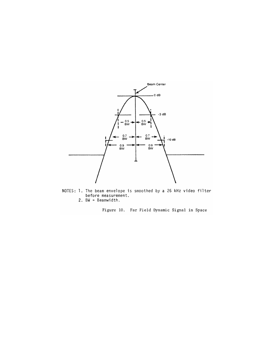
(4)
Antenna far field patterns in the
plane of scan.
On boresight, the azi-
muth antenna mainlobe pattern must
conform to Figure 10, and the beam-
width must be such that, in the in-
stalled environment, no significant lat-
eral reflections of the mainlobe exist
along the approach course. In any case
the beamwidth must not exceed three
degrees. Anywhere within coverage the
¥
3 dB width of the antenna mainlobe,
while scanning normally, must not be
less than 25 microseconds (0.5 degree)
or greater than 250 microseconds (5 de-
grees). The antenna mainlobe may be
allowed to broaden from the value at
boresight by a factor of 1/cos
q
, where
q
is the angle off boresight. The sidelobe
levels must be as follows:
(i)
Dynamic sidelobe levels.
With the
antenna scanning normally, the dy-
namic sidelobe level that is detected by
a receiver at any point within the pro-
portional coverage sector must be
down at least 10 dB from the peak of
the main beam. Outside the coverage
sector, the radiation from the scanning
beam antenna must be of such a nature
that receiver warning will not be re-
moved or suitable OCI signals must be
provided.
(ii)
Effective sidelobe levels.
With the
antenna scanning normally, the
sidelobe levels in the plane of scan
must be such that, in the installed en-
vironment, the CMN contributed by
sidelobe reflections will not exceed the
angular equivalent of 9 feet at ap-
proach reference datum over the re-
quired range of aircraft approach
speeds.
881
Federal Aviation Administration, DOT
§ 171.313
(5)
Antenna far field pattern in the
vertical plane.
The azimuth antenna
free space radiation pattern below the
horizon must have a slope of at least
¥
8 dB/degree at the horizon and all
sidelobes below the horizon must be at
least 13 dB below the pattern peak. The
antenna radiation pattern above the
horizon must satisfy both the system
coverage requirements and the spu-
rious radiation requirement.
(6)
Data antenna.
The data antenna
must have horizontal and vertical pat-
terns as required for its function.
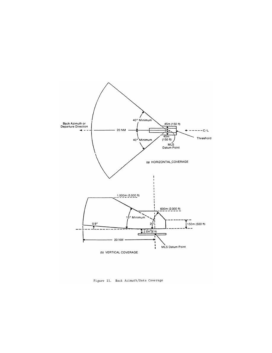
(g)
Back azimuth coverage require-
ments.
The back azimuth equipment
where used must provide guidance in-
formation in at least the following vol-
ume of space (see Figure 11):
882
14 CFR Ch. I (1–1–24 Edition)
§ 171.313
(1) Horizontally within a sector
±
40
degrees about the runway centerline
originating at the back azimuth
ground equipment antenna and extend-
ing in the direction of the missed ap-
proach at least to 20 nautical miles
from the runway stop end. The min-
imum proportional guidance sector
must be
±
10 degrees about the runway
centerline. Clearance signals must be

883
Federal Aviation Administration, DOT
§ 171.313
used to provide the balance of the re-
quired coverage where the proportional
sector is less than
±
40 degrees.
(2) Vertically in the runway region
between:
(i) A horizontal surface 2.5 meters (8
feet) above the farthest point of run-
way centerline which is in line of sight
of the azimuth antenna, and,
(ii) A conical surface originating at
the azimuth ground equipment antenna
inclined at 20 degrees above the hori-
zontal up to a height of 600 meters (2000
feet).
(3) Vertically in the back azimuth re-
gion between:
(i) A conical surface originating 2.5
meters (8 feet) above the runway stop
end, included at 0.9 degree above the
horizontal, and,
(ii) A conical surface orginating at
the missed approach azimuth ground
equipment antenna, inclined at 15 de-
grees above the horizontal up to a
height of 1500 meters (5000 feet).
(iii) Where obstacles penetrate the
lower coverage limits, coverage need be
provided only to minimum line of
sight.
(4) Within the back azimuth coverage
sector defined in paragraph (q) (1), (2),
and (3) of this section the power den-
sities must not be less than those
shown in Table 9, but the equipment
design must also allow for:
(i) Transmitter power degradation
from normal
¥
1.5 dB.
(ii) Rain loss of
¥
2.2 dB at the longi-
tudinal coverage extremes.
(h)
Back azimuth siting.
The back azi-
muth equipment antenna must:
(1) Normally be located on the exten-
sion of the runway centerline at the
threshold end;
(2) Be adjusted so that the vertical
plane containing the zero degree course
line contains the back azimuth ref-
erence datum;
(3) Have minimum height necessary
to comply with the course require-
ments prescribed in paragraph (g) of
this section;
(4) Be located at a distance from the
threshold end that is consistent with
safe obstruction clearance practices;
(5) Not obscure any light of an ap-
proach lighting system; and
(6) Be installed on frangible mounts
or beyond the 300 meter (1000 feet) light
bar.
(i)
Back azimuth antenna coordinates.
The scanning beams transmitted by
the back azimuth equipment may be ei-
ther conical or planar.
(j)
Back azimuth accuracy.
The re-
quirements specified in § 171.313(e)
apply except that the reference point is
the back azimuth reference datum.
(k)
Back azimuth antenna characteris-
tics.
The requirements specified in
§ 171.313(f) apply.
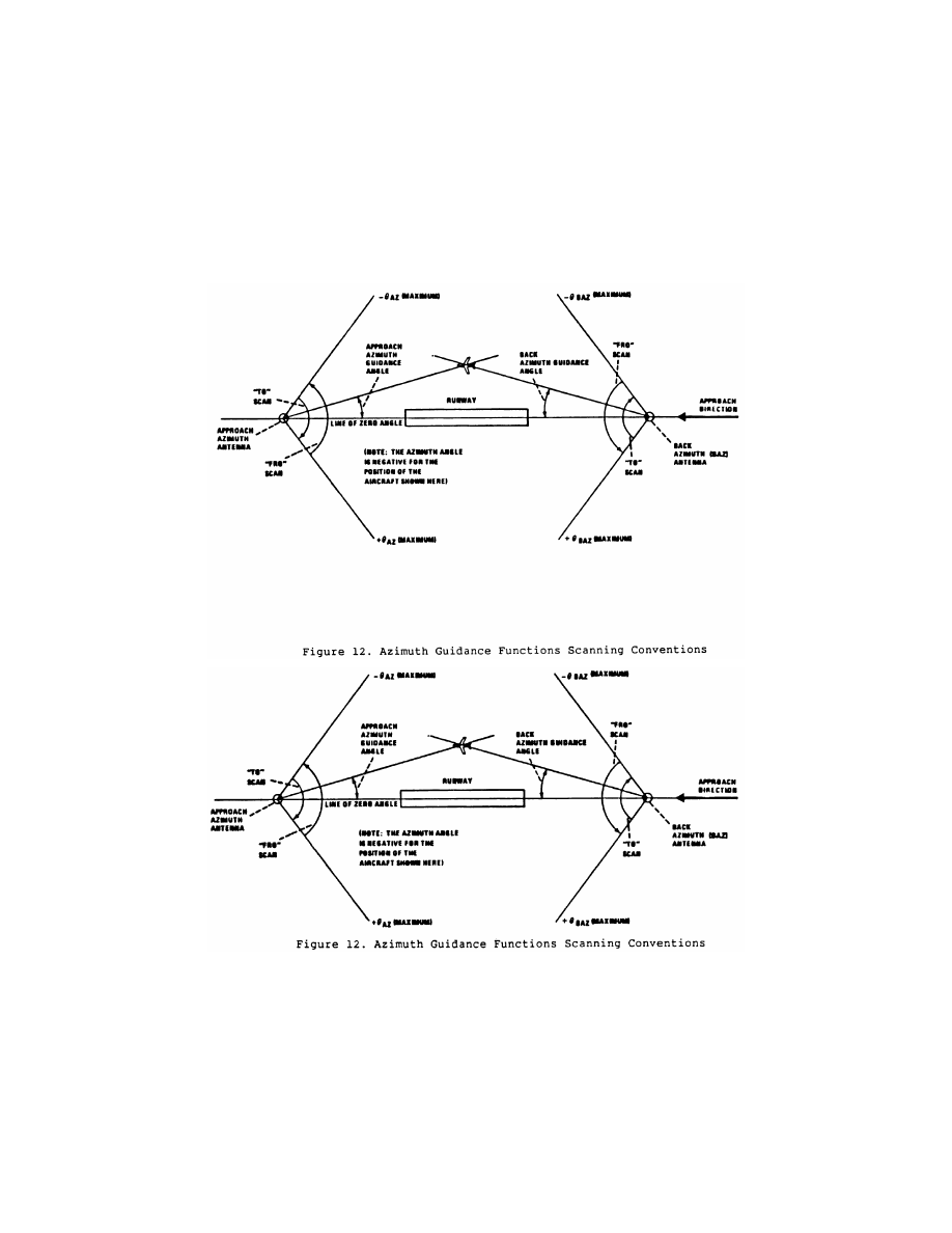
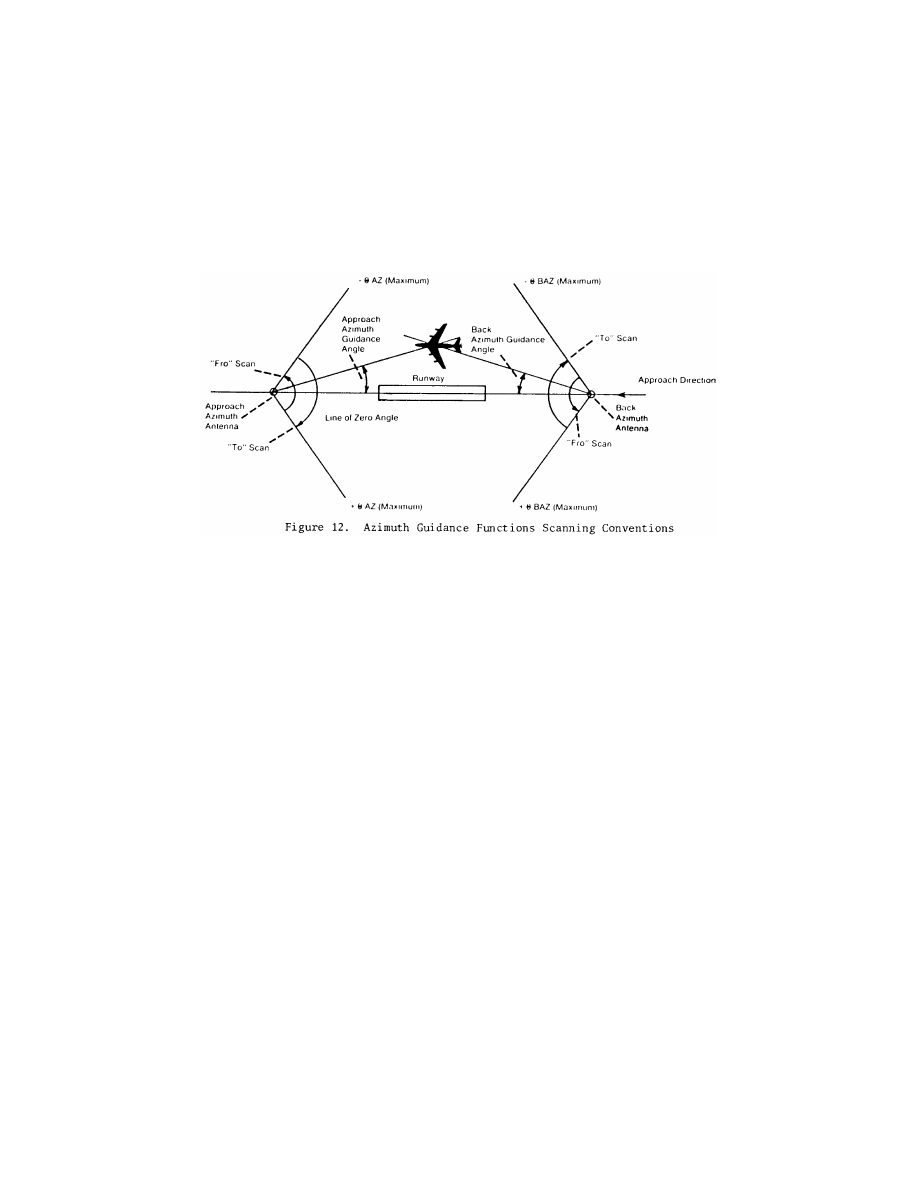
(l)
Scanning conventions.
Figure 12
shows the approach azimuth and back
azimuth scanning conventions.
884
14 CFR Ch. I (1–1–24 Edition)
§ 171.313
885
Federal Aviation Administration, DOT
§ 171.315
(m)
False guidance.
False courses
which can be acquired and tracked by
an aircraft shall not exist anywhere ei-
ther inside or outside of the MLS cov-
erage sector. False courses which exist
outside of the minimum coverage sec-
tor may be suppressed by the use of
OCI.
N
OTE
: False courses may be due to (but not
limited to) MLS airborne receiver acquisi-
tion of the following types of false guidance:
reflections of the scanning beam, scanning
beam antenna sidelobes and grating lobes,
and incorrect clearance.
§ 171.315 Azimuth monitor system re-
quirements.
(a) The approach azimuth or back
azimuth monitor system must cause
the radiation to cease and a warning
must be provided at the designated
control point if any of the following
conditions persist for longer than the
periods specified:
(1) There is a change in the ground
equipment contribution to the mean
course error component such that the
path following error at the reference
datum or in the direction of any azi-
muth radial, exceeds the limits speci-
fied in §§ 171.313(e)(1) or 171.313(j) for a
period of more than one second.
N
OTE
: The above requirement and the re-
quirement to limit the ground equipment
mean error to
±
10 ft. can be satisfied by the
following procedure. The integral monitor
alarm limit should be set to the angular
equivalent of
±
10 ft. at the approach ref-
erence datum. This will limit the electrical
component of the mean course error to
±
10
ft. The field monitor alarm limit should be
set such that with the mean course error at
the alarm limit the total allowed PFE is not
exceeded on any commissioned approach
course from the limit of coverage to an alti-
tude of 100 feet.
(2) There are errors in two consecu-
tive transmissions of Basic Data Words
1, 2, 4 or 5.
(3) There is a reduction in the radi-
ated power to a level not less than that
specified in §§ 171.313(a)(4) or
171.313(g)(4) for a period of more than
one second.
(4) There is an error in the preamble
DPSK transmissions which occurs
more than once in any one second pe-
riod.
(5) There is an error in the time divi-
sion multiplex synchronization of a
particular azimuth function that the
requirement specified in § 171.311(e) is
not satisfied and if this condition per-
sists for more than one second.
(6) A failure of the monitor is de-
tected.
(b) Radiation of the following
fuctions must cease and a warning pro-
vided at the designated control point if
there are errors in 2 consecutive trans-
missions:
(1) Morse Code Identification,
(2) Basic Data Words 3 and 6,
(3) Auxiliary Data Words.