
814
14 CFR Ch. I (1–1–24 Edition)
§ 170.11
observed air traffic which may be in
such proximity to the position or in-
tended route of flight of their aircraft
to warrant attention.
Traffic pattern
means the flow of air-
craft operating on and in the vicinity
of an airport during specified wind con-
ditions as established by appropriate
authority.
VFR traffic
means aircraft operated
solely in accordance with Visual Flight
Rules.
Visual flight rules
(VFR) means rules
that govern the procedures for con-
ducting flight under visual conditions.
The term ‘‘VFR’’ is also used in the
United States to indicate weather con-
ditions that are equal to or greater
than minimum VFR requirements. In
addition, ‘‘VFR’’ is used by pilots and
controllers to indicate the type of
flight plan.
Visual meteorological conditions
(VMC)
means meteorological conditions ex-
pressed in terms of visibility, distance
from clouds, and ceiling equal to or
better than specified minima.
[56 FR 341, Jan. 3, 1991, as amended by Amdt.
170–3, 66 FR 21067, Apr. 27, 2001; Docket FAA–
2017–0733, Amdt. 170–4, 82 FR 34400, July 25,
2017]
Subpart B—Airport Traffic Control
Towers
§ 170.11 Scope.
This subpart sets forth establishment
and discontinuance criteria for Airport
Traffic Control Towers.
§ 170.13 Airport Traffic Control Tower
(ATCT) establishment criteria.
(a) The following criteria along with
general facility establishment stand-
ards must be met before an airport can
qualify for an ATCT:
(1) The airport, whether publicly or
privately owned, must be open to and
available for use by the public as de-
fined in the Airport and Airway Im-
provement Act of 1982;
(2) The airport must be recognized by
and contained within the National
Plan of Integrated Airport Systems;
(3) The airport owners/authorities
must have entered into appropriate as-
surances and covenants to guarantee
that the airport will continue in oper-
ation for a long enough period to per-
mit the amortization of the ATCT in-
vestment;
(4) The FAA must be furnished appro-
priate land without cost for construc-
tion of the ATCT; and
(5) The airport must meet the ben-
efit-cost ratio criteria specified herein
utilizing three consecutive FAA annual
counts and projections of future traffic
during the expected life of the tower fa-
cility. (An FAA annual count is a fiscal
year or a calendar year activity sum-
mary. Where actual traffic counts are
unavailable or not recorded, ade-
quately documented FAA estimates of
the scheduled and nonscheduled activ-
ity may be used.)
(b) An airport meets the establish-
ment criteria when it satisfies para-
graphs (a)(1) through (a)(5) of this sec-
tion and its benefit-cost ratio equals or
exceeds one. As defined in § 170.3 of this
part, the benefit-cost ratio is the ratio
of the present value of the ATCT life
cycle benefits (BPV) to the present
value of ATCT life cycle costs (CPV).
BPV/CPV
≥
1.0
(c) The satisfaction of all the criteria
listed in this section does not guar-
antee that the airport will receive an
ATCT.
§ 170.15 ATCT discontinuance criteria.
An ATCT will be subject to dis-
continuance when the continued oper-
ation and maintenance costs less ter-
mination costs (CMPV) of the ATCT
exceed the present value of its remain-
ing life-cycle benefits (BPV):
BPV/CMPV<1.0
Subpart C
[
Reserved
]
PART 171—NON-FEDERAL
NAVIGATION FACILITIES
Subpart A—VOR Facilities
Sec.
171.1
Scope.
171.3
Requests for IFR procedure.
171.5
Minimum requirements for approval.
171.7
Performance requirements.
171.9
Installation requirements.
171.11
Maintenance and operations require-
ments.
171.13
Reports.

815
Federal Aviation Administration, DOT
§ 171.1
Subpart B—Nondirectional Radio Beacon
Facilities
171.21
Scope.
171.23
Requests for IFR procedure.
171.25
Minimum requirements for approval.
171.27
Performance requirements.
171.29
Installation requirements.
171.31
Maintenance and operations require-
ments.
171.33
Reports.
Subpart C—Instrument Landing System
(ILS) Facilities
171.41
Scope.
171.43
Requests for IFR procedure.
171.45
Minimum requirements for approval.
171.47
Performance requirements.
171.49
Installation requirements.
171.51
Maintenance and operations require-
ments.
171.53
Reports.
Subpart D—True Lights
171.61
Air navigation certificate: Revoca-
tion and termination.
Subpart E—General
171.71
Materials incorporated by reference.
171.73
Alternative forms of reports.
171.75
Submission of requests.
Subpart F—Simplified Directional Facility
(SDF)
171.101
Scope.
171.103
Requests for IFR procedure.
171.105
Minimum requirements for approval.
171.107
Definition.
171.109
Performance requirements.
171.111
Ground standards and tolerances.
171.113
Installation requirements.
171.115
Maintenance and operations require-
ments.
171.117
Reports.
Subpart G—Distance Measuring Equipment
(DME)
171.151
Scope.
171.153
Requests for IFR procedure.
171.155
Minimum requirements for approval.
171.157
Performance requirements.
171.159
Installation requirements.
171.161
Maintenance and operations require-
ments.
171.163
Reports.
Subpart H—VHF Marker Beacons
171.201
Scope.
171.203
Requests for IFR procedure.
171.205
Minimum requirements for approval.
171.207
Performance requirements.
171.209
Installation requirements.
171.211
Maintenance and operations require-
ments.
171.213
Reports.
Subpart I—Interim Standard Microwave
Landing System (ISMLS)
171.251
Scope.
171.253
Definitions.
171.255
Requests for IFR procedures.
171.257
Minimum requirements for approval.
171.259
Performance requirements: General.
171.261
Localizer performance requirements.
171.263
Localizer automatic monitor sys-
tem.
171.265
Glide path performance require-
ments.
171.267
Glide path automatic monitor sys-
tem.
171.269
Marker beacon performance require-
ments.
171.271
Installation requirements.
171.273
Maintenance and operations require-
ments.
171.275
Reports.
Subpart J—Microwave Landing System
(MLS)
171.301
Scope.
171.303
Definitions.
171.305
Requests for IFR procedure.
171.307
Minimum requirements for approval.
171.309
General requirements.
171.311
Signal format requirements.
171.313
Azimuth performance requirements.
171.315
Azimuth monitor system require-
ments.
171.317
Approach elevation performance re-
quirements.
171.319
Approach elevation monitor system
requirements.
171.321
DME and marker beacon perform-
ance requirements.
171.323
Fabrication and installation require-
ments.
171.325
Maintenance and operations require-
ments.
171.327
Operational records.
A
UTHORITY
: 49 U.S.C. 106(g), 40103–40107,
40109, 40113, 44502, 44701–44702, 44708–44709,
44711, 44719–44721, 45303, 46308.
S
OURCE
: Docket No. 5034, 29 FR 11337, Aug.
6, 1964, unless otherwise noted.
Subpart A—VOR Facilities
§ 171.1 Scope.
This subpart sets forth minimum re-
quirements for the approval and oper-
ation on non-Federal VOR facilities
that are to be involved in the approval

816
14 CFR Ch. I (1–1–24 Edition)
§ 171.3
of instrument flight rules and air traf-
fic control procedures related to those
facilities.
[Doc. No. 5034, 29 FR 11337, Aug. 6, 1964, as
amended by Amdt. 171–2, 31 FR 5408, Apr. 6,
1966; Amdt. 171–7, 35 FR 12711, Aug. 11, 1970]
§ 171.3 Requests for IFR procedure.
(a) Each person who requests an IFR
procedure based on a VOR facility that
he owns must submit the following in-
formation with that request:
(1) A description of the facility and
evidence that the equipment meets the
performance requirements of § 171.7 and
is installed in accordance with § 171.9.
(2) A proposed procedure for oper-
ating the facility.
(3) A proposed maintenance organiza-
tion and maintenance manual that
meets the requirements of § 171.11.
(4) A statement of intention to meet
the requirements of this subpart.
(5) A showing that the facility has an
acceptable level of operational reli-
ability and an acceptable standard of
performance. Previous equivalent oper-
ational experience with a facility with
identical design and operational char-
acteristics will be considered in show-
ing compliance with this paragraph.
(b) After the FAA inspects and evalu-
ates the facility, it advises the owner
of the results and of any required
changes in the facility or the mainte-
nance manual or maintenance organi-
zation. The owner must then correct
the deficiencies, if any, and operate the
facility for an in-service evaluation by
the FAA.
[Doc. No. 5034, 29 FR 11337, Aug. 6, 1964, as
amended by Amdt. 171–7, 35 FR 12711, Aug. 11,
1970]
§ 171.5 Minimum requirements for ap-
proval.
(a) The following are the minimum
requirements that must be met before
the FAA will approve an IFR procedure
for a non-Federal VOR:
(1) The facility’s performance, as de-
termined by air and ground inspection,
must meet the requirements of § 171.7.
(2) The installation of the equipment
must meet the requirements of § 171.9.
(3) The owner must agree to operate
and maintain the facility in accord-
ance with § 171.11.
(4) The owner must agree to furnish
periodic reports, as set forth in § 171.13,
and must agree to allow the FAA to in-
spect the facility and its operation
whenever necessary.
(5) The owner must assure the FAA
that he will not withdraw the facility
from service without the permission of
the FAA.
(6) The owner must bear all costs of
meeting the requirements of this sec-
tion and of any flight or ground inspec-
tions made before the facility is com-
missioned, except that the Federal
Aviation Administration may bear cer-
tain of these costs subject to budgetary
limitations and policy established by
the Administrator.
(b) If the applicant for approval
meets the requirements of paragraph
(a) of this section, the FAA commis-
sions the facility as a prerequisite to
its approval for use in an IFR proce-
dure. The approval is withdrawn at any
time the facility does not continue to
meet those requirements.
[Doc. No. 5034, 29 FR 11337, Aug. 6, 1964, as
amended by Amdt. 171–6, 35 FR 10288, June
24, 1970]
§ 171.7 Performance requirements.
(a) The VOR must perform in accord-
ance with the ‘‘International Stand-
ards and Recommended Practices,
Aeronautical Telecommunications,’’
Part I, paragraph 3.3 (Annex 10 to the
Convention on International Civil
Aviation), except that part of para-
graph 3.3.2.1 specifying a radio fre-
quency tolerance of 0.005 percent, and
that part of paragraph 3.3.7 requiring
removal of only the bearing informa-
tion. In place thereof, the frequency
tolerance of the radio frequency carrier
must not exceed plus or minus 0.002
percent, and all radiation must be re-
moved during the specified deviations
from established conditions and during
periods of monitor failure.
(b) Ground inspection consists of an
examination of the design features of
the equipment to determine that there
will not be conditions that will allow
unsafe operations because of compo-
nent failure or deterioration.

817
Federal Aviation Administration, DOT
§ 171.11
(c) The monitor is checked periodi-
cally, during the in-service test evalua-
tion period, for calibration and sta-
bility The tests are made with a stand-
ard ‘‘Reference and variable phase sig-
nal generator’’ and associated test
equipment, including an oscilloscope
and portable field detector. In general,
the ground check is conducted in
accord- ance with section 8.4 of FAA
Handbook AF P 6790.9 ‘‘Maintenance
Instruction for VHF Omniranges’’,
adapted for the facility concerned.
(d) Flight tests to determine the fa-
cility’s adequacy for operational re-
quirements and compliance with appli-
cable ‘‘Standards and Recommended
Practices’’ are conducted in accordance
with the ‘‘U.S. Standard Flight Inspec-
tion Manual’’, particularly section 201.
(e) After January 1, 1975, the owner of
the VOR shall modify the facility to
perform in accordance with paragraph
3.3.5.7 of Annex 10 to the Convention on
International Civil Aviation within 180
days after receipt of notice from the
Administrator that 50 kHz channel
spacing is to be implemented in the
area and that a requirement exists for
suppression of 9960 Hz subcarrier
harmonics.
[Doc. No. 5034, 29 FR 11337, Aug. 6, 1964, as
amended by Amdt. 171–7, 35 FR 12711, Aug. 11,
1970; Amdt. 171–9, 38 FR 28557, Oct. 15, 1973]
§ 171.9 Installation requirements.
(a) The facility must be installed ac-
cording to accepted good engineering
practices, applicable electric and safe-
ty codes, and the installation must
meet at least the Federal Communica-
tion Commission’s licensing require-
ments.
(b) The facility must have a reliable
source of suitable primary power, ei-
ther from a power distribution system
or locally generated, with a supple-
mental standby system, if needed.
(c) Dual transmitting equipment
with automatic changeover is preferred
and may be required to support certain
IFR procedures.
(d) There must be a means for deter-
mining, from the ground, the perform-
ance of the equipment, including the
antenna, initially and periodically.
(e) A facility intended for use as an
instrument approach aid for an airport
must have or be supplemented by (de-
pending on circumstances) the fol-
lowing ground-air or landline commu-
nications services:
(1) At facilities outside of and not im-
mediately adjacent to controlled air-
space, there must be ground-air com-
munications from the airport served by
the facility. Separate communications
channels are acceptable.
(2) At facilities within or imme-
diately adjacent to controlled airspace,
there must be the ground-air commu-
nications required by paragraph (e)(1)
of this section and reliable communica-
tions (at least a landline telephone)
from the airport to the nearest FAA
air traffic control or communication
facility.
Paragraphs (e) (1) and (2) of this sec-
tion are not mandatory at airports
where an adjacent FAA facility can
communicate with aircraft on the
ground at the airport and during the
entire proposed instrument approach
procedure. In addition, at low traffic
density airports within or immediately
adjacent to controlled airspace and
where extensive delays are not a fac-
tor, the requirements of paragraphs (e)
(1) and (2) of this section may be re-
duced to reliable communications (at
least a landline telephone) from the
airport to the nearest FAA air traffic
control or communication facility, if
an adjacent FAA facility can commu-
nicate with aircraft during the pro-
posed instrument approach procedure,
at least down to the minimum en route
altitude for the controlled airspace
area.
[Doc. No. 5034, 29 FR 11337, Aug. 6, 1964, as
amended by Amdt. 171–7, 35 FR 12711, Aug. 11,
1970; Amdt. 171–16, 56 FR 65664, Dec. 17, 1991]
§ 171.11 Maintenance and operations
requirements.
(a) The owner of the facility must es-
tablish an adequate maintenance sys-
tem and provide qualified maintenance
personnel to maintain the facility at
the level attained at the time it was
commissioned. Each person who main-
tains a facility must meet at least the
Federal Communications Commission’s
licensing requirements and show that
he has the special knowledge and skills

818
14 CFR Ch. I (1–1–24 Edition)
§ 171.11
needed to maintain the facility includ-
ing proficiency in maintenance proce-
dures and the use of specialized test
equipment.
(b) The owner must prepare, and ob-
tain FAA approval of, an operations
and maintenance manual that sets
forth mandatory procedures for oper-
ations, preventive maintenance, and
emergency maintenance, including in-
structions on each of the following:
(1) Physical security of the facility.
(2) Maintenance and operations by
authorized persons only.
(3) FCC licensing requirements for
operating and maintenance personnel.
(4) Posting of licenses and signs.
(5) Relations between the facility and
FAA air traffic control facilities, with
a description of the boundaries of con-
trolled airspace over or near the facil-
ity, instructions for relaying air traffic
control instructions and information
(if applicable), and instructions for the
operation of an air traffic advisory
service if the VOR is located outside of
controlled airspace.
(6) Notice to the Administrator of
any suspension of service.
(7) Detailed and specific maintenance
procedures and servicing guides stating
the frequency of servicing.
(8) Air-ground communications, if
provided, expressly written or incor-
porating appropriate sections of FAA
manuals by reference.
(9) Keeping of station logs and other
technical reports, and the submission
of reports required by § 171.13.
(10) Monitoring of the facility.
(11) Inspections by United States per-
sonnel.
(12) Names, addresses, and telephone
numbers of persons to be notified in an
emergency.
(13) Shutdowns for routine mainte-
nance and issue of ‘‘Notices to Airmen’’
for routine or emergency shutdowns
(private use facilities may omit the
‘‘Notices to Airmen’’).
(14) An explanation of the kinds of
activity (such as construction or grad-
ing) in the vicinity of the facility that
may require shutdown or recertifi-
cation of the facility by FAA flight
check.
(15) Procedures for conducting a
ground check of course accuracy.
(16) Commissioning of the facility.
(17) An acceptable procedure for
amending or revising the manual.
(18) The following information con-
cerning the facility:
(i) Location by latitude and lon-
gitude to the nearest second, and its
position with respect to airport lay-
outs.
(ii) The type, make, and model of the
basic radio equipment that will provide
the service.
(iii) The station power emission and
frequency.
(iv) The hours of operation.
(v) Station identification call letters
and method of station identification,
whether by Morse code or recorded
voice announcement, and the time
spacing of the identification.
(vi) A description of the critical parts
that may not be changed, adjusted, or
repaired without an FAA flight check
to confirm published operations.
(c) The owner shall make a ground
check of course accuracy each month
in accordance with procedures ap-
proved by the FAA at the time of com-
missioning, and shall report the results
of the checks as provided in § 171.13.
(d) If the owner desires to modify the
facility, he must submit the proposal
to the FAA and may not allow any
modifications to be made without spe-
cific approval.
(e) The owner’s maintenance per-
sonnel must participate in initial in-
spections made by the FAA. In the case
of subsequent inspections, the owner or
his representative shall participate.
(f) Whenever it is required by the
FAA, the owner shall incorporate im-
provements in VOR maintenance
brought about by progress in the state
of the art. In addition, he shall provide
a stock of spare parts, including vacu-
um tubes, of such a quantity to make
possible the prompt replacement of
components that fail or deteriorate in
service.
(g) The owner shall provide all ap-
proved test instruments needed for
maintenance of the facility.
(h) The owner shall close the facility
upon receiving two successive pilot re-
ports of its malfunctioning.
[Doc. No. 5034, 29 FR 11337, Aug. 6, 1964, as
amended by Amdt. 171–2, 31 FR 5408, Apr. 6,
1966]

819
Federal Aviation Administration, DOT
§ 171.23
§ 171.13 Reports.
The owner of each facility to which
this subpart applies shall make the fol-
lowing reports on forms furnished by
the FAA, at the times indicated, to the
FAA Regional office for the area in
which the facility is located:
(a)
Record of meter readings and adjust-
ments
(
Form FAA–198
). To be filled out
by the owner with the equipment ad-
justments and meter readings as of the
time of commissioning, with one copy
to be kept in the permanent records of
the facility and two copies to the ap-
propriate Regional office of the FAA.
The owner shall revise the form after
any major repair, modernization, or re-
turning, to reflect an accurate record
of facility operation and adjustment.
(b)
Facility maintenance log
(
FAA Form
6003–1
). This form is a permanent
record of all equipment malfunctioning
met in maintaining the facility, in-
cluding information on the kind of
work and adjustments made, equip-
ment failures, causes (if determined),
and corrective action taken. The owner
shall keep the original of each report
at the facility and send a copy to the
appropriate Regional office of the FAA
at the end of the month in which it is
prepared.
(c)
Radio equipment operation record
(
Form FAA–418
). To contain a complete
record of meter readings, recorded on
each scheduled visit to the facility.
The owner shall keep the original of
each month’s record at the facility and
send a copy of it to the appropriate Re-
gional office of the FAA.
(d) [Reserved]
(e)
VOR ground check error data
(
Forms FAA–2396 and 2397
). To contain
results of the monthly course accuracy
ground check in accordance with FAA
Handbook AF P 6790.9 ‘‘Maintenance
Instructions for VHF Omniranges’’.
The owner shall keep the originals in
the facility and send a copy of each
form to the appropriate Regional office
of the FAA on a monthly basis.
(49 U.S.C. 1348)
[Doc. No. 5034, 29 FR 11337, Aug. 6, 1964, as
amended by Amdt. 171–5, 34 FR 15245, Sept.
30, 1969; Amdt. 171–10, 40 FR 36110, Aug. 19,
1975]
Subpart B—Nondirectional Radio
Beacon Facilities
§ 171.21 Scope.
(a) This subpart sets forth minimum
requirements for the approval and op-
eration of non-Federal, nondirectional
radio beacon facilities that are to be
involved in the approval of instrument
flight rules and air traffic control pro-
cedures related to those facilities.
(b) A nondirectional radio beacon
(‘‘H’’ facilities domestically—NDB fa-
cilities internationally) radiates a con-
tinuous carrier of approximately equal
intensity at all azimuths. The carrier
is modulated at 1020 cycles per second
for station identification purposes.
[Doc. No. 5034, 29 FR 11337, Aug. 6, 1964, as
amended by Amdt. 171–2, 31 FR 5408, Apr. 6,
1966; Amdt. 171–7, 35 FR 12711, Aug. 11, 1970]
§ 171.23 Requests for IFR procedure.
(a) Each person who requests an IFR
procedure based on a nondirectional
radio beacon facility that he owns
must submit the following information
with that request:
(1) A description of the facility and
evidence that the equipment meets the
performance requirements of § 171.27
and is installed in accordance with
§ 171.29.
(2) A proposed procedure for oper-
ating the facility.
(3) A proposed maintenance arrange-
ment and a maintenance manual that
meets the requirements of § 171.31.
(4) A statement of intention to meet
the requirements of this subpart.
(5) A showing that the facility has an
acceptable level of operational reli-
ability and an acceptable standard of
performance. Previous equivalent oper-
ational experience with a facility with
identical design and operational char-
acteristics will be considered in show-
ing compliance with this subparagraph.
(b) After the FAA inspects and evalu-
ates the facility, it advises the owner
of the results and of any required
changes in the facility or the mainte-
nance manual or maintenance organi-
zation. The owner must then correct
the deficiencies, if any, and operate the

820
14 CFR Ch. I (1–1–24 Edition)
§ 171.25
facility for an in-service evaluation by
the FAA.
[Doc. No. 5034, 29 FR 11337, Aug. 6, 1964, as
amended by Amdt. 171–7, 35 FR 12711, Aug. 11,
1970]
§ 171.25 Minimum requirements for ap-
proval.
(a) The following are the minimum
requirements that must be met before
the FAA will approve an IFR procedure
for a non-Federal, nondirectional radio
beacon facility under this subpart:
(1) The facility’s performances, as de-
termined by air and ground inspection,
must meet the requirements of § 171.27.
(2) The installation of the equipment
must meet the requirements of § 171.29.
(3) The owner must agree to operate
and maintain the facility in accord-
ance with § 171.31.
(4) The owner must agree to furnish
periodic reports, as set forth in § 171.33,
and agree to allow the FAA to inspect
the facility and its operation whenever
necessary.
(5) The owner must assure the FAA
that he will not withdraw the facility
from service without the permission of
the FAA.
(6) The owner must bear all costs of
meeting the requirements of this sec-
tion and of any flight or ground inspec-
tions made before the facility is com-
missioned, except that the Federal
Aviation Administration may bear cer-
tain of these costs subject to budgetary
limitations and policy established by
the Administrator.
(b) If the applicant for approval
meets the requirements of paragraph
(a) of this section, the FAA commis-
sions the facility as a prerequisite to
its approval for use in an IFR proce-
dure. The approval is withdrawn at any
time the facility does not continue to
meet those requirements. In addition,
the facility may be de-commissioned
whenever the frequency channel is
needed for higher priority common sys-
tem service.
[Doc. No. 5034, 29 FR 11337, Aug. 6, 1964, as
amended by Amdt. 171–6, 35 FR 10288, June
24, 1970]
§ 171.27 Performance requirements.
(a) The facility must meet the per-
formance requirements set forth in the
‘‘International Standards and Rec-
ommended Practices, Aeronautical
Telecommunications, Part I, paragraph
3.4’’ (Annex 10 to the Convention on
International Civil Aviation), except
that identification by on-off keying of
a second carrier frequency, separated
from the main carrier by 1020 Hz plus
or minus 50 Hz, is also acceptable.
(b) The facility must perform in ac-
cordance with recognized and accepted
good electronic engineering practices
for the desired service.
(c) Ground inspection consists of an
examination of the design features of
the equipment to determine (based on
recognized and accepted good engineer-
ing practices) that there will not be
conditions that will allow unsafe oper-
ations because of component failure or
deterioration.
(d) Flight tests to determine the fa-
cility’s adequacy for operational re-
quirements and compliance with appli-
cable ‘‘Standards and Recommended
Practices’’ are conducted in accord-
ance with the ‘‘U.S. Standard Flight
Inspection Manual’’, particularly sec-
tion 207. The original test is made by
the FAA and later tests shall be made
under arrangements, satisfactory to
the FAA, that are made by the owner.
[Doc. No. 5034, 29 FR 11337, Aug. 6, 1964, as
amended by Amdt. 171–7, 35 FR 12711, Aug. 11,
1970]
§ 171.29 Installation requirements.
(a) The facility must be installed ac-
cording to accepted good engineering
practices, applicable electric and safe-
ty codes, and FCC licensing require-
ments.
(b) The facility must have a reliable
source of suitable primary power.
(c) Dual transmitting equipment may
be required to support some IFR proce-
dures.
(d) A facility intended for use as an
instrument approach aid for an airport
must have or be supplemented by (de-
pending on the circumstances) the fol-
lowing ground-air or landline commu-
nications services:
(1) At facilities outside of and not im-
mediately adjacent to controlled air-
space, there must be ground-air com-
munications from the airport served by
the facility. Voice on the aid con-
trolled from the airport is acceptable.

821
Federal Aviation Administration, DOT
§ 171.31
(2) At facilities within or imme-
diately adjacent to controlled airspace,
there must be the ground-air commu-
nications required by paragraph (d)(1)
of this section and reliable communica-
tions (at least a landline telephone)
from the airport to the nearest FAA
air traffic control or communication
facility.
Paragraphs (d) (1) and (2) of this sec-
tion are not mandatory at airports
where an adjacent FAA facility can
communicate with aircraft on the
ground at the airport and during the
entire proposed instrument approach
procedure. In addition, at low traffic
density airports within or immediately
adjacent to controlled airspace, and
where extensive delays are not a fac-
tor, the requirements of paragraphs (d)
(1) and (2) of this section may be re-
duced to reliable communications (at
least a landline telephone) from the
airport to the nearest FAA air traffic
control or communications facility, if
an adjacent FAA facility can commu-
nicate with aircraft during the pro-
posed instrument approach procedure,
at least down to the minimum en route
altitude for the controlled airspace
area.
[Doc. No. 5034, 29 FR 11337, Aug. 6, 1964, as
amended by Amdt. 171–16, 56 FR 65664, Dec.
17, 1991]
§ 171.31 Maintenance and operations
requirements.
(a) The owner of the facility must es-
tablish an adequate maintenance sys-
tem and provide qualified maintenance
personnel to maintain the facility at
the level attained at the time it was
commissioned. Each person who main-
tains a facility must meet at least the
Federal Communications Commission’s
licensing requirements and show that
he has the special knowledge and skills
needed to maintain the facility includ-
ing proficiency in maintenance proce-
dures and the use of specialized test
equipment.
(b) The owner must prepare, and ob-
tain approval of, an operations and
maintenance manual that sets forth
mandatory procedures for operations,
preventive maintenance, and emer-
gency maintenance, including instruc-
tions on each of the following:
(1) Physical security of the facility.
(2) Maintenance and operations by
authorized persons only.
(3) FCC licensing requirements for
operating and maintenance personnel.
(4) Posting of licenses and signs.
(5) Relations between the facility and
FAA air traffic control facilities, with
a description of the boundaries of con-
trolled airspace over or near the facil-
ity, instructions for relaying air traffic
control instructions and information
(if applicable), and instructions for the
operation of an air traffic advisory
service if the facility is located outside
of controlled airspace.
(6) Notice to the Administrator of
any suspension of service.
(7) Detailed arrangements for main-
tenance flight inspection and servicing
stating the frequency of servicing.
(8) Air-ground communications, if
provided, expressly written or incor-
porating appropriate sections of FAA
manuals by reference.
(9) Keeping of station logs and other
technical reports, and the submission
of reports required by § 171.33.
(10) Monitoring of the facility, at
least once each half hour, to assure
continuous operation.
(11) Inspections by United States per-
sonnel.
(12) Names, addresses, and telephone
numbers of persons to be notified in an
emergency.
(13) Shutdowns for routine mainte-
nance and issue of ‘‘Notices to Airmen’’
for routine or emergency shutdowns
(private use facilities may omit the
‘‘Notices to Airmen’’).
(14) Commissioning of the facility.
(15) An acceptable procedure for
amending or revising the manual.
(16) The following information con-
cerning the facility:
(i) Location by latitude and lon-
gitude to the nearest second, and its
position with respect to airport lay-
outs.
(ii) The type, make, and model of the
basic radio equipment that will provide
the service.
(iii) The station power emission and
frequency.
(iv) The hours of operation.
(v) Station identification call letters
and method of station identification,
whether by Morse code or recorded

822
14 CFR Ch. I (1–1–24 Edition)
§ 171.33
voice announcement, and the time
spacing of the identification.
(c) If the owner desires to modify the
facility, he must submit the proposal
to the FAA and meet applicable re-
quirements of the FCC.
(d) The owner’s maintenance per-
sonnel must participate in initial in-
spections made by the FAA. In the case
of subsequent inspections, the owner or
his representative shall participate.
(e) The owner shall provide a stock of
spare parts, including vacuum tubes, of
such a quantity to make possible the
prompt replacement of components
that fail or deteriorate in service.
(f) The owner shall close the facility
upon receiving two successive pilot re-
ports of its malfunctioning.
[Doc. No. 5034, 29 FR 11337, Aug. 6, 1964, as
amended by Amdt. 171–2, 31 FR 5408, Apr. 6,
1966]
§ 171.33 Reports.
The owner of each facility to which
this subpart applies shall make the fol-
lowing reports, at the times indicated,
to the FAA Regional office for the area
in which the facility is located:
(a)
Record of meter readings and adjust-
ments
(
Form FAA–198
). To be filled out
by the owner or his maintenance rep-
resentative with the equipment adjust-
ments and meter readings as of the
time of commissioning, with one copy
to be kept in the permanent records of
the facility and two copies to the ap-
propriate Regional Office of the FAA.
The owner shall revise the form after
any major repair, modernization, or re-
turning, to reflect an accurate record
of facility operation and adjustment.
(b)
Facility maintenance log
(
FAA Form
6030–1
). This form is a permanent
record of all equipment malfunctioning
met in maintaining the facility, in-
cluding information on the kind of
work and adjustments made, equip-
ment failures, causes (if determined),
and corrective action taken. The owner
shall keep the original of each report
at the facility and send a copy to the
appropriate Regional Office of the FAA
at the end of the month in which it is
prepared.
(c)
Radio equipment operation record
(
Form FAA–418
). To contain a complete
record of meter readings, recorded on
each scheduled visit to the facility.
The owner shall keep the original of
each month’s record at the facility and
send a copy of it to the appropriate Re-
gional Office of the FAA.
[Doc. No. 5034, 29 FR 11337, Aug. 6, 1964, as
amended by Amdt. 171–10, 40 FR 36110, Aug.
19, 1975]
Subpart C—Instrument Landing
System (ILS) Facilities
§ 171.41 Scope.
This subpart sets forth minimum re-
quirements for the approval and oper-
ation of non-Federal Instrument Land-
ing System (ILS) Facilities that are to
be involved in the approval of instru-
ment flight rules and air traffic control
procedures related to those facilities.
[Doc. No. 5034, 29 FR 11337, Aug. 6, 1964, as
amended by Amdt. 171–2, 31 FR 5408, Apr. 6,
1966; Amdt. 171–7, 35 FR 12711, Aug. 11, 1970]
§ 171.43 Requests for IFR procedure.
(a) Each person who requests an IFR
procedure based on an ILS facility that
he owns must submit the following in-
formation with that request:
(1) A description of the facility and
evidence that the equipment meets the
performance requirements of § 171.47
and is installed in accordance with
§ 171.49.
(2) A proposed procedure for oper-
ating the facility.
(3) A proposed maintenance organiza-
tion and a maintenance manual that
meets the requirements of § 171.51.
(4) A statement of intent to meet the
requirements of this subpart.
(5) A showing that the facility has an
acceptable level of operational reli-
ability and an acceptable standard of
performance. Previous equivalent oper-
ational experience with a facility with
identical design and operational char-
acteristics will be considered in show-
ing compliance with this subparagraph.
(b) After the FAA inspects and evalu-
ates the facility, it advises the owner
of the results and of any required
changes in the facility or the mainte-
nance manual or maintenance organi-
zation. The owner must then correct
the deficiencies, if any, and operate the

823
Federal Aviation Administration, DOT
§ 171.47
facility for an in-service evaluation by
the FAA.
[Doc. No. 5034, 29 FR 11337, Aug. 6, 1964, as
amended by Amdt. 171–7, 35 FR 12711, Aug. 11,
1970]
§ 171.45 Minimum requirements for ap-
proval.
(a) The following are the minimum
requirements that must be met before
the FAA will approve an IFR procedure
for a non-Federal Instrument Landing
System:
(1) The facility’s performance, as de-
termined by air and ground inspection,
must meet the requirements of § 171.47.
(2) The installation of the equipment
must meet the requirements of § 171.49.
(3) The owner must agree to operate
and maintain the facility in accord-
ance with § 171.51.
(4) The owner must agree to furnish
periodic reports, as set forth in § 171.53
and agree to allow the FAA to inspect
the facility and its operation whenever
necessary.
(5) The owner must assure the FAA
that he will not withdraw the facility
from service without the permission of
the FAA.
(6) The owner must bear all costs of
meeting the requirements of this sec-
tion and of any flight or ground inspec-
tions made before the facility is com-
missioned, except that the Federal
Aviation Administration may bear cer-
tain of these costs subject to budgetary
limitations and policy established by
the Administrator.
(b) If the applicant for approval
meets the requirements of paragraph
(a) of this section, the FAA commis-
sions the facility as a prerequisite to
its approval for use in an IFR proce-
dure. The approval is withdrawn at any
time the facility does not continue to
meet those requirements. In addition,
the facility may be de-commissioned
whenever the frequency channel is
needed for higher priority common sys-
tem service.
[Doc. No. 5034, 29 FR 11337, Aug. 6, 1964, as
amended by Amdt. 171–6, 35 FR 10288, June
24, 1970]
§ 171.47 Performance requirements.
(a) The Instrument Landing System
must perform in accordance with the
‘‘International Standards and Rec-
ommended Practices, Aeronautical
Telecommunications, Part I, Para-
graph 3.1’’ (Annex 10 to the Convention
on International Civil Aviation) except
as follows:
(1) The first part of paragraph 3.1.3,
relating to suppression of radiation
wholly or in part in any or all direc-
tions outside the 20-degree sector cen-
tered on the course line to reduce lo-
calizer does not apply.
(2) Radiation patterns must conform
to limits specified in 3.1.3.3 and 3.1.3.4,
but this does not mean that suppres-
sion of radiation to the rear of the an-
tenna array to satisfy difficult siting
positions (as per 3.1.3.1.4) is not al-
lowed. For example, if a reflector
screen for the antenna array is re-
quired to overcome a siting problem,
the area to the rear of the localizer
may be made unusable and should be so
advertised.
(3) A third marker beacon (inner
marker) is not required.
(4) The frequency tolerance of the
radio frequency carrier must not ex-
ceed plus or minus 0.002 percent.
(b) Ground inspection consists of an
examination of the design features of
the equipment to determine that there
will not be conditions that will allow
unsafe operations because of compo-
nent failure or deterioration.
(c) The monitor is checked periodi-
cally, during the in-service test evalua-
tion period, for calibration and sta-
bility. These tests, and ground checks
of glide slope and localizer radiation
characteristics, are conducted in ac-
cordance with FAA Handbooks AF P
6750.1 and AF P 6750.2 ‘‘Maintenance In-
structions for ILS Localizer Equip-
ment’’ and ‘‘Maintenance Instructions
for ILS Glide Slope Equipment’’.
(d) Flight tests to determine the fa-
cility’s adequacy for operational re-
quirements and compliance with appli-
cable ‘‘Standards and Recommended
Practices’’ are conducted in accord-
ance with the ‘‘U.S. Standard Flight
Inspection Manual’’, particularly sec-
tion 217.
[Doc. No. 5034, 29 FR 11337, Aug. 6, 1974, as
amended by Amdt. 171–9, 38 FR 28557, Oct. 15,
1973]

824
14 CFR Ch. I (1–1–24 Edition)
§ 171.49
§ 171.49 Installation requirements.
(a) The facility must be of a perma-
nent nature, located, constructed, and
installed according to ICAO Standards
(Annex 10), accepted good engineering
practices, applicable electric and safe-
ty codes, and FCC licensing require-
ments.
(b) The facility must have a reliable
source of suitable primary power, ei-
ther from a power distribution system
or locally generated. A determination
by the Administrator as to whether a
facility will be required to have stand-
by power for the localizer, glide slope
and monitor accessories to supplement
the primary power, will be made for
each airport based upon operational
minimums and density of air traffic.
(c) A determination by the Adminis-
trator as to whether a facility will be
required to have dual transmitting
equipment with automatic changeover
for localizer and glide slope compo-
nents, will be made for each airport
based upon operational minimums and
density of air traffic.
(d) There must be a means for deter-
mining, from the ground, the perform-
ance of the equipment (including an-
tennae), initially and periodically.
(e) The facility must have, or be sup-
plemented by (depending on the cir-
cumstances) the following ground-air
or landline communications services:
(1) At facilities outside of and not im-
mediately adjacent to controlled air-
space, there must be ground-air com-
munications from the airport served by
the facility. The utilization of voice on
the ILS frequency should be deter-
mined by the facility operator on an
individual basis.
(2) At facilities within or imme-
diately adjacent to controlled airspace,
there must be the ground-air commu-
nications required by paragraph (e)(1)
of this section and reliable communica-
tions (at least a landline telephone)
from the airport to the nearest FAA
air traffic control or communications
facility.
Paragraphs (e)(1) and (e)(2) of this sec-
tion are not mandatory at airports
where an adjacent FAA facility can
communicate with aircraft on the
ground at the airport and during the
entire proposed instrument approach
procedure. In addition, at low traffic
density airports within or immediately
adjacent to controlled airspace, and
where extensive delays are not a fac-
tor, the requirements of paragraphs
(e)(1) and (e)(2) of this section may be
reduced to reliable communications (at
least a landline telephone) from the
airport to the nearest FAA air traffic
control or communications facility, if
an adjacent FAA facility can commu-
nicate with aircraft during the pro-
posed instrument approach procedure
down to the airport surface or at least
to the minimum approach altitude.
[Doc. No. 5034, 29 FR 11337, Aug. 6, 1964, as
amended by Amdt. 171–6, 35 FR 10288, June
24, 1970; Amdt. 171–16, 56 FR 65664, Dec. 17,
1991]
§ 171.51 Maintenance and operations
requirements.
(a) The owner of the facility must es-
tablish an adequate maintenance sys-
tem and provide qualified maintenance
personnel to maintain the facility at
the level attained at the time it was
commissioned. Each person who main-
tains a facility must meet at least the
Federal Communications Commission’s
licensing requirements and show that
he has the special knowledge and skills
needed to maintain the facility includ-
ing proficiency in maintenance proce-
dures and the use of specialized test
equipment.
(b) The owner must prepare, and ob-
tain approval of, an operations and
maintenance manual that sets forth
mandatory procedures for operations,
preventive maintenance, and emer-
gency maintenance, including instruc-
tions on each of the following:
(1) Physical security of the facility.
(2) Maintenance and operations by
authorized persons only.
(3) FCC licensing requirements for
operating and maintenance personnel.
(4) Posting of licenses and signs.
(5) Relation between the facility and
FAA air traffic control facilities, with
a description of the boundaries of con-
trolled airspace over or near the facil-
ity, instructions for relaying air traffic
control instructions and information
(if applicable), and instructions for the
operations of an air traffic advisory
service if the facility is located outside
of controlled airspace.

825
Federal Aviation Administration, DOT
§ 171.53
(6) Notice to the Administrator of
any suspension of service.
(7) Detailed and specific maintenance
procedures and servicing guides stating
the frequency of servicing.
(8) Air-ground communications, if
provided, expressly written or incor-
porating appropriate sections of FAA
manuals by reference.
(9) Keeping of station logs and other
technical reports, and the submission
of reports required by § 171.53.
(10) Monitoring of the facility.
(11) Inspections by United States per-
sonnel.
(12) Names, addresses, and telephone
numbers of persons to be notified in an
emergency.
(13) Shutdowns for routine mainte-
nance and issue of ‘‘Notices to Airmen’’
for routine or emergency shutdowns
(private use facilities may omit the
‘‘Notices to Airmen’’).
(14) Commissioning of the facility.
(15) An acceptable procedure for
amending or revising the manual.
(16) An explanation of the kinds of
activities (such as construction or
grading) in the vicinity of the facility
that may require shutdown or recertifi-
cation of the facility by FAA flight
check.
(17) Procedures for conducting a
ground check or localizer course align-
ment width, and clearance, and glide
slope elevation angle and width.
(18) The following information con-
cerning the facility:
(i) Facility component locations with
respect to airport layout, instrument
runway, and similar areas.
(ii) The type, make, and model of the
basic radio equipment that will provide
the service.
(iii) The station power emission and
frequencies of the localizer, glide slope,
markers, and associated compass loca-
tors, if any.
(iv) The hours of operation.
(v) Station identification call letters
and method of station identification
and the time spacing of the identifica-
tion.
(vi) A description of the critical parts
that may not be changed, adjusted, or
repaired without an FAA flight check
to confirm published operations.
(c) The owner shall make a ground
check of the facility each month in ac-
cordance with procedures approved by
the FAA at the time of commissioning,
and shall report the results of the
checks as provided in § 171.53.
(d) If the owner desires to modify the
facility, he must submit the proposal
to the FAA and may not allow any
modifications to be made without spe-
cific approval.
(e) ‘‘The owner’s maintenance per-
sonnel must participate in initial in-
spections made by the FAA. In the case
of subsequent inspections, the owner or
his representative shall participate.’’
(f) Whenever it is required by the
FAA, the owner shall incorporate im-
provements in ILS maintenance
brought about by progress in the state
of the art. In addition, he shall provide
a stock of spare parts, including vacu-
um tubes, of such a quantity to make
possible the prompt replacement of
components that fail or deteriorate in
service.
(g) The owner shall provide FAA ap-
proved test instruments needed for
maintenance of the facility.
(h) The owner shall close the facility
upon receiving two successive pilot re-
ports of its malfunctioning.
[Doc. No. 5034, 29 FR 11337, Aug. 6, 1964, as
amended by Amdt. 171–2, 31 FR 5408, Apr. 6,
1966]
§ 171.53 Reports.
The owner of each facility to which
this subpart applies shall make the fol-
lowing reports, at the times indicated,
to the FAA Regional Office for the area
in which the facility is located:
(a)
Record of meter readings and adjust-
ments
(
Form FAA–198
). To be filled out
by the owner or his maintenance rep-
resentative with the equipment adjust-
ments and meter readings as of the
time of commissioning, with one copy
to be kept in the permanent records of
the facility and two copies to the ap-
propriate Regional Office of the FAA.
The owner shall revise the form after
any major repair, modernization, or re-
tuning, to reflect an accurate record of
facility operation and adjustment.
(b)
Facility maintenance log
(
FormFAA
6030–1
). This form is a permanent
record of all equipment malfunctioning
met in maintaining the facility, in-
cluding information on the kind of

826
14 CFR Ch. I (1–1–24 Edition)
§ 171.61
work and adjustments made, equip-
ment failures, causes (if determined),
and corrective action taken. The owner
shall keep the original of each report
at the facility and send a copy to the
appropriate Regional Office of the FAA
at the end of each month in which it is
prepared.
(c)
Radio equipment operation record
(
Form FAA–418
). To contain a complete
record of meter readings, recorded on
each scheduled visit to the facility.
The owner shall keep the original of
each month’s record at the facility and
send a copy of it to the appropriate Re-
gional Office of the FAA.
[Doc. No. 5034, 29 FR 11337, Aug. 6, 1964, as
amended by Amdt. 171–5, 34 FR 15245, Sept.
30, 1969; Amdt. 171–10, 40 FR 36110, Aug. 19,
1975]
Subpart D—True Lights
§ 171.61 Air navigation certificate:
Revocation and termination.
(a) Except as provided in paragraph
(b) of this section, each air navigation
certificate of ‘‘Lawful Authority to Op-
erate a True Light’’ is hereby revoked,
and each application therefor is hereby
terminated.
(b) Paragraph (a) of this section does
not apply to—
(1) A certificate issued to a Federal-
Aid Airport Program sponsor who was
required to apply for that certificate
under regulations then in effect, and
who has not surrendered that certifi-
cate under § 151.86(e) of this chapter; or
(2) An application made by a Federal-
Aid Airport Program sponsor who was
required to make that application
under regulations then in effect, and
who has not terminated that applica-
tion under § 151.86(e) of this chapter.
(49 U.S.C. 1101–1120; sec. 307, 72 Stat. 749, 49
U.S.C. 1348)
[Amdt. 171–4, 33 FR 12545, Sept. 5, 1968]
Subpart E—General
§ 171.71 Materials incorporated by ref-
erence.
Copies of standards, recommended
practices and documents incorporated
by reference in this part are available
for the use of interested persons at any
FAA Regional Office and FAA Head-
quarters. An historical file of these ma-
terials is maintained at Headquarters,
Federal Aviation Administration, 800
Independence Avenue SW., Washington,
DC 20590.
[Amdt. 171–8, 36 FR 5584, Mar. 25, 1971]
§ 171.73 Alternative forms of reports.
On a case-by-case basis, a Regional
Administrator may accept any report
in a format other than the FAA form
required by this part if he is satisfied
that the report contains all the infor-
mation required on the FAA form and
can be processed by FAA as conven-
iently as the FAA form.
(49 U.S.C. 1348)
[Amdt. 171–5, 34 FR 15245, Sept. 30, 1969, as
amended by Amdt. 171–15, 54 FR 39296, Sept.
25, 1989]
§ 171.75 Submission of requests.
(a) Requests for approval of facilities
not having design and operational
characteristics identical to those of fa-
cilities currently approved under this
part, including requests for deviations
from this part for such facilities, must
be submitted to the Director, Advanced
Systems Design Service.
(b) The following requests must be
submitted to the Regional Adminis-
trator of the region in which the facil-
ity is located:
(1) Requests for approval of facilities
that have design and operational char-
acteristics identical to those of facili-
ties currently approved under this
part, including requests for deviations
from this part for such facilities.
(2) Requests for deviations from this
part for facilities currently approved
under this part.
(3) Requests for modification of fa-
cilities currently approved under this
part.
[Amdt. 171–7, 35 FR 12711, Aug. 11, 1970, as
amended by Amdt. 171–15, 54 FR 39296, Sept.
25, 1989]
Subpart F—Simplified Directional
Facility (SDF)
S
OURCE
: Docket No. 10116, 35 FR 12711, Aug.
11, 1970, unless otherwise noted.

827
Federal Aviation Administration, DOT
§ 171.107
§ 171.101 Scope.
This subpart sets forth minimum re-
quirements for the approval and oper-
ation of non-Federal Simplified Direc-
tional Facilities (SDF) that are to be
involved in the approval of instrument
flight rules and air traffic control pro-
cedures related to those facilities.
§ 171.103 Requests for IFR procedure.
(a) Each person who requests an IFR
procedure based on an SDF that he
owns must submit the following infor-
mation with that request:
(1) A description of the facility and
evidence that the equipment meets the
performance requirements of § 171.109
and the standards and tolerances of
§ 171.111, and is installed in accordance
with § 171.113.
(2) A proposed procedure for oper-
ating the facility.
(3) A proposed maintenance organiza-
tion and a maintenance manual that
meets the requirements of § 171.115.
(4) A statement of intent to meet the
requirements of this subpart.
(5) A showing that the facility has an
acceptable level of operational reli-
ability as prescribed in § 171.111(k), and
an acceptable standard of performance.
Previous equivalent operational experi-
ence with a facility with identical de-
sign and operational characteristics
will be considered in showing compli-
ance with this paragraph.
(b) After the Federal Aviation Ad-
ministration inspects and evaluates
the facility, it advises the owner of the
results and of any required changes in
the facility or the maintenance manual
or maintenance organization. The
owner must then correct the defi-
ciencies, if any, and operate the facil-
ity for an in-service evaluation by the
Federal Aviation Administration.
§ 171.105 Minimum requirements for
approval.
(a) The following are the minimum
requirements that must be met before
the Federal Aviation Administration
will approve an IFR procedure for a
non-Federal Simplified Directional Fa-
cility:
(1) A suitable frequency channel
must be available.
(2) The facility’s performance, as de-
termined by air and ground inspection,
must meet the requirements of
§§ 171.109 and 171.111.
(3) The installation of the equipment
must meet the requirements of
§ 171.113.
(4) The owner must agree to operate
and maintain the facility in accord-
ance with § 171.115.
(5) The owner must agree to furnish
periodic reports as set forth in § 171.117,
and agree to allow the FAA to inspect
the facility and its operation whenever
necessary.
(6) The owner must assure the FAA
that he will not withdraw the facility
from service without the permission of
the FAA.
(7) The owner must bear all costs of
meeting the requirements of this sec-
tion and of any flight or ground inspec-
tions made before the facility is com-
missioned, except that the FAA may
bear certain of these costs subject to
budgetary limitations and policy estab-
lished by the Administrator.
(b) If the applicant for approval
meets the requirements of paragraph
(a) of this section, the FAA commis-
sions the facility as a prerequisite to
its approval for use in an IFR proce-
dure. The approval is withdrawn at any
time the facility does not continue to
meet those requirements. In addition,
the facility is licensed by the Federal
Communications Commission. The
Federal Aviation Administration rec-
ommends cancellation or nonrenewal
of the Federal Communications Com-
mission license whenever the frequency
channel is needed for higher priority
common system service.
§ 171.107 Definition.
As used in this subpart:
SDF
(simplified directional facility)
means a directional aid facility pro-
viding only lateral guidance (front or
back course) for approach from a final
approach fix.
DDM
(difference in depth of modula-
tion) means the percentage modulation
depth of the larger signal minus the
percentage modulation depth of the
smaller signal, divided by 100.
Angular displacement sensitivity
means
the ratio of measured DDM to the cor-
responding angular displacement from
the appropriate reference line.

828
14 CFR Ch. I (1–1–24 Edition)
§ 171.109
Back course sector
means the course
sector on the opposite end of the run-
way from the front course sector.
Course line
means the locus of points
along the final approach course at
which the DDM is zero.
Course sector
means a sector in a hori-
zontal plane containing the course line
and limited by the loci of points near-
est to the course line at which the
DDM is 0.155.
Displacement sensitivity
means the
ratio of measured DDM to the cor-
responding lateral displacement from
the appropriate reference line.
Front course sector
means the course
sector centered on the course line in
the direction from the runway in which
a normal final approach is made.
Half course sector
means the sector in
a horizontal plane containing the
course line and limited by the loci of
points nearest to the course line, at
which the DDM is 0.0775.
Point A
means a point on the front
course in the approach direction a dis-
tance of 4 nautical miles from the
threshold.
Point A1
means a point on the front
course in the approach direction a dis-
tance of 1 statute mile from the thresh-
old.
Point A2
means a point on the front
course at the threshold.
Reference datum
means a point at a
specified height located vertically
above the intersection of the course
and the threshold.
Missed approach point
means the
point on the final approach course, not
farther from the final approach fix
than Point ‘‘A2’’, at which the ap-
proach must be abandoned, if the ap-
proach and subsequent landing cannot
be safely completed by visual ref-
erence, whether or not the aircraft has
descended to the minimum descent al-
titude.
§ 171.109 Performance requirements.
(a) The Simplified Directional Facil-
ity must perform in accordance with
the following standards and practices:
(1) The radiation from the SDF an-
tenna system must produce a com-
posite field pattern which is amplitude
modulated by a 90 Hz and a 150 Hz tone.
The radiation field pattern must
produce a course sector with the 90 Hz
tone predominating on one side of the
course and with the 150 Hz tone pre-
dominating on the opposite side.
(2) When an observer faces the SDF
from the approach end of runway, the
depth of modulation of the radio fre-
quency carrier due to the 150 Hz tone
must predominate on his right hand
and that due to the 90 Hz tone must
predominate on his left hand.
(3) All horizontal angles employed in
specifying the SDF field patterns must
originate from the center of the an-
tenna system which provides the sig-
nals used in the front course sector.
(4) The SDF must operate on odd
tenths or odd tenths plus a twentieth
MHz within the frequency band 108.1
MHz to 111.95 MHz. The frequency tol-
erance of the radio frequency carrier
must not exceed plus or minus 0.002
percent.
(5) The radiated emission from the
SDF must be horizontally polarized.
The vertically polarized component of
the radiation on the course line must
not exceed that which corresponds to
an error one-twentieth of the course
sector width when an aircraft is posi-
tioned on the course line and is in a
roll attitude of 20
°
from the horizontal.
(6) The SDF must provide signals suf-
ficient to allow satisfactory operation
of a typical aircraft installation within
the sector which extends from the cen-
ter of the SDF antenna system to dis-
tances of 18 nautical miles within a
plus or minus 10
°
sector and 10 nautical
miles within the remainder of the cov-
erage when alternative navigational fa-
cilities provide satisfactory coverage
within the intermediate approach area.
SDF signals must be receivable at the
distances specified at and above a
height of 1,000 feet above the elevation
of the threshold, or the lowest altitude
authorized for transition, whichever is
higher. Such signals must be receiv-
able, to the distances specified, up to a
surface extending outward from the
SDF antenna and inclined at 7
°
above
the horizontal.
(7) The modulation tones must be
phase-locked so that within the half
course sector, the demodulated 90 Hz
and 150 Hz wave forms pass through
zero in the same direction within 20
°
of
phase relative to the 150 Hz component,
every half cycle of the combined 90 Hz

829
Federal Aviation Administration, DOT
§ 171.109
and 150 Hz wave form. However, the
phase need not be measured within the
half course sector.
(8) The angle of convergence of the
final approach course and the extended
runway centerline must not exceed 30
°
.
The final approach course must be
aligned to intersect the extended run-
way centerline between points A1 and
the runway threshold. When an oper-
ational advantage can be achieved, a
final approach course that does not
intersect the runway or that intersects
it at a distance greater than point A1
from the threshold, may be established,
if that course lies within 500 feet lat-
erally of the extended runway center-
line at a point 3,000 feet outward from
the runway threshold. The mean course
line must be maintained within
±
10 per-
cent of the course sector width.
(9) The nominal displacement sensi-
tivity within the half course sector
must be 50 microamperes/degree. The
nominal course sector width must be
6
°
. When an operational advantage can
be achieved, a nominal displacement
sensitivity of 25 microamperes/degree
may be established, with a nominal
course sector width of 12
°
with propor-
tional displacement sensitivity. The
lateral displacement sensitivity must
be adjusted and maintained within the
limits of plus or minus 17 percent of
the nominal value.
(10) The off-course (clearance) signal
must increase at a substantially linear
rate with respect to the angular dis-
placement from the course line up to
an angle on either side of the course
line where 175 microamperes of deflec-
tion is obtained. From that angle to
±
10
°
, the off-course deflection must not
be less than 175 microamperes. From
±
10
°
to
±
35
°
the off-course deflection
must not be less than 150 micro-
amperes. With the course adjusted to
cause any of several monitor alarm
conditions, the aforementioned values
of 175 microamperes in the sector 10
°
each side of course and 150 micro-
amperes in the sector
±
10
°
to
±
35
°
may
be reduced to 160 microamperes and 135
microamperes, respectively. These con-
ditions must be met at a distance of 18
nautical miles from the SDF antenna
within the sector 10
°
each side of
course line and 10 nautical miles from
the SDF antenna within the sector
±
10
°
to
±
35
°
each side of course line.
(11) The SDF may provide a ground-
to-air radiotelephone communication
channel to be operated simultaneously
with the navigation and identification
signals, if that operation does not
interfere with the basic function. If a
channel is provided, it must conform
with the following standards:
(i) The channel must be on the same
radio frequency carrier or carriers as
used for the SDF function, and the ra-
diation must be horizontally polarized.
Where two carriers are modulated with
speech, the relative phases of the mod-
ulations on the two carriers must avoid
the occurrence of nulls within the cov-
erage of the SDF.
(ii) On centerline, the peak modula-
tion depth of the carrier or carriers due
to the radiotelephone communications
must not exceed 50 percent but must be
adjusted so that the ratio of peak mod-
ulation depth due to the radio-
telephone communications to that due
to the identification signal is approxi-
mately 9:1.
(iii) The audio frequency characteris-
tics of the radiotelephone channel
must be flat to within 3 db relative to
the level at 1,000 Hz over the range
from 300 Hz to 3,000 Hz.
(12)(i) The SDF must provide for the
simultaneous transmission of an iden-
tification signal, specific to the runway
and approach direction, on the same
radio frequency carrier or carriers as
used for the SDF function. The trans-
mission of the identification signal
must not interfere in any way with the
basic SDF function.
(ii) The identification signal must be
produced by Class A2 modulation of the
radio frequency carrier or carriers
using a modulation tone of 1020 Hz
within
±
50 Hz. The depth of modulation
must be between the limits of 5 and 15
percent except that, where a radio-
telephone communication channel is
provided, the depth of modulation must
be adjusted so that the ratio of peak
modulation depth due to radio-
telephone communications to that due
to the identification signal modulation
is approximately 9:1. The emissions
carrying the identification signal must
be horizontally polarized.

830
14 CFR Ch. I (1–1–24 Edition)
§ 171.111
(iii) The identification signal must
employ the International Morse Code
and consist of three letters.
(iv) The identification signal must be
transmitted at a speed corresponding
to approximately seven words per
minute, and must be repeated at ap-
proximately equal intervals, not less
than six times per minute. When SDF
transmission is not available for oper-
ational use, including periods of re-
moval of navigational components or
during maintenance or test trans-
missions, the identification signal
must be suppressed.
(b) It must be shown during ground
inspection of the design features of the
equipment that there will not be condi-
tions that will allow unsafe operations
because of component failure or dete-
rioration.
(c) The monitor must be checked pe-
riodically during the in-service test
evaluation period for calibration and
stability. These tests, and ground
checks of SDF radiation characteris-
tics must be conducted in accordance
with the maintenance manual required
by § 171.115(c) and must meet the stand-
ards and tolerances contained in
§ 171.111(j).
(d) The monitor system must provide
a warning to the designated control
point(s) when any of the conditions of
§ 171.111(j) occur, within the time peri-
ods specified in that paragraph.
(e) Flight inspection to determine
the adequacy of the facility’s oper-
ational performance and compliance
with applicable performance require-
ments must be conducted in accord-
ance with the ‘‘U.S. Standard Flight
Inspection Manual.’’ Tolerances con-
tained in the U.S. Standard Flight In-
spection Manual, section 217, must be
complied with except as stated in para-
graph (f) of this section.
(f) Flight inspection tolerances speci-
fied in section 217 of the ‘‘U.S. Stand-
ard Flight Inspection Manual’’ must be
complied with except as follows:
(1)
Course sector width.
The nominal
course sector width must be 6
°
. When
an operational advantage can be
achieved, a nominal course sector
width of 12
°
may be established. Course
sector width must be adjusted and
maintained within the limits of
±
17
percent of the nominal value.
(2)
Course alignment.
The mean course
line must be adjusted and maintained
within the limits of
±
10 percent of the
nominal course sector width.
(3)
Course structure.
Course deviations
due to roughness, scalloping, or bends
must be within the following limita-
tions:
(i)
Front course.
(
a
) Course structure
from 18 miles from runway threshold to
Point A must not exceed
±
40 micro-
amperes;
(
b
) Point A to Point A–1—linear de-
crease from not more than
±
40 micro-
amperes at Point A to not more than
±
20 microamperes at Point A–1;
(
c
) Point A–1 to Missed Approach
Point—not more than
±
20 micro-
amperes;
(
d
) Monitor tolerances: width
±
17 per-
cent of nominal; alignment—
±
10 per-
cent of nominal course sector width.
(ii)
Back course.
(
a
) Course structure
18 miles from runway threshold to 4
miles from runway threshold must not
exceed
±
40 microamperes. Four miles
to 1 mile from R/W must not exceed
±
40
microamperes decreasing to not more
than
±
20 microamperes, at a linear
rate.
(
b
) Monitor tolerances: width—
±
17
percent of nominal; alignment—
±
10
percent of nominal course sector width.
[Doc. No. 10116, 35 FR 12711, Aug. 11, 1970, as
amended by Amdt. 171–9, 38 FR 28557, Oct. 15,
1973]
§ 171.111 Ground standards and toler-
ances.
Compliance with this section must be
shown as a condition to approval and
must be maintained during operation
of the SDF.
(a)
Frequency.
(1) The SDF must oper-
ate on odd tenths or odd tenths plus a
twentieth MHz within the frequency
band 108.1 MHz to 111.95 MHz. The fre-
quency tolerance of the radio fre-
quency carrier must not exceed plus or
minus 0.002 percent.
(2) The modulating tones must be 90
Hz and 150 Hz within
±
2.5 percent.
(3) The identification signal must be
1020 Hz within
±
50 Hz.
(4) The total harmonic content of the
90 Hz tone must not exceed 10 percent.
(5) The total harmonic content of the
150 Hz tone must not exceed 10 percent.

831
Federal Aviation Administration, DOT
§ 171.113
(b)
Power output.
The normal carrier
power output must be of a value which
will provide coverage requirements of
§ 171.109(a)(6) when reduced by 3 dB to
the monitor RF power reduction alarm
point specified in § 171.111(j)(3).
(c)
VSWR.
(1) The VSWR of carrier
and sideband feedlines must be a nomi-
nal value of 1/1 and must not exceed 1.2/
1.
(2) The sponsor will also provide addi-
tional manufacturer’s ground stand-
ards and tolerances for all VSWR pa-
rameters peculiar to the equipment
which can effect performance of the fa-
cility in meeting the requirements
specified in §§ 171.109 and 171.111.
(d)
Insulation resistance.
The insula-
tion resistance of all coaxial feedlines
must be greater than 20 megohms.
(e)
Depth of modulation.
(1) The depth
of modulation of the radio frequency
carrier due to each of the 90 Hz and 150
Hz tones must be 20 percent
±
2 percent
along the course line.
(2) The depth of modulation of the
radio frequency carrier due to the 1020
Hz identification signal must be within
5 percent to 15 percent.
(f)
Course sector width.
The standard
course sector width must be 6
°
or 12
°
.
The course sector must be maintained
with
±
17 percent of the standard.
(g)
Course alignment.
Course align-
ment must be as specified in
§ 171.109(a)(8).
(h)
Back course alignment and width.
If
a back course is provided, standards
and tolerances for back course sector
width and alignment must be the same
as course sector width and course
alignment specified in paragraphs (f)
and (g) of this section.
(i)
Clearance.
Clearance must be as
specified in § 171.109(a)(10).
(j)
Monitor standards and tolerances.
(1) The monitor system must provide a
warning to the designated control
point(s) when any of the conditions de-
scribed in this paragraph occur, within
the time periods specified in paragraph
(j)(6) of this section.
(2) Course shift alarm: The monitor
must alarm and cause radiation to
cease, or identification and navigation
signals must be removed, if the course
alignment deviates from standard
alignment by 10 percent or more of the
standard course sector width.
(3) RF power reduction alarm: The
monitor must alarm and cause radi-
ation to cease, or identification and
navigation signals must be removed, if
the output power is reduced by 3 db or
more from normal.
(4) Modulation level alarm: The mon-
itor must alarm and cause radiation to
cease, or identification and navigation
signals must be removed, if the 90 Hz
and 150 Hz modulation levels decrease
by 17 percent or more.
(5) Course sector width alarm: The
monitor must alarm and cause radi-
ation to cease, or identification and
navigation signals must be removed,
for a change in course sector width to
a value differing by
±
17 percent or more
from the standard.
(6) Monitor delay before shutdown:
Radiation must cease, or identification
and navigation signals must be re-
moved, within 10 seconds after a fault
is detected by the monitor, and no at-
tempt must be made to resume radi-
ation for a period of at least 20 seconds.
If an automatic recycle device is used,
not more than three successive recy-
cles may be permitted before a com-
plete SDF shutdown occurs.
(k)
Mean time between failures.
The
mean time between failures must not
be less than 800 hours. This measure is
applied only to equipment failures
(monitor or transmitting equipment,
including out of tolerance conditions)
which result in facility shutdown. It
does not relate to the responsiveness of
the maintenance organization.
(l)
Course alignment stability.
Drift of
the course alignment must not exceed
one-half the monitor limit in a 1-week
period.
[Doc. No. 10116, 35 FR 12711, Aug. 11, 1970, as
amended by Amdt. 171–9, 38 FR 28558, Oct. 15,
1973]
§ 171.113 Installation requirements.
(a) The facility must be installed ac-
cording to accepted good engineering
practices, applicable electric and safe-
ty codes, and FCC requirements.
(b) The SDF facility must have the
following basic components:
(1) VHF SDF equipment and associ-
ated monitor system;
(2) Remote control, and indicator
equipment (remote monitor) when re-
quired by the FAA;

832
14 CFR Ch. I (1–1–24 Edition)
§ 171.115
(3) A final approach fix; and
(4) Compass locator (COMLO) or
marker if suitable fixes and initial ap-
proach routes are not available from
existing facilities.
(c) The facility must have a reliable
source of suitable primary power, ei-
ther from a power distribution system
or locally generated. Also, adequate
power capacity must be provided for
operation of test and working equip-
ment at the SDF. A determination by
the Federal Aviation Administration
as to whether a facility will be required
to have standby power for the SDF and
monitor accessories to supplement the
primary power will be made for each
airport based upon operational mini-
mums and density of air traffic.
(d) A determination by the Federal
Aviation Administration as to whether
a facility will be required to have dual
transmitting equipment with auto-
matic changeover for the SDF will be
made for each airport based upon oper-
ational minimums and density of air
traffic.
(e) There must be a means for deter-
mining, from the ground, the perform-
ance of the equipment (including an-
tennae), initially and periodically.
(f) The facility must have the fol-
lowing ground-air or landline commu-
nication services:
(1) At facilities outside of and not im-
mediately adjacent to controlled air-
space, there must be ground-air com-
munications from the airport served by
the facility. The utilization of voice on
the SDF should be determined by the
facility operator on an individual basis.
(2) At facilities within or imme-
diately adjacent to controlled airspace,
there must be ground/air communica-
tions required by paragraph (b)(1) of
this section and reliable communica-
tions (at least a landline telephone)
from the airport to the nearest Federal
Aviation Administration air traffic
control or communications facility.
Compliance with paragraphs (f) (1) and
(2) of this section need not be shown at
airports where an adjacent Federal
Aviation Administration facility can
communicate with aircraft on the
ground at the airport and during the
entire proposed instrument approach
procedure. In addition, at low traffic
density airports within or immediately
adjacent to controlled airspace, and
where extensive delays are not a fac-
tor, the requirements of paragraphs (f)
(1) and (2) of this section may be re-
duced to reliable communications (at
least a landline telephone) from the
airport to the nearest Federal Aviation
Administration air traffic control or
communications facility, if an adjacent
Federal Aviation Administration facil-
ity can communicate with aircraft dur-
ing the proposed instrument approach
procedure down to the airport surface
or at least down to the minimum ap-
proach altitude.
(g) At those locations where two sep-
arate SDF facilities serve opposite
ends of a single runway, an interlock
must insure that only the facility serv-
ing the approach direction in use can
radiate, except where no operationally
harmful interference results.
(h) At those locations where, in order
to alleviate frequency congestion, the
SDF facilities serving opposite ends of
one runway employ identical fre-
quencies, an interlock must insure that
the facility not in operational use can-
not radiate.
(i) Provisions for maintenance and
operations by authorized persons only.
(j) Where an operational advantage
exists, the installation may omit a
back course.
[Doc. No. 10116, 35 FR 12711, Aug. 11, 1970, as
amended by Amdt. 171–16, 56 FR 65664, Dec.
17, 1991]
§ 171.115 Maintenance and operations
requirements.
(a) The owner of the facility shall es-
tablish an adequate maintenance sys-
tem and provide qualified maintenance
personnel to maintain the facility at
the level attained at the time it was
commissioned. Each person who main-
tains a facility shall meet at a min-
imum the Federal Communications
Commission’s licensing requirements
and show that he has the special
knowledge and skills needed to main-
tain the facility, including proficiency
in maintenance procedures and the use
of specialized test equipment.
(b) The SDF must be designed and
maintained so that the probability of
operation within the performance re-
quirements specified is high enough to
insure an adequate level of safety. In

833
Federal Aviation Administration, DOT
§ 171.115
the event out-of-tolerance conditions
develop, the facility shall be removed
from operation, and the designated
control point notified.
(c) The owner must prepare, and ob-
tain approval of, and each person oper-
ating or maintaining the facility shall
comply with, an operations and main-
tenance manual that sets forth proce-
dures for operations, preventive main-
tenance, and emergency maintenance,
including instructions on each of the
following:
(1) Physical security of the facility.
This includes provisions for desig-
nating critical areas relative to the fa-
cility and preventing or controlling
movements within the facility that
may adversely affect SDF operations.
(2) Maintenance and operations by
authorized persons only.
(3) Federal Communications Commis-
sion requirements for operating per-
sonnel and maintenance personnel.
(4) Posting of licenses and signs.
(5) Relation between the facility and
Federal Aviation Administration air
traffic control facilities, with a de-
scription of the boundaries of con-
trolled airspace over or near the facil-
ity, instructions for relaying air traffic
control instructions and information
(if applicable), and instructions for the
operation of an air traffic advisory
service if the facility is located outside
of controlled airspace.
(6) Notice to the Administrator of
any suspension of service.
(7) Detailed and specific maintenance
procedures and servicing guides stating
the frequency of servicing.
(8) Air-ground communications, if
provided, expressly written or incor-
porating appropriate sections of Fed-
eral Aviation Administration manuals
by reference.
(9) Keeping of station logs and other
technical reports, and the submission
of reports required by § 171.117.
(10) Monitoring of the facility.
(11) Names, addresses, and telephone
numbers of persons to be notified in an
emergency.
(12) Inspection by U.S. personnel.
(13) Shutdowns for routine mainte-
nance and issue of ‘‘Notices to Airmen’’
for routine or emergency shutdowns,
except that private use facilities may
omit ‘‘Notices to Airmen.’’
(14) Commissioning of the facility.
(15) An acceptable procedure for
amending or revising the manual.
(16) An explanation of the kinds of
activities (such as construction or
grading) in the vicinity of the facility
that may require shutdown or certifi-
cation of the facility by Federal Avia-
tion Administration flight check.
(17) Procedure for conducting a
ground check of SDF course alignment,
width and clearance.
(18) The following information con-
cerning the facility:
(i) Facility component locations with
respect to airport layout, instrument
runway, and similar areas;
(ii) The type, make, and model of the
basic radio equipment that will provide
the service;
(iii) The station power emission and
frequencies of the SDF, markers and
associated COMLOs, if any;
(iv) The hours of operation;
(v) Station identification call letters
and method of station identification
and the time spacing of the identifica-
tion;
(vi) A description of the critical parts
that may not be changed, adjusted, or
repaired without a Federal Aviation
Administration flight check to confirm
published operations.
(d) The owner shall make a ground
check of the facility each month in ac-
cordance with procedures approved by
the Federal Aviation Administration
at the time of commissioning, and
shall report the results of the checks as
provided in § 171.117.
(e) If the owner desires to modify the
facility, he shall submit the proposal
to the Federal Aviation Administra-
tion and may not allow any modifica-
tions to be made without specific ap-
proval.
(f) The owner’s maintenance per-
sonnel shall participate in initial in-
spections made by the Federal Avia-
tion Administration. In the case of sub-
sequent inspections, the owner or his
representatives shall participate.
(g) Whenever it is required by the
Federal Aviation Administration, the
owner shall incorporate improvements
in SDF maintenance. In addition, he
shall provide a stock of spare parts, of
such a quantity, to make possible the

834
14 CFR Ch. I (1–1–24 Edition)
§ 171.117
prompt replacement of components
that fail or deteriorate in service.
(h) The owner shall provide Federal
Aviation Administration approved test
instruments needed for maintenance of
the facility.
(i) The owner shall close the facility
by ceasing radiation and shall issue a
‘‘Notice to Airmen’’ that the facility is
out of service (except that private use
facilities may omit ‘‘Notices to Air-
men’’), upon receiving two successive
pilot reports of its malfunctioning.
§ 171.117 Reports.
The owner of each facility to which
this subpart applies shall make the fol-
lowing reports, at the time indicated,
to the Federal Aviation Administra-
tion Regional Office for the area in
which the facility is located:
(a) Record of meter readings and ad-
justments (Form FAA–198). To be filled
out by the owner or his maintenance
representative with the equipment ad-
justments and meter readings as of the
time of commissioning, with one copy
to be kept in the permanent records of
the facility and two copies to the ap-
propriate Regional Office of the Fed-
eral Aviation Administration. The
owner shall revise the form after any
major repair, modification, or re-
tuning, to reflect an accurate record of
facility operation and adjustment.
(b) Facility maintenance log (FAA
Form 6030–1) This form is a permanent
record of all equipment malfunctioning
met in maintaining the facility, in-
cluding information on the kind of
work and adjustments made, equip-
ment failures, causes (if determined),
and corrective action taken. The owner
shall keep the original of each report
at the facility and send a copy to the
appropriate Regional Office of the Fed-
eral Aviation Administration at the
end of each month in which it is pre-
pared.
(c) Radio equipment operation record
(Form FAA–418), containing a complete
record of meter readings, recorded on
each scheduled visit to the facility.
The owner shall keep the original of
each month’s record at the facility and
send a copy of it to the appropriate Re-
gional Office of the Federal Aviation
Administration.
[Doc. No. 10116, 35 FR 12711, Aug. 11, 1970, as
amended by Amdt. 171–10, 40 FR 36110, Aug.
19, 1975]
Subpart G—Distance Measuring
Equipment (DME)
S
OURCE
: Docket No. 10116, 35 FR 12715, Aug.
11, 1970, unless otherwise noted.
§ 171.151 Scope.
This subpart sets forth minimum re-
quirements for the approval and oper-
ation of non-Federal DME facilities
that are to be involved in the approval
of instrument flight rules and air traf-
fic control procedures related to those
facilities.
§ 171.153 Requests for IFR procedure.
(a) Each person who requests an IFR
procedure based on a DME facility that
he owns must submit the following in-
formation with that request:
(1) A description of the facility and
evidence that the equipment meets the
performance requirements of § 171.157
and is installed in accordance with
§ 171.159.
(2) A proposed procedure for oper-
ating the facility.
(3) A proposed maintenance organiza-
tion and maintenance manual that
meets the requirement of § 171.161.
(4) A statement of intention to meet
the requirements of this subpart.
(5) A showing that the facility has an
acceptable level of operational reli-
ability and an acceptable standard of
performance. Previous equivalent oper-
ational experience with a facility with
identical design and operational char-
acteristics will be considered in show-
ing compliance with this paragraph.
(b) After the Federal Aviation Ad-
ministration inspects and evaluates
the facility, it advises the owner of the
results and of any required changes in
the facility or the maintenance manual
or maintenance organization. The
owner must then correct the defi-
ciencies, if any, and operate the facil-
ity for an in-service evaluation by the
Federal Aviation Administration.

835
Federal Aviation Administration, DOT
§ 171.159
§ 171.155 Minimum requirements for
approval.
(a) The following are the minimum
requirements that must be met before
the Federal Aviation Administration
will approve an IFR procedure for a
non-Federal DME:
(1) A suitable frequency channel
must be available.
(2) The facility’s performance, as de-
termined by air and ground inspection,
must meet the requirements of
§ 171.157.
(3) The installation of the equipment
must meet the requirements of
§ 171.159.
(4) The owner must agree to operate
and maintain the facility in accord-
ance with § 171.161.
(5) The owner must agree to furnish
periodic reports, as set forth in
§ 171.163, and must agree to allow the
Federal Aviation Administration to in-
spect the facility and its operation
whenever necessary.
(6) The owner must assure the Fed-
eral Aviation Administration that he
will not withdraw the facility from
service without the permission of the
Federal Aviation Administration.
(7) The owner must bear all costs of
meeting the requirements of this sec-
tion and of any flight or ground inspec-
tions made before the facility is com-
missioned, except that the Federal
Aviation Administration may bear cer-
tain of these costs subject to budgetary
limitations and policy established by
the Administrator.
(b) If the applicant for approval
meets the requirements of paragraph
(a) of this section, the Federal Aviation
Administration commissions the facil-
ity as a prerequisite to its approval for
use in an IFR procedure. The approval
is withdrawn at any time the facility
does not continue to meet those re-
quirements.
§ 171.157 Performance requirements.
(a) The DME must meet the perform-
ance requirements set forth in the
‘‘International Standards and Rec-
ommended Practices. Aeronautical
Telecommunications, Part I, Para-
graph 3.5’’ (Annex 10 to the Convention
of International Civil Aviation).
(b) It must be shown during ground
inspection of the design features of the
equipment that there will not be condi-
tions that will allow unsafe operations
because of component failure or dete-
rioration.
(c) The monitor must be checked pe-
riodically, during the in-service test
evaluation period, for calibration and
stability. These tests and ground tests
of the functional and performance
characteristics of the DME transponder
must be conducted in accordance with
the maintenance manual required by
§ 171.161(b).
(d) Flight inspection to determine
the adequacy of the facility’s oper-
ational performance and compliance
with applicable ‘‘Standards and Rec-
ommended Practices’’ must be accom-
plished in accordance with the ‘‘U.S.
Standard Flight Inspection Manual.’’
[Doc. No. 10116, 35 FR 12715, Aug. 11, 1970, as
amended by Amdt. 171–13, 50 FR 4875, Nov. 27,
1985]
§ 171.159 Installation requirements.
(a) The facility must be installed ac-
cording to accepted good engineering
practices, applicable electric and safe-
ty codes, and Federal Communications
Commission requirements.
(b) The facility must have a reliable
source of suitable primary power, ei-
ther from a power distribution system
or locally generated, with a supple-
mental standby system, if needed.
(c) Dual transmitting equipment
with automatic changeover is preferred
and may be required to support certain
IFR procedures.
(d) There must be a means for deter-
mining from the ground, the perform-
ance of the equipment, initially and pe-
riodically.
(e) A facility intended for use as an
instrument approach aid for an airport
must have or be supplemented by the
following ground air or landline com-
munications services:
(1) At facilities outside of and not im-
mediately adjacent to controlled air-
space, there must be ground-air com-
munications from the airport served by
the facility. Separate communications
channels are acceptable.
(2) At facilities within or imme-
diately adjacent to controlled airspace,
there must be the ground-air commu-
nications required by paragraph (e)(1)

836
14 CFR Ch. I (1–1–24 Edition)
§ 171.161
of this section and reliable communica-
tions (at least a landline telephone)
from the airport to the nearest Federal
Aviation Administration air traffic
control or communications facility.
Separate communications channels are
acceptable.
Compliance with paragraphs (e) (1) and
(2) of this section need not be shown at
airports where an adjacent Federal
Aviation Administration facility can
communicate with aircraft on the
ground at the airport and during the
entire proposed instrument approach
procedure. In addition, at low traffic
density airports within or immediately
adjacent to controlled airspace, and
where extensive delays are not a fac-
tor, the requirements of paragraphs (e)
(1) and (2) of this section may be re-
duced to reliable communications (at
least a landline telephone) from the
airport to the nearest Federal Aviation
Administration air traffic control or
communications facility, if an adjacent
Federal Aviation Administration facil-
ity can communicate with aircraft dur-
ing the proposed instrument approach
procedure, at least down to the min-
imum en route altitude for the con-
trolled airspace area.
[Doc. No. 10116, 35 FR 12715, Aug. 11, 1970, as
amended by Amdt. 171–16, 56 FR 65665, Dec.
17, 1991]
§ 171.161 Maintenance and operations
requirements.
(a) The owner of the facility shall es-
tablish an adequate maintenance sys-
tem and provide qualified maintenance
personnel to maintain the facility at
the level attained at the time it was
commissioned. Each person who main-
tains a facility shall meet at a min-
imum the Federal Communications
Commission’s licensing requirements
and show that he has the special
knowledge and skills needed to main-
tain the facility, including proficiency
in maintenance procedures and the use
of specialized test equipment.
(b) The owner must prepare and ob-
tain Federal Aviation Administration
approval of, and each person operating
or maintaining the facility shall com-
ply with, an operations and mainte-
nance manual that sets forth proce-
dures for operations, preventive main-
tenance, and emergency maintenance,
including instructions on each of the
following:
(1) Physical security of the facility.
(2) Maintenance and operations by
authorized persons only.
(3) Federal Communications Commis-
sion’s requirements and maintenance
personnel.
(4) Posting of licenses and signs.
(5) Relations between the facility and
Federal Aviation Administration air
traffic control facilities, with a de-
scription of the boundaries of con-
trolled airspace over or near the facil-
ity, instructions for relaying air traffic
control instructions and information
(if applicable), and instructions for the
operation of an air traffic advisory
service if the DME is located outside of
controlled airspace.
(6) Notice to the Administrator of
any suspension of service.
(7) Detailed and specific maintenance
procedures and servicing guides stating
the frequency of servicing.
(8) Air-ground communications, if
provided, expressly written or incor-
porating appropriate sections of Fed-
eral Aviation Administration manuals
by reference.
(9) Keeping of station logs and other
technical reports, and the submission
of reports required by § 171.163.
(10) Monitoring of the facility.
(11) Inspections by U.S. personnel.
(12) Names, addresses, and telephone
numbers of persons to be notified in an
emergency.
(13) Shutdowns for routine mainte-
nance and issue of ‘‘Notices to Airmen’’
for routine or emergency shutdowns,
except that private use facilities may
omit the ‘‘Notices to Airmen.’’
(14) An explanation of the kinds of
activity (such as construction or grad-
ing) in the vicinity of the facility that
may require shutdown or reapproval of
the facility by Federal Aviation Ad-
ministration flight check.
(15) Commissioning of the facility.
(16) An acceptable procedure for
amending or revising the manual.
(17) The following information con-
cerning the facility:
(i) Location by latitude and lon-
gitude to the nearest second, and its
position with respect to airport lay-
outs.

837
Federal Aviation Administration, DOT
§ 171.203
(ii) The type, make, and model of the
basic radio equipment that will provide
the service.
(iii) The station power emission and
frequency.
(iv) The hours of operation.
(v) Station identification call letters
and methods of station identification,
whether by Morse code or recorded
voice announcement, and the time
spacing of the identification.
(vi) A description of the critical parts
that may not be changed, adjusted, or
repaired without an FAA flight check
to confirm published operations.
(c) The owner shall make a monthly
ground operational check in accord-
ance with procedures approved by the
FAA at the time of commissioning, and
shall report the results of the checks as
provided in § 171.163.
(d) If the owner desires to modify the
facility, he shall submit the proposal
to the FAA and may not allow any
modifications to be made without spe-
cific approval.
(e) The owner’s maintenance per-
sonnel shall participate in initial in-
spections made by the FAA. In the case
of subsequent inspections, the owner or
his representative shall participate.
(f) Whenever it is required by the
FAA, the owner shall incorporate im-
provements in DME maintenance.
(g) The owner shall provide a stock of
spare parts of such a quantity to make
possible the prompt replacement of
components that fail or deteriorate in
service.
(h) The owner shall provide FAA-ap-
proved test instruments needed for
maintenance of the facility.
(i) The owner shall shut down the fa-
cility (
i.e.
, cease radiation and issue a
NOTAM that the facility is out-of-serv-
ice) upon receiving two successive pilot
reports of its malfunctioning.
§ 171.163 Reports.
The owner of each facility to which
this subpart applies shall make the fol-
lowing reports on forms furnished by
the FAA, at the time indicated, to the
FAA Regional office for the area in
which the facility is located:
(a) Record of meter readings and ad-
justments (Form FAA–198). To be filled
out by the owner with the equipment
adjustments and meter readings as of
the time of commissioning, with one
copy to be kept in the permanent
records of the facility and two copies
to the appropriate Regional office of
the FAA. The owner shall revise the
form after any major repair, modifica-
tion, or returning, to reflect an accu-
rate record of facility operation and
adjustment.
(b) Facility maintenance log (FAA
Form 6030–1). This form is a permanent
record of all equipment malfunctioning
met in maintaining the facility, in-
cluding information on the kind of
work and adjustments made, equip-
ment failures, causes (if determined),
and corrective action taken. The owner
shall keep the original of each report
at the facility and send a copy to the
appropriate Regional Office of the Fed-
eral Aviation Administration at the
end of the month in which it is pre-
pared.
(c) Radio equipment operation record
(Form FAA–418), containing a complete
record of meter readings, recorded on
each scheduled visit to the facility.
The owner shall keep the original of
each month’s record at the facility and
send a copy of it to the appropriate Re-
gional Office of the Federal Aviation
Administration.
[Doc. No. 10116, 35 FR 12715, Aug. 11, 1970, as
amended by Amdt. 171–10, 40 FR 36110, Aug.
19, 1975]
Subpart H—VHF Marker Beacons
S
OURCE
: Docket No. 10116, 35 FR 12716, Aug.
11, 1970, unless otherwise noted.
§ 171.201 Scope.
(a) This subpart sets forth minimum
requirements for the approval and op-
eration of non-Federal VHF marker
beacon facilities that are to be in-
volved in the approval of instrument
flight rules and air traffic control pro-
cedures related to those facilities.
(b) [Reserved]
§ 171.203 Requests for IFR procedure.
(a) Each person who requests an IFR
procedure which will incorporate the
use of a VHF marker beacon facility
that he owns must submit the fol-
lowing information with that request:

838
14 CFR Ch. I (1–1–24 Edition)
§ 171.205
(1) A description of the facility and
evidence that the equipment meets the
performance requirements of § 171.207
and is installed in accordance with
§ 171.209.
(2) A proposed procedure for oper-
ating the facility.
(3) A proposed maintenance organiza-
tion and a maintenance manual that
meets the requirements of § 171.211.
(4) A statement of intent to meet the
requirement of this subpart.
(5) A showing that the facility has an
acceptable level of operational reli-
ability, and an acceptable standard of
performance. Previous equivalent oper-
ational experience may be shown to
comply with this subparagraph.
(b) After the Federal Aviation Ad-
ministration inspects and evaluates
the facility, it advises the owner of the
results and of any required changes in
the facility or the maintenance manual
or maintenance organization. The
owner shall then correct the defi-
ciencies, if any, and operate the facil-
ity for an in-service evaluation by the
Federal Aviation Administration.
§ 171.205 Minimum requirements for
approval.
(a) The following are the minimum
requirements that must be met before
the Federal Aviation Administration
will approve an IFR procedure which
incorporates the use of a non-Federal
VHF marker beacon facility under this
subpart:
(1) The facility’s performances, as de-
termined by air and ground inspection,
must meet the requirements of
§ 171.207.
(2) The installation of the equipment
must meet the requirements of
§ 171.209.
(3) The owner must agree to operate
and maintain the facility in accord-
ance with § 171.211.
(4) The owner must agree to furnish
periodic reports, as set forth in
§ 171.213, and agree to allow the Federal
Aviation Administration to inspect the
facility and its operation whenever
necessary.
(5) The owner must assure the Fed-
eral Aviation Administration that he
will not withdraw the facility from
service without the permission of the
Federal Aviation Administration.
(6) The owner must bear all costs of
meeting the requirements of this sec-
tion and of any flight or ground inspec-
tions made before the facility is com-
missioned, except that the Federal
Aviation Administration may bear cer-
tain of these costs subject to budgetary
limitations and policy established by
the Administrator.
(b) If the applicant for approval
meets the requirements of paragraph
(a) of this section, the Federal Aviation
Administration commissions the facil-
ity as a prerequisite to its approval for
use in an IFR procedure. The approval
is withdrawn at any time the facility
does not continue to meet those re-
quirements.
§ 171.207 Performance requirements.
(a) VHF Marker Beacons must meet
the performance requirements set forth
in the ‘‘International Standards and
Recommended Practices, Aeronautical
Telecommunications, Part I, para-
graphs 3.1.6 and 3.6.’’ (Annex 10 to the
Convention on International Civil
Aviation) except those portions that
pertain to identification. Identification
of a marker beacon (75 MHz) must be in
accordance with ‘‘U.S. Standard Flight
Inspection Manual,’’ § 219.
(b) The facility must perform in ac-
cordance with recognized and accepted
good electronic engineering practices
for the desired service. The facility
must be checked periodically during
the in-service test evaluation period
for calibration and stability. These
tests and ground tests of the marker
radiation characteristics must be con-
ducted in accordance with the mainte-
nance manual required by § 171.211(b).
(c) It must be shown during ground
inspection of the design features of the
equipment that there will not be condi-
tions that will allow unsafe operations
because of component failure or dete-
rioration.
(d) Flight inspection to determine
the adequacy of the facility’s oper-
ational performance and compliance
with applicable ‘‘Standards and Rec-
ommended Practices’’ are conducted in
accordance with the ‘‘U.S. Standard
Flight Inspection Manual.’’ The origi-
nal test is made by the Federal Avia-
tion Administration and later tests

839
Federal Aviation Administration, DOT
§ 171.211
must be made under arrangements, sat-
isfactory to the Federal Aviation Ad-
ministration, that are made by the
owner.
§ 171.209 Installation requirements.
(a) The facility must be installed ac-
cording to accepted good engineering
practices, applicable electric and safe-
ty codes, and Federal Communications
Commission requirements.
(b) The facility must have a reliable
source of suitable primary power.
(c) Dual transmitting equipment may
be required, if applicable, to support
certain IFR procedures.
(d) At facilities within or imme-
diately adjacent to controlled airspace
and that are intended for use as instru-
ment approach aids for an airport,
there must be ground-air communica-
tions or reliable communications (at
least a landline telephone) from the
airport to the nearest Federal Aviation
Administration air traffic control or
communication facility. Compliance
with this paragraph need not be shown
at airports where an adjacent Federal
Aviation Administration facility can
communicate with aircraft on the
ground at the airport and during the
entire proposed instrument approach
procedure. In addition, at low traffic
density airports within or immediately
adjacent to controlled airspace, and
where extensive delays are not a fac-
tor, the requirements of this paragraph
may be reduced to reliable communica-
tions (at least a landline telephone)
from the airport to the nearest Federal
Aviation Administration air traffic
control or communications facility, if
an adjacent Federal Aviation Adminis-
tration facility can communicate with
aircraft during the proposed instru-
ment approach procedure, at least
down to the minimum en route alti-
tude for the controlled airspace area.
[Doc. No. 10116, 35 FR 12716, Aug. 11, 1970, as
amended by Amdt. 171–16, 56 FR 65665, Dec.
17, 1991]
§ 171.211 Maintenance and operations
requirements.
(a) The owner of the facility shall es-
tablish an adequate maintenance sys-
tem and provide qualified maintenance
personnel to maintain the facility at
the level attained at the time it was
commissioned. Each person who main-
tains a facility shall meet at a min-
imum the Federal Communications
Commission’s licensing requirements
and show that he has the special
knowledge and skills needed to main-
tain the facility, including proficiency
in maintenance procedures and the use
of specialized test equipment.
(b) The owner must prepare, and ob-
tain approval of, and each person who
operates or maintains the facility shall
comply with, an operations and main-
tenance manual that sets forth proce-
dures for operations, preventive main-
tenance, and emergency maintenance,
including instructions on each of the
following:
(1) Physical security of the facility.
(2) Maintenance and operations by
authorized persons only.
(3) Federal Communications Commis-
sion’s requirements for operating and
maintenance personnel.
(4) Posting of licenses and signs.
(5) Relations between the facility and
Federal Aviation Administration air
traffic control facilities, with a de-
scription of the boundaries of con-
trolled airspace over or near the facil-
ity, instructions for relaying air traffic
control instructions and information
(if applicable).
(6) Notice to the Administrator of
any suspension of service.
(7) Detailed arrangements for main-
tenance, flight inspection, and serv-
icing, stating the frequency of serv-
icing.
(8) Keeping of station logs and other
technical reports, and the submission
of reports required by § 171.213.
(9) Monitoring of the facility, at least
once each half hour, to assure contin-
uous operation.
(10) Inspections by U.S. personnel.
(11) Names, addresses, and telephone
numbers of persons to be notified in an
emergency.
(12) Shutdowns for routine mainte-
nance and issue of ‘‘Notices to Airmen’’
for routine or emergency shutdowns
(private use facilities may omit the
‘‘Notice to Airmen’’).
(13) Commissioning of the facility.
(14) An acceptable procedure for
amending or revising the manual.
(15) The following information con-
cerning the facility:

840
14 CFR Ch. I (1–1–24 Edition)
§ 171.213
(i) Location by latitude and lon-
gitude to the nearest second, and its
position with respect to airport lay-
outs.
(ii) The type, make, and model of the
basic radio equipment that will provide
the service.
(iii) The station power emission and
frequency.
(iv) The hours of operation.
(v) Station identification call letters
and methods of station identification,
whether by Morse Code or recorded
voice announcement, and the time
spacing of the identification.
(c) If the owner desires to modify the
facility, he shall submit the proposal
to the Federal Aviation Administra-
tion and meet applicable requirements
of the Federal Communications Com-
mission, and must not allow any modi-
fication to be made without specific
approval by the Federal Aviation Ad-
ministration.
(d) The owner’s maintenance per-
sonnel shall participate in initial in-
spections made by the Federal Avia-
tion Administration. In the case of sub-
sequent inspections, the owner or his
representative shall participate.
(e) The owner shall provide a stock of
spare parts, of such a quantity to make
possible the prompt replacement of
components that fail or deteriorate in
service.
(f) The owner shall shut down the fa-
cility by ceasing radiation, and shall
issue a ‘‘Notice to Airmen’’ that the fa-
cility is out of service (except that pri-
vate use facilities may omit ‘‘Notices
to Airmen’’) upon receiving two succes-
sive pilot reports of its malfunctioning.
§ 171.213 Reports.
The owner of each facility to which
this subpart applies shall make the fol-
lowing reports, at the times indicated,
to the Federal Aviation Administra-
tion Regional Office for the area in
which the facility is located:
(a) Record of meter readings and ad-
justments (Form FAA–198). To be filled
out by the owner or his maintenance
representative with the equipment ad-
justments and meter readings as of the
time of commissioning, with one copy
to be kept in the permanent records of
the facility and two copies to the ap-
propriate Regional Office of the Fed-
eral Aviation Administration. The
owner must revise the form after any
major repair, modification, or re-
tuning, to reflect an accurate record of
facility operation and adjustment.
(b) Facility maintenance log (FAA
Form 6030–1). This form is a permanent
record of all equipment malfunctioning
met in maintaining the facility, in-
cluding information on the kind of
work and adjustments made, equip-
ment failures, causes (if determined),
and corrective action taken. The owner
shall keep the original of each report
at the facility and send a copy to the
appropriate Regional Office of the Fed-
eral Aviation Administration at the
end of the month in which it is pre-
pared.
(c) Radio equipment operation record
(Form FAA–418), containing a complete
record of meter readings, recorded on
each scheduled visit to the facility.
The owner shall keep the original of
each month’s record at the facility and
send a copy of it to the appropriate Re-
gional Office of the Federal Aviation
Administration.
[Doc. No. 10116, 35 FR 12716, Aug. 11, 1970, as
amended by Amdt. 171–10, 40 FR 36110, Aug.
19, 1975]
Subpart I—Interim Standard
Microwave Landing System
(ISMLS)
S
OURCE
: Docket No. 14120, 40 FR 36110, Aug.
19, 1975, unless otherwise noted.
§ 171.251 Scope.
This subpart sets forth minimum re-
quirements for the approval and oper-
ation of non-Federal Interim Standard
Microwave Landing System (ISMLS)
facilities that are to be involved in the
approval of instrument flight rules and
air traffic control procedures related to
those facilities.
§ 171.253 Definitions.
As used in this subpart:
Angular displacement sensitivity
(Glide
Slope) means the ratio of measured
DDM to the corresponding angular dis-
placement from the appropriate ref-
erence line.
Collocated ground station
means the
type of ground station which transmits

841
Federal Aviation Administration, DOT
§ 171.253
two or more guidance signals simulta-
neously from a common location.
Course line
means the locus of points
nearest to the runway centerline in
any horizontal plane at which the DDM
is zero.
Course sector (full)
means a sector in a
horizontal plane containing the course
line and limited by the loci of points
nearest to the course line at which the
DDM is 0.155.
Course sector (half)
means the sector
in a horizontal plane containing the
course line and limited by the loci of
points nearest to the course line at
which DDM is 0.0775.
DDM
means difference in depth of
modulation. The percentage modula-
tion depth of the larger signal minus
the percentage modulation depth of the
smaller signal, divided by 100.
Displacement sensitivity
(Localizer)
means the ratio of measured DDM to
the corresponding lateral displacement
from the appropriate reference line.
Facility Performance Category I—
ISMLS
means an ISMLS which provides
guidance information from the cov-
erage limit of the ISMLS to the point
at which the localizer course line inter-
sects the ISMLS glide path at a height
of 200 feet or less above the horizontal
plane containing the threshold.
Glide path
means that locus of points
in the vertical plane containing the
runway center line at which the DDM
is zero, which, of all such loci, is the
closest to the horizontal plane.
Glide path angle
(
q
) means the angle
between a straight line which rep-
resents the mean of the ISMLS glide
path and the horizontal.
Glide path sector (full)
means the sec-
tor in the vertical plane containing the
ISMLS glide path and limited by the
loci of points nearest to the glide path
at which the DDM is 0.175. The ISMLS
glide path sector is located in the
vertical plane containing the runway
centerline, and is divided by the radi-
ated glide path in two parts called
upper sector and lower sector, referring
respectively to the sectors above and
below the glide path.
Glide path sector (half)
means the sec-
tor in the vertical plane containing the
ISMLS glide path and limited by the
loci of points nearest to the glide path
at which the DDM is 0.0875.
ISMLS Point ‘A’
means an imaginary
point on the glide path/localizer course
measured along the runway centerline
extended, in the approach direction,
four nautical miles from the runway
threshold.
ISMLS Point ‘B’
means an imaginary
point on the glide path/localizer course
measured along the runway centerline
extended, in the approach direction,
3500 feet from the runway threshold.
ISMLS Point ‘C’
means a point
through which the downward extended
straight portion of the glide path (at
the commissioned angle) passes at a
height of 100 feet above the horizontal
plane containing the runway threshold.
Interim standard microwave landing
system
(ISMLS) means a ground station
which transmits azimuth and elevation
angle information which, when decoded
and processed by the airborne unit,
provides signal performance capable of
supporting approach minima for V/
STOL and CTOL operations and oper-
ates with the signal format and toler-
ances specified in §§ 171.259, 171.261,
171.263, 171.265, and 171.267.
Integrity
means that quality which
relates to the trust which can be placed
in the correctness of the information
supplied by the facility.
Mean corrective time
means the aver-
age time required to correct an equip-
ment failure over a given period, after
a service man reaches the facility.
Mean time between failures
means the
average time between equipment fail-
ure over a given period.
Reference datum
means a point at a
specified height located vertically
above the intersection of the runway
centerline and the threshold and
through which the downward extended
straight portion of the ISMLS glide
path passes.
Split type ground station
means the
type of ground station in which the
electronic components for the azimuth
and elevation guidance are contained
in separate housings or shelters at dif-
ferent locations, with the azimuth por-
tion of the ground station located at
the stop end of the runway, and the
elevation guidance near the approach
end of the runway.

842
14 CFR Ch. I (1–1–24 Edition)
§ 171.255
§ 171.255 Requests for IFR procedures.
(a) Each person who requests an IFR
procedure based on an ISMLS facility
that he owns must submit the fol-
lowing information with that request:
(1) A description of the facility and
evidence that the equipment meets the
performance requirements of §§ 171.259,
171.261, 171.263, 171.265, 171.267, and
171.269, and is installed in accordance
with § 171.271.
(2) A proposed procedure for oper-
ating the facility.
(3) A proposed maintenance organiza-
tion and a maintenance manual that
meets the requirements of § 171.273.
(4) A statement of intent to meet the
requirements of this subpart.
(5) A showing that the ISMLS facil-
ity has an acceptable level of oper-
ational reliability, maintainability and
acceptable standard of performance.
Previous equivalent operational experi-
ence with a facility with identical de-
sign and operational characteristics
will be considered in showing compli-
ance with this paragraph.
(b) After the FAA inspects and evalu-
ates the ISMLS facility, it advises the
owner of the results and of any re-
quired changes in the ISMLS facility
or in the maintenance manual or main-
tenance organization. The owner must
then correct the deficiencies, if any,
and operate the ISMLS facility for an
inservice evaluation by the FAA.
§ 171.257 Minimum requirements for
approval.
(a) The following are the minimum
requirements that must be met before
the FAA approves an IFR procedure for
a non-Federal ISMLS facility:
(1) The performance of the ISMLS fa-
cility, as determined by flight and
ground inspection conducted by the
FAA, must meet the requirements of
§§ 171.259, 171.261, 171.263, 171.265, 171.267,
and 171.269.
(2) The installation of the equipment
must meet the requirements of
§ 171.271.
(3) The owner must agree to operate
and maintain the ISMLS facility in ac-
cordance with § 171.273.
(4) The owner must agree to furnish
periodic reports as set forth in § 171.275
and agree to allow the FAA to inspect
the facility and its operation whenever
necessary.
(5) The owner must assure the FAA
that he will not withdraw the ISMLS
facility from service without the per-
mission of the FAA.
(6) The owner must bear all costs of
meeting the requirements of this sec-
tion and of any flight or ground inspec-
tion made before the ISMLS facility is
commissioned, except that the FAA
may bear certain costs subject to budg-
etary limitations and policy estab-
lished by the Administrator.
(b) If the applicant for approval
meets the requirements of paragraph
(a) of this section, the FAA approves
the ISMLS facility for use in an IFR
procedure. The approval is withdrawn
at any time that the ISMLS facility
does not continue to meet those re-
quirements. In addition, the ISMLS fa-
cility may be de-commissioned when-
ever the frequency channel is needed
for higher priority common system
service.
§ 171.259 Performance requirements:
General.
(a) The ISMLS consists of the fol-
lowing basic components:
(1) C-Band (5000 MHz–5030 MHz) local-
izer equipment, associated monitor
system, and remote indicator equip-
ment;
(2) C-Band (5220 MHz–5250 MHz) glide
path equipment, associated monitor
system, and remote indicator equip-
ment;
(3) VHF marker beacons (75 MHz), as-
sociated monitor systems, and remote
indicator equipment.
(4) An ISMLS airborne receiver or a
VHF/UHF ILS receiver modified to be
capable of receiving the ISMLS signals.
This modification requires the addition
of a C-Band antenna, a converter unit,
a microwave/ILS mode control, and a
VHF/UHF receiver modification kit.
(b) The electronic ground equipments
in paragraph (a)(1), (2), and (3) of this
section, must be designed to operate on
a nominal 120/240 volt, 60 Hz, 3-wire sin-
gle phase AC power source.
(c) ISMLS ground equipment must
meet the following service conditions:
(1) AC line parameters, DC voltage,
elevation, and duty:
120 V nominal value, 102 V to 138 V (
±
1 V).*

843
Federal Aviation Administration, DOT
§ 171.259
208 V nominal value, 177 V to 239 V (
±
2 V).*
240 V nominal value, 204 V to 276 V (
±
0.2
V).*
AC line frequency (60 Hz), 57 Hz to 63 Hz
(
±
0.2 Hz).*
DC voltage (48 V), 44 V to 52 V (
±
0.5 V).*
* N
OTE
: Where discrete values of the above
frequency or voltages are specified for test-
ing purposes, the tolerances given in paren-
theses indicated by an asterisk apply to the
test instruments used to measure these pa-
rameters.
Elevation, 0 to 10,000 ft. above sea level.
Duty, continuous, unattended.
(2) Ambient conditions for localizer
and glide path equipment:
Temperature,
¥
10
°
C to + 50
°
C.
Relative humidity, 5% to 90%.
(3) Ambient conditions for marker
beacon facilities and all other equip-
ment installed outdoors (for example,
antennae, field detectors, and shelters):
Temperature,
¥
50
°
C. to + 70
°
C.
Relative humidity, 5% to 100%.
(4) All equipment installed outdoors
must operate satisfactorily under the
following conditions:
Wind velocity, 0–100 MPH (not including
gusts).
Hail stones,
1
⁄
2
″
diameter.
Rain, provide coverage through a distance
of 5 nautical miles with rain falling at a rate
of 50 millimeters per hour, and with rain fall-
ing at the rate of 25 millimeters per hour for
the additional design performance range of
the system.
Ice loading, encased in
1
⁄
2
″
radial thickness
of clear ice.
(d) The ISMLS must perform in ac-
cordance with the following standards
and practices for Facility Performance
Category I operation:
(1) The ISMLS must be constructed
and adjusted so that, at a specified dis-
tance from the threshold, similar in-
strumental indications in the aircraft
represent similar displacements from
the course line or ISMLS glide path, as
appropriate, regardless of the par-
ticular ground installation in use.
(2) The localizer and glide path com-
ponents listed in paragraphs (a)(1) and
(a)(2) of this section which form part of
an ISMLS, must comply at least with
the standard performance requirements
specified herein. The marker beacon
components listed in paragraph (a)(3)
of this section which form part of an
ISMLS, must comply at least with the
standard performance requirements
specified in subpart H of this part.
(3) The ISMLS must be so designed
and maintained that the probability of
operation is within the performance re-
quirements specified in § 171.273(k).
(e) The signal format and pairing of
the runway localizer and glide path
transmitter frequencies of an ISMLS
must be in accordance with the fre-
quency plan approved by the FAA, and
must meet the following signal format
requirements:
(1) The localizer and glide slope sta-
tions must transmit angular guidance
information on a C-band microwave
carrier on narrow, scanned antenna
beams that are encoded to produce a
modulation in space which, after aver-
aging over several beam scans, is
equivalent to the modulation used for
conventional ILS as specified in sub-
part C of this part, except that the fre-
quency tolerance may not exceed
±
0.0001 percent.
(2) Guidance modulation must be im-
pressed on the microwave carrier of the
radiated signal in the form of a sum-
mation of 90 Hz and 150 Hz sinusoidal
modulation corresponding to the point-
ing direction of the particular beam
which radiates the signal.
(3) Each of the effective beam posi-
tions must be illuminated in a par-
ticular sequence for a short time inter-
val. The modulation impressed on each
beam must be a sample of the com-
bined 90 Hz and 150 Hz waveform appro-
priate for that particular beam direc-
tion and time slot, and must be accom-
plished by appropriately varying the
length of time the carrier is radiated
during each beam illumination inter-
val.
(4) For those cases where the scan-
ning beam fills the coverage space in
steps, the incremental step must not
exceed 0.6 times the beam width where
the beam is in the proportional guid-
ance sector. In the clearance region,
the step may not exceed 0.8 times the
beam width.
(5) At least one pulse duration modu-
lation (pdm) sample pulse per beam
width of scan must be provided.
(6) The minimum pulse duration
must be 40 microseconds.
(7) The minimum beam scan cycle
must be 600 Hz.

844
14 CFR Ch. I (1–1–24 Edition)
§ 171.261
(8) The minimum duty ratio detect-
able by a receiver located anywhere in
the coverage areas defined by this spec-
ification may not be less than 0.1. De-
tected duty ratio means the ratio of
the average energy per scan detected at
a point in space to the average energy
per scan transmitted in all directions
through the transmitting antenna.
(9) The localizer must produce a C-
band unmodulated reference frequency
signal of sufficient strength to allow
satisfactory operation of an aircraft re-
ceiver within the specified localizer
and glide path coverage sectors. Pair-
ing of this reference frequency with the
localizer and glide slope frequencies
must be in accordance with a frequency
plan approved by the FAA.
§ 171.261 Localizer performance re-
quirements.
This section prescribes the perform-
ance requirements for localizer equip-
ment components of the ISMLS.
(a) The localizer antenna system
must:
(1) Be located on the extension of the
centerline of the runway at the stop
end;
(2) Be adjusted so that the course line
be on a vertical plane containing the
centerline of the runway served;
(3) Have the minimum height nec-
essary to comply with the coverage re-
quirements prescribed in paragraph (j)
of this section;
(4) Be located at a distance from the
stop end of the runway that is con-
sistent with safe obstruction clearance
practices;
(5) Not obscure any light of the ap-
proach landing system; and
(6) Be installed on frangible mounts
or beyond the 1000
′
light bar.
(b) On runways where limited terrain
prevents the localizer antennae from
being positioned on the runway center-
line extended, and the cost of the land
fill or a tall tower antenna support is
prohibitive, the localizer antenna array
may be offset, including a collocated
ground station, so that the course
intercepts the centerline at a point de-
termined by the amount of the angular
offset and the glide path angle. If other
than a runway centerline localizer is
used, the criteria in subpart C of part
97 of this chapter is applicable.
(c) At locations where two separate
ISMLS facilities serve opposite ends of
of a single runway, an interlock must
ensure that only the facility serving
the approach direction being used will
radiate.
(d) The radiation from the localizer
antenna system must produce a com-
posite field pattern which is pulse du-
ration modulated, the time average
equivalent to amplitude modulation by
a 90 Hz and 150 Hz tone. The localizer
station must transmit angular guid-
ance information over a C-band micro-
wave carrier on narrow, scanned an-
tenna beams that are encoded to
produce a modulation in space which,
after averaging over several beam
scans, is equivalent to the modulation
used for conventional ILS as specified
in subpart C of this part. The radiation
field pattern must produce a course
sector with one tone predominating on
one side of the course and with the
other tone predominating on the oppo-
site side. When an observer faces the
localizer from the approach end of the
runway, the depth of modulation of the
radio frequency carrier due to the 150
Hz tone must predominate on his right
hand and that due to the 90 Hz tone
must predominate on his left hand.
(e) All horizontal angles employed in
specifying the localizer field patterns
must originate from the center of the
localizer antenna system which pro-
vides the signals used in the front
course sector.
(f) The ISMLS course sector angle
must be adjustable between 3 degrees
and 9 degrees. The applicable course
sector angle will be established and ap-
proved on an individual basis.
(g) The ISMLS localizer must operate
in the band 5000 MHz to 5030 MHz. The
frequency tolerance may not exceed
±
0.0001 percent.
(h) The emission from the localizer
must be vertically polarized. The hori-
zontally polarized component of the ra-
diation of the course line may not ex-
ceed that which corresponds to a DDM
error of 0.016 when an aircraft is posi-
tioned on the course line and is in a
roll attitude of 20 degrees from the hor-
izontal.
(i) The localizer must provide signals
sufficient to allow satisfactory oper-
ation of a typical aircraft installation

845
Federal Aviation Administration, DOT
§ 171.261
within the localizer and glide path cov-
erage sectors. The localizer coverage
sector must extend from the center of
the localizer antenna system to dis-
tances of 18 nautical miles minimum
within
±
10 degrees from the front
course line, and 10 nautical miles min-
imum between
±
10 degrees and
±
35 de-
grees from the front course line. The
ISMLS localizer signals must be re-
ceivable at the distances specified up
from a surface extending outward from
the localizer antenna and within a sec-
tor in the elevation plane from 0.300 to
1.750 of the established glide path angle
(
q
).
(j) Except as provided in paragraph
(k) of this section, in all parts of the
coverage volume specified in paragraph
(i) of this section, the peak field
strength may not be less than
¥
87
dBW/m
2
, and must permit satisfactory
operational usage of ISMLS localizer
facilities.
(k) The minimum peak field strength
on the ISMLS glide path and within
the localizer course sector from a dis-
tance of 10 nautical miles to a height of
100 feet (30 meters) above the hori-
zontal plane containing the threshold,
may not be less than + 87 dBW/m
2
.
(l) Above 16 degrees, the ISMLS lo-
calizer signals must be reduced to as
low a value as practicable.
(m) Bends in the course line may not
have amplitudes which exceed the fol-
lowing:
Zone
Amplitude (DDM)
(95 pct. probability)
Outer limit of coverage to:
ISMLS point ‘‘A’’ .............
0.031.
ISMLS point ‘‘A’’ to
ISMLS point ‘‘B’’.
0.031 at ISMLS point ‘‘A’’ de-
creasing at linear rate to
0.015 at ISMLS point ‘‘B’’.
ISMLS point ‘‘B’’ to
ISMLS point ‘‘C’’.
0.015.
(n) The amplitudes referred to in
paragraph (m) of this section are the
DDMs due to bends as realized on the
mean course line, when correctly ad-
justed.
(o) The radio frequency carrier must
meet the following requirements:
(1) The nominal depth of modulation
of the radio frequency carrier due to
each of the 90 Hz and 150 Hz tones must
be 20 percent along the course line.
(2) The depth of modulation of the
radio frequency carrier due to each of
the 90 Hz and 150 Hz tones must be be-
tween 18 and 22 percent.
(3) The frequency tolerance of the 90
Hz and 150 Hz modulated tones must be
within
±
25 percent.
(4) Total harmonic content of the 90
Hz tone may not exceed 10 percent.
(5) Total harmonic content of the 150
Hz tone may not exceed 10 percent.
However, a 300 Hz tone may be trans-
mitted for identification purposes.
(6) At every half cycle of the com-
bined 90 Hz and 150 Hz wave form, the
modulation tones must be phase-locked
so that within the half course sector,
the demodulated 90 Hz and 150 Hz wave
forms pass through zero in the same di-
rection within 20 degrees with phase
relative to the 150 Hz component. How-
ever, the phase need not be measured
within the half course sector.
(p) The mean course line must be ad-
justed and maintained within
±
.015DDM from the runway centerline
at the ISMLS reference datum.
(q) The nominal displacement sensi-
tivity within the half course sector at
the ISMLS reference datum, must be
0.00145 DDM/meter (0.00044DDM/foot).
However, where the specified nominal
displacement sensitivity cannot be
met, the displacement sensitivity must
be adjusted as near as possible to that
value.
(r) The lateral displacement sensi-
tivity must be adjusted and maintained
within 17 percent of the nominal value.
Nominal sector width at the ISMLS
reference datum is 210 meters (700 feet).
(s) The increase of DDM must be sub-
stantially linear with respect to angu-
lar displacement from the front course
line where DDM is zero, up to angle on
either side of the front course line
where the DDM is 0.180. From that
angle to
±
10 degrees, the DDM may not
be less than 0.180. From
±
10 degrees to
±
35 degrees, the DDM may not be less
than 0.155.
(t) The localizer must provide for the
simultaneous transmission of an iden-
tification signal which meets the fol-
lowing:
(1) It must be specific to the runway
and approach direction, on the same
radio frequency carrier, as used for the
localizer function.

846
14 CFR Ch. I (1–1–24 Edition)
§ 171.263
(2) Transmission of the identification
signal may not interfere in any way
with the basic localizer function.
(3) The signal must be produced by
pulse duration modulation of the radio
frequency carrier resulting in a de-
tected audio tone in the airborne VHF
receiver of 1020 Hz
±
50Hz.
(4) The depth of modulation must be
between the limits of 10 and 12 percent.
(5) The emissions carrying the identi-
fication signal must be vertically po-
larized.
(6) The identification signal must
employ the International Morse Code
and consist of three letters. It must be
preceded by the International Morse
Code signal of the letter ‘‘M’’ followed
by a short pause where it is necessary
to distinguish the ISMLS facility from
other navigational facilities in the im-
mediate area. At airports where both
an ISMLS and an ILS are in operation,
each facility must have a different
identification call sign.
(7) The signal must be transmitted at
a speed corresponding to approxi-
mately seven words per minute, and
must be repeated at approximately
equal intervals, not less than six times
per minute, during which time the lo-
calizer is available for operational use.
When the localizer is not available for
transmission, the identification signal
must be suppressed.
§ 171.263 Localizer automatic monitor
system.
(a) The ISMLS localizer equipment
must provide an automatic monitor
system that transmits a warning to
designated local and remote control
points when any of the following oc-
curs:
(1) A shift of the mean course line of
the localizer from the runway center-
line equivalent to more than 0.015 DDM
at the ISMLS reference datum.
(2) For localizers in which the basic
functions are provided by the use of a
single-frequency system, a reduction of
power output to less than 50 percent of
normal or a loss of ground station iden-
tification transmissions.
(3) Changes of displacement sensi-
tivity to a value differing by more than
17 percent from nominal value for the
localizer.
(4) Failure of any part of the monitor
itself. Such failure must automatically
produce the same results as the mal-
functioning of the element being mon-
itored.
(b) Within 10 seconds of the occur-
rence of any of the conditions pre-
scribed in paragraph (a) of this section,
including periods of zero radiation, lo-
calizer signal radiation must cease or
the navigation and identification com-
ponents must be removed.
§ 171.265 Glide path performance re-
quirements.
This section prescribes the perform-
ance requirements for glide path equip-
ment components of the ISMLS. These
requirements are based on the assump-
tion that the aircraft is heading di-
rectly toward the facility.
(a) The glide slope antenna system
must be located near the approach end
of the runway, and the equipment must
be adjusted so that the vertical path
line will be in a sloping horizontal
plane containing the centerline of the
runway being served, and satisfy the
coverage requirements prescribed in
paragraph (g) of this section. For the
purpose of obstacle clearance, location
of the glide slope antenna system must
be in accordance with the criteria spec-
ified in subpart C of part 97 of this
chapter.
(b) The radiation from the glide path
antenna system must produce a com-
posite field pattern which is pulse du-
ration modulated by a 90 Hz and a 150
Hz tone, which is the time average
equivalent to amplitude modulation.
The pattern must be arranged to pro-
vide a straight line descent path in the
vertical plane containing the center-
line of the runway, with the 150 Hz tone
predominating below the path and the
90 Hz tone predominating above the
path to at least an angle equal to
1.752
q
. As used in this section theta (
q
),
denotes the nominal glide path angle.
The glide path angle must be adjusted
and maintained within 0.075
q
.
(c) The glide path equipment must be
capable of producing a radiated glide
path from 3 to 9 degrees with respect to
the horizontal. However, ISMLS glide
path angles in excess of 3 degrees may
be used to satisfy instrument approach

847
Federal Aviation Administration, DOT
§ 171.265
procedures or to overcome an obstruc-
tion clearance problem, only in accord-
ance with the criteria specified in sub-
part C of part 97 of this chapter.
(d) The downward extended straight
portion of the ISMLS glide path must
pass through the ISMLS reference
datum at a height ensuring safe guid-
ance over obstructions and safe and ef-
ficient use of the runway served. The
height of the ISMLS reference datum
must be in accordance with subpart C
of part 97 of this chapter.
(e) The glide path equipment must
operate in the band 5220 MHz to 5250
MHz. The frequency tolerance may not
exceed
±
0.0001 percent.
(f) The emission from the glide path
equipment must be vertically polar-
ized.
(g) The glide path equipment must
provide signals sufficient to allow sat-
isfactory operation of a typical aircraft
installation insectors of 8 degrees on
each side of the centerline of the
ISMLS glide path, to a distance of at
least 10 nautical miles up to 1.75
q
and
down to 0.45
q
above the horizontal or to
such lower angle at which 0.22 DDM is
realized.
(h) To provide the coverage for glide
path performance specified in para-
graph (g) of this section, the minimum
peak field strength within this cov-
erage sector must be
¥
82 dBW/m
2
. The
peak field strength must be provided
on the glide path down to a height of 30
meters (100 feet) above the horizontal
plane containing the threshold.
(i) Bends in the glide path may not
have amplitudes which exceed the fol-
lowing:
Zone
Amplitude
(DDM) (95
pct. prob-
ability)
Outer limit of coverage to ISMLS point ‘‘C.’’ .....
0.035.
The amplitude referred to is the DDM
due to bends as realized on the mean
ISMLS glide path correctly adjusted.
In regions of the approach where
ISMLS glide path curvature is signifi-
cant, bend amplitude is calculated
from the mean curved path, and not
the downward extended straight line.
(j) Guidance modulation must be im-
pressed on the microwave carrier of the
radiated glide slope signal in the form
of a unique summation of 90 Hz and 150
Hz sinusoidal modulation cor-
responding to the point direction of the
particular beam which radiates the sig-
nal. Each of the effective beam posi-
tions must be illuminated in sequence
for a short time interval. The scan rate
must be synchronous with the 90 and
150 Hz tone base. The modulation im-
pressed on each beam must be a sample
of the combined 90 Hz and 150 Hz wave-
form appropriate for that particular
beam direction and time slot. The ac-
tual modulation must be accomplished
by appropriately varying the length of
time the carrier is radiated during each
beam illumination interval.
(k) The nominal depth of modulation
of the radio frequency carrier due to
each of the 90 Hz and 150 Hz tones must
be 40 percent along the ISMLS glide
path. The depth of modulation may not
deviate outside the limits of 37.5 per-
cent to 42.5 percent.
(l) The following tolerances apply to
the frequencies of the modulating
tones:
(1) The modulating tones must be 90
Hz and 150 Hz within 2.5 percent.
(2) The total harmonic content of the
90 Hz tone may not exceed 10 percent.
(3) The total harmonic content of the
150 Hz tone may not exceed 10 percent.
(m) At every half cycle of the com-
bined 90 Hz and 150 Hz wave form, the
modulation must be phase-locked so
that, within the ISMLS half glide path
sector, the demodulated 90 Hz and 150
Hz wave forms pass through zero in the
same direction within 20 degrees of
phase relative to the 150 Hz component.
However, the phase need not be meas-
ured within the ISMLS half glide path
sector.
(n) The nominal angular displace-
ment sensitivity must correspond to a
DDM of 0.0875 at an angular displace-
ment above and below the glide path of
0.12
q
. The glide path angular displace-
ment sensitivity must be adjusted and
maintained within
±
25 percent of the
nominal value selected. The upper and
lower sectors must be as symmetrical
as practicable within the limits pre-
scribed in this paragraph.
(o) The DDM below the ISMLS glide
path must increase smoothly for de-
creasing angle until a value of 0.22
DDM is reached. This value must be

848
14 CFR Ch. I (1–1–24 Edition)
§ 171.267
achieved at an angle not less than 0.30
q
above the horizontal. However, if it is
achieved at an angle above 0.45
q
, the
DDM value may not be less than 0.22 at
least down to an angle of 0.45
q
.
[Doc. No. 14120, 40 FR 36110, Aug. 19, 1975; 40
FR 41093, Sept. 5, 1975; 40 FR 43719, Sept. 23,
1975]
§ 171.267 Glide path automatic mon-
itor system.
(a) The ISMLS glide path equipment
must provide an automatic monitor
system that transmits a warning to
designated local and remote control
points when any of the following oc-
curs:
(1) A shift of the mean ISMLS glide
path angle equivalent to more than
0.075
q
.
(2) For glide paths in which the basic
functions are provided by the use of a
single frequency system, a reduction of
power output to less than 50 percent.
(3) A change of the angle between the
glide path and the line below the glide
path (150 Hz predominating), at which a
DDM of 0.0875 is realized by more than
±
0.0375
q
.
(4) Lowering of the line beneath the
ISMLS glide path at which a DDM of
0.0875 is realized to less than 0.75
q
from
the horizontal.
(5) Failure of any part of the monitor
itself. Such failure must automatically
produce the same results as the mal-
functioning of the element being mon-
itored.
(b) At glide path facilities where the
selected nominal angular displacement
sensitivity corresponds to an angle
below the ISMLS glide path, which is
close to or at the maximum limits
specified, an adjustment to the mon-
itor operating limits may be made to
protect against sector deviations below
0.75
q
from the horizontal.
(c) Within 10 seconds of the occur-
rence of any of the conditions pre-
scribed in paragraph (a) of this section,
including periods of zero radiation,
glide path signal radiation must cease.
§ 171.269 Marker beacon performance
requirements.
ISMLS marker beacon equipment
must meet the performance require-
ments prescribed in subpart H of this
part.
§ 171.271 Installation requirements.
(a) The ISMLS facility must be per-
manent in nature, located, con-
structed, and installed according to ac-
cepted good engineering practices, ap-
plicable electric and safety codes, FCC
licensing requirements, and paragraphs
(a) and (c) of § 171.261.
(b) The ISMLS facility must have a
reliable source of suitable primary
power, either from a power distribution
system or locally generated. Adequate
power capacity must be provided for
the operation of test and working
equipment of the ISMLS.
(c) The ISMLS facility must have a
continuously engaged or floating bat-
tery power source for the ground sta-
tion for continued normal operation if
the primary power fails. A trickle
charge must be supplied to recharge
the batteries during the period of avail-
able primary power. Upon loss and sub-
sequent restoration of power, the bat-
teries must be restored to full charge
within 24 hours. When primary power is
applied, the state of the battery charge
may not affect the operation of the
ISMLS ground station. The battery
must permit continuation of normal
operation for at least two hours under
the normal operating conditions. The
equipment must meet all specification
requirements with or without batteries
installed.
(d) There must be a means for deter-
mining, from the ground, the perform-
ance of the equipment including anten-
nae, both initially and periodically.
(e) The facility must have, or be sup-
plemented by, ground-air or landline
communications services. At facilities
within or immediately adjacent to con-
trolled airspace and that are intended
for use as instrument approach aids for
an airport, there must be ground-air
communications or reliable commu-
nications (at least a landline tele-
phone) from the airport to the nearest
Federal Aviation Administration air
traffic control or communication facil-
ity. Compliance with this paragraph
need not be shown at airports where an
adjacent Federal Aviation Administra-
tion facility can communicate with
aircraft on the ground at the airport
and during the entire proposed instru-
ment approach procedure. In addition,
at low traffic density airports within

849
Federal Aviation Administration, DOT
§ 171.273
or immediately adjacent to controlled
airspace, and where extensive delays
are not a factor, the requirements of
this paragraph may be reduced to reli-
able communications (at least a
landline telephone) from the airport to
the nearest Federal Aviation Adminis-
tration air traffic control or commu-
nications facility, if an adjacent Fed-
eral Aviation Administration facility
can communicate with aircraft during
the proposed instrument approach pro-
cedure, at least down to the minimum
en route altitude for the controlled
area.
(f) Except where no operationally
harmful interference will result, at lo-
cations where two separate ISMLS fa-
cilities serve opposite ends of a single
runway, an interlock must ensure that
only the facility serving the approach
direction in use can radiate.
[Doc. No. 14120, 40 FR 36110, Aug. 19, 1975, as
amended by Amdt. 171–16, 56 FR 65665, Dec.
17, 1991]
§ 171.273 Maintenance and operations
requirements.
(a) The owner of the facility must es-
tablish an adequate maintenance sys-
tem and provide qualified maintenance
personnel to maintain the facility at
the level attained at the time it was
commissioned. Each person who main-
tains a facility must meet at least the
Federal Communications Commission’s
licensing requirements and show that
he has the special knowledge and skills
needed to maintain the facility, includ-
ing proficiency in maintenance proce-
dures and the use of specialized test
equipment.
(b) In the event of out-of-tolerance
conditions or malfunctions, as evi-
denced by receiving two successive
pilot reports, the owner must close the
facility be ceasing radiation, and issue
a ‘‘Notice to Airman’’ (NOTAM) that
the facility is out of service.
(c) The owner must prepare, and ob-
tain approval of, an operations and
maintenance manual that sets forth
mandatory procedures for operations,
periodic maintenance, and emergency
maintenance, including instructions on
each of the following:
(1) Physical security of the facility.
(2) Maintenance and operations by
authorized persons.
(3) FCC licensing requirements for
operations and maintenance personnel.
(4) Posting of licenses and signs.
(5) Relation between the facility and
FAA air traffic control facilities, with
a description of the boundaries of con-
trolled airspace over or near the facil-
ity, instructions for relaying air traffic
control instructions and information,
if applicable, and instructions for the
operation of an air traffic advisory
service if the facility is located outside
of controlled airspace.
(6) Notice to the Administrator of
any suspension of service.
(7) Detailed and specific maintenance
procedures and servicing guides stating
the frequency of servicing.
(8) Air-ground communications, if
provided, expressly written or incor-
porating appropriate sections of FAA
manuals by reference.
(9) Keeping of station logs and other
technical reports, and the submission
of reports required by § 171.275.
(10) Monitoring of the ISMLS facil-
ity.
(11) Inspections by United States per-
sonnel.
(12) Names, addresses, and telephone
numbers of persons to be notified in an
emergency.
(13) Shutdowns for periodic mainte-
nance and issue of ‘‘Notices to Airmen’’
for routine or emergency shutdowns.
(14) Commissioning of the ISMLS fa-
cility.
(15) An acceptable procedure for
amending or revising the manual.
(16) An explanation of the kinds of
activities (such as construction or
grading) in the vicinity of the ISMLS
facility that may require shutdown or
recertification of the ISMLS facility
by FAA flight check.
(17) Procedures for conducting a
ground check of the localizer course
alignment, width, and clearance, glide
path elevation angle and course width,
and marker beacon power, and modula-
tion.
(18) The following information con-
cerning the ISMLS facility:
(i) Facility component locations with
respect to airport layout, instrument
runways, and similar areas.
(ii) The type, make, and model of the
basic radio equipment that provides
the service.

850
14 CFR Ch. I (1–1–24 Edition)
§ 171.275
(iii) The station power emission and
frequencies of the ISMLS localizer,
glide path, beacon markers, and associ-
ated compass locators, if any.
(iv) The hours of operation.
(v) Station identification call letters
and method of station identification
and the time spacing of the identifica-
tion.
(vi) A description of the critical parts
that may not be changed, adjusted, or
repaired without an FAA flight check
to confirm published operations.
(d) The owner or his maintenance
representative must make a ground
check of the ISMLS facility periodi-
cally in accordance with procedures ap-
proved by the FAA at the time of com-
missioning, and must report the results
of the checks as provided in § 171.275.
(e) Modifications to an ISMLS facil-
ity may be made only after approval by
the FAA of the proposed modification
submitted by the owner.
(f) The owner or the owner’s mainte-
nance representative must participate
in inspections made by the FAA.
(g) Whenever it is required by the
FAA, the owner must incorporate im-
provements in ISMLS maintenance.
(h) The owner or his maintenance
representative must provide a suffi-
cient stock of spare parts, including
solid state components, or modules to
make possible the prompt replacement
of components or modules that fail or
deteriorate in service.
(i) FAA approved test instruments
must be used for maintenance of the
ISMLS facility.
(j) The mean corrective maintenance
time of the ISMLS equipment may not
exceed 0.5 hours, with a maximum cor-
rective maintenance time of not great-
er than 1.5 hours. This measure applies
to failures of the monitor, transmitter
and associated antenna assemblies,
limited to unscheduled outage and out-
of-tolerance conditions.
(k) The mean time between failures
of the ISMLS equipment may not be
less than 1,500 hours. This measure ap-
plies to unscheduled outages, out-of-
tolerance conditions, and failures of
the monitor, transmitter, and associ-
ated antenna assemblies.
(l) Inspection consists of an examina-
tion of the ISMLS equipment to ensure
that unsafe operating conditions do not
exist.
(m) Monitoring of the ISMLS radi-
ated signal must ensure a high degree
of integrity and minimize the require-
ments for ground and flight inspection.
The monitor must be checked periodi-
cally during the in-service test evalua-
tion period for calibration and sta-
bility. These tests and ground checks
of glide slope, localizer, and marker
beacon radiation characteristics must
be conducted in accordance with the
maintenance requirements of this sec-
tion.
§ 171.275 Reports.
The owner of the ISMLS facility or
his maintenance representative must
make the following reports at the indi-
cated time to the appropriate FAA Re-
gional Office where the facility is lo-
cated.
(a)
Facility Equipment Performance and
Adjustment Data
(
FAA Form 198
). The
FAA Form 198 shall be filled out by the
owner or his maintenance representa-
tive with the equipment adjustments
and meter readings as of the time of fa-
cility commissioning. One copy must
be kept in the permanent records of the
facility and two copies must be sent to
the appropriate FAA Regional Office.
The owner or his maintenance rep-
resentative must revise the FAA Form
198 data after any major repair, mod-
ernization, or retuning to reflect an ac-
curate record of facility operation and
adjustment. In the event the data are
revised, the owner or his maintenance
representative shall notify the appro-
priate FAA Regional Office of such re-
visions, and forward copies of the revi-
sions to the appropriate FAA Regional
Office.
(b)
Facility Maintenance Log
(
FAA
Form 6030
–
1
). FAA Form 6030–1 is a per-
manent record of all the activities re-
quired to maintain the ISMLS facility.
The entries must include all malfunc-
tions met in maintaining the facility
including information on the kind of
work and adjustments made, equip-
ment failures, causes (if determined)
and corrective action taken. In addi-
tion, the entries must include comple-
tion of periodic maintenance required
to maintain the facility. The owner or
his maintenance representative must

851
Federal Aviation Administration, DOT
§ 171.303
keep the original of each form at the
facility and send a copy to the appro-
priate FAA Regional Office at the end
of each month in which it is prepared.
However, where an FAA approved re-
mote monitoring system is installed
which precludes the need for periodic
maintenance visits to the facility,
monthly reports from the remote mon-
itoring system control point must be
forwarded to the appropriate FAA Re-
gional Office, and a hard copy retained
at the control point.
(c)
Technical Performance Record
(
FAA
Form 418
). FAA Form 418 contains a
record of system parameters, recorded
on each scheduled visit to the facility.
The owner or his maintenance rep-
resentative shall keep the original of
each month’s record at the facility and
send a copy of the form to the appro-
priate FAA Regional Office.
Subpart J—Microwave Landing
System (MLS)
S
OURCE
: Docket No. 20669, 51 FR 33177,
Sept. 18, 1986, unless otherwise noted.
§ 171.301 Scope.
This subpart sets forth minimum re-
quirements for the approval, installa-
tion, operation and maintenance of
non-Federal Microwave Landing Sys-
tem (MLS) facilities that provide the
basis for instrument flight rules (IFR)
and air traffic control procedures.
§ 171.303 Definitions.
As used in this subpart:
Auxiliary data
means data trans-
mitted in addition to basic data that
provide ground equipment siting infor-
mation for use in refining airborne po-
sition calculations and other supple-
mentary information.
Basic data
means data transmitted by
the ground equipment that are associ-
ated directly with the operation of the
landing guidance system.
Beam center
means the midpoint be-
tween the
¥
3 dB points on the leading
and trailing edges of the scanning
beam main lobe.
Beamwidth
means the width of the
scanning beam main lobe measured at
the
¥
3 dB points and defined in angu-
lar units on the boresight, in the hori-
zontal plane for the azimuth function
and in the vertical plane for the ele-
vation function.
Clearance guidance sector
means the
volume of airspace, inside the coverage
sector, within which the azimuth guid-
ance information provided is not pro-
portional to the angular displacement
of the aircraft, but is a constant fly-
left or fly-right indication of the direc-
tion relative to the approach course
the aircraft should proceed in order to
enter the proportional guidance sector.
Control Motion Noise (CMN)
means
those fluctuations in the guidance
which affect aircraft attitude, control
surface motion, column motion, and
wheel motion. Control motion noise is
evaluated by filtering the flight error
record with a band-pass filter which
has corner frequencies at 0.3 radian/sec
and 10 radians/sec for azimuth data and
0.5 radian/sec and 10 radians/sec for ele-
vation data.
Data rate
means the average number
of times per second that transmissions
occur for a given function.
Differential Phase Shift Keying (DPSK)
means differential phase modulation of
the radio frequency carrier with rel-
ative phase states of 0 degree or 180 de-
grees.
Failure
means the inability of an
item to perform within previously
specified limits.
Guard time
means an unused period of
time provided in the transmitted signal
format to allow for equipment toler-
ances.
Integrity
means that quality which
relates to the trust which can be placed
in the correctness of the information
supplied by the facility.
Mean corrective time
means the aver-
age time required to correct an equip-
ment failure over a given period, after
a service technician reaches the facil-
ity.
Mean course error
means the mean
value of the azimuth error along a
specified radial of the azimuth func-
tion.
Mean glide path error
means the mean
value of the elevation error along a
specified glidepath of the elevation
function.
Mean-time-between-failures (MTBF)
means the average time between equip-
ment failures over a given period.

852
14 CFR Ch. I (1–1–24 Edition)
§ 171.305
Microwave Landing System (MLS)
means the MLS selected by ICAO for
international standardization.
Minimum glidepath
means the lowest
angle of descent along the zero degree
azimuth that is consistent with pub-
lished approach procedures and obsta-
cle clearance criteria.
MLS Approach Reference Datum
is a
point at a specified height located
vertically above the intersection of the
runway centerline and the threshold.
MLS back azimuth reference datum
means a point 15 meters (50 feet) above
the runway centerline at the runway
midpoint.
MLS datum point
means a point de-
fined by the intersection of the runway
centerline with a vertical plane perpen-
dicular to the centerline and passing
through the elevation antenna phase
center.
Out of coverage indication (OCI)
means
a signal radiated into areas outside the
intended coverage sector, where re-
quired, to specifically prevent invalid
removal of an airborne warning indica-
tion in the presence of misleading guid-
ance information.
Path Following Error (PFE)
means the
guidance perturbations which could
cause aircraft displacement from the
desired course or glidepath. It is com-
posed of the path following noise and of
the mean course error in the case of
azimuth functions, or the mean glide-
path error in the case of elevation
functions. Path following errors are
evaluated by filtering the flight error
record with a second order low pass fil-
ter which has a corner frequency at 0.5
radian/sec for azimuth data or 1.5 radi-
ans/sec for elevation data.
Path following noise (PFN)
means that
portion of the guidance signal error
which could cause displacement from
the actual mean course line or mean
glidepath as appropriate.
Split-site ground station
means the
type of ground station in which the azi-
muth portion of the ground station is
located near the stop end of the run-
way, and the elevation portion is lo-
cated near the approach end.
Time division multiplex (TDM)
means
that each function is transmitted on
the same frequency in time sequence,
with a distinct preamble preceding
each function transmission.
§ 171.305 Requests for IFR procedure.
(a) Each person who requests an IFR
procedure based on an MLS facility
which that person owns must submit
the following information with that re-
quest:
(1) A description of the facility and
evidence that the equipment meets the
performance requirements of §§ 171.309,
171.311, 171.313, 171.315, 171.317, 171.319,
and 171.321 and is fabricated and in-
stalled in accordance with § 171.323.
(2) A proposed procedure for oper-
ating the facility.
(3) A proposed maintenance organiza-
tion and a maintenance manual that
meets the requirements of § 171.325.
(4) A statement of intent to meet the
requirements of this subpart.
(5) A showing that the facility has an
acceptable level of operational reli-
ability and an acceptable standard of
performance. Previous equivalent oper-
ational experience with a facility with
identical design and operational char-
acteristics will be considered in show-
ing compliance with this subparagraph.
(b) FAA inspects and evaluates the
MLS facility; it advises the owner of
the results, and of any required
changes in the MLS facility or in the
maintenance manual or maintenance
organization. The owner must then
correct the deficiencies, if any, and op-
erate the MLS facility for an in-service
evaluation by the FAA.
§ 171.307 Minimum requirements for
approval.
(a) The following are the minimum
requirements that must be met before
the FAA approves an IFR procedure for
a non-Federal MLS facility:
(1) The performance of the MLS facil-
ity, as determined by flight and ground
inspection conducted by the FAA, must
meet the requirements of §§ 171.309,
171.311, 171.313, 171.315, 171.317, 171.319,
and 171.321.
(2) The fabrication and installation of
the equipment must meet the require-
ments of § 171.323.
(3) The owner must agree to operate
and maintain the MLS facility in ac-
cordance with § 171.325.
(4) The owner must agree to furnish
operational records as set forth in
§ 171.327 and agree to allow the FAA to

853
Federal Aviation Administration, DOT
§ 171.309
inspect the facility and its operation
whenever necessary.
(5) The owner must assure the FAA
that he will not withdraw the MLS fa-
cility from service without the permis-
sion of the FAA.
(6) The owner must bear all costs of
meeting the requirements of this sec-
tion and of any flight or ground inspec-
tion made before the MLS facility is
commissioned.
(b) [Reserved]
§ 171.309 General requirements.
The MLS is a precision approach and
landing guidance system which pro-
vides position information and various
ground-to-air data. The position infor-
mation is provided in a wide coverage
sector and is determined by an azimuth
angle measurement, an elevation angle
measurement and a range (distance)
measurement.
(a) An MLS constructed to meet the
requirements of this subpart must in-
clude:
(1) Approach azimuth equipment, as-
sociated monitor, remote control and
indicator equipment.
(2) Approach elevation equipment, as-
sociated monitor, remote control and
indicator equipment.
(3) A means for the encoding and
transmission of essential data words,
associated monitor, remote control and
indicator equipment. Essential data
are basic data words 1, 2, 3, 4, and 6 and
auxiliary data words A1, A2 and A3.
(4) Distance measuring equipment
(DME), associated monitor, remote
control and indicator equipment.
(5) Remote controls for paragraphs
(a) (1), (2), (3), and (4) of this section
must include as a minimum on/off and
reset capabilities and may be inte-
grated in the same equipment.
(6) At locations where a VHF marker
beacon (75 MHz) is already installed, it
may be used in lieu of the DME equip-
ment.
(b) In addition to the equipment re-
quired in paragraph (a) of this section
the MLS may include:
(1) Back azimuth equipment, associ-
ated monitor, remote control and indi-
cator equipment. When Back Azimuth
is provided, a means for transmission
of Basic Data Word 5 and Auxiliary
Data Word A4 shall also be provided.
(2) A wider proportional guidance
sector which exceeds the minimum
specified in §§ 171.313 and 171.317.
(3) Precision DME, associated mon-
itor, remote control and indicator
equipment.
(4) VHF marker beacon (75 MHz), as-
sociated monitor, remote control and
indicator equipment.
(5) The MLS signal format will ac-
commodate additional functions (e.g.,
flare elevation) which may be included
as desired. Remote controls for para-
graphs (b) (1), (3) and (4) of this section
must include as a minimum on/off and
reset capabilities, and may be inte-
grated in the same equipment.
(6) Provisions for the encoding and
transmission of additional auxiliary
data words, associated monitor, remote
control and indicator equipment.
(c) MLS ground equipment must be
designed to operate on a nominal 120/
240 volt, 60 Hz, 3-wire single phase AC
power source and must meet the fol-
lowing service conditions:
(1) AC line parameters, DC voltage,
elevation and duty:
120 VAC nominal value—102 V to 138 V (
±
1
V)*
240 VAC nominal value—204 V to 276 V (
±
2
V)*
60 Hz AC line frequency—57 Hz to 63 Hz (
±
0.2
Hz)*
*N
OTE
: Where discrete values of the above
frequency or voltages are specified for test-
ing purposes, the tolerances given in paren-
theses indicated by an asterisk apply to the
test instruments used to measure these pa-
rameters.
Elevation—0 to 3000 meters (10,000 feet)
above sea level
Duty—Continuous, unattended
(2) Ambient conditions within the
shelter for electronic equipment in-
stalled in shelters are:
Temperature,
¥
10
°
C to + 50
°
C
Relative humidity, 5% to 90%
(3) Ambient conditions for electronic
equipment and all other equipment in-
stalled outdoors (for example, antenna,
field detectors, and shelters):
Temperature,
¥
50
°
C to + 70
°
C
Relative humidity, 5% to 100%
(4) All equipment installed outdoors
must operate satisfactorily under the
following conditions:

854
14 CFR Ch. I (1–1–24 Edition)
§ 171.311
Wind Velocity: The ground equipment shall
remain within monitor limits with wind
velocities of up to 70 knots from such di-
rections that the velocity component
perpendicular to runway centerline does
not exceed 35 knots. The ground equip-
ment shall withstand winds up to 100
knots from any direction without dam-
age.
Hail Stones: 1.25 centimeters (
1
⁄
2
inch) diame-
ter.
Rain: Provide required coverage with rain
falling at a rate of 50 millimeters (2
inches) per hour, through a distance of 9
kilometers (5 nautical miles) and with
rain falling at the rate of 25 millimeters
(1 inch) per hour for the additional 28 kil-
ometers (15 nautical miles).
Ice Loading: Encased in 1.25 centimeters (
1
⁄
2
inch) radial thickness of clear ice.
Antenna Radome De-Icing: Down to
¥
6
°
C (20
°
F) and wind up to 35 knots.
(d) The transmitter frequencies of an
MLS must be in accordance with the
frequency plan approved by the FAA.
(e) The DME component listed in
paragraph (a)(4) of this section must
comply with the minimum standard
performance requirements specified in
subpart G of this part.
(f) The marker beacon components
listed in paragraph (b)(4) of this section
must comply with the minimum stand-
ard performance requirements specified
in subpart H of this part.
§ 171.311 Signal format requirements.
The signals radiated by the MLS
must conform to the signal format in
which angle guidance functions and
data functions are transmitted sequen-
tially on the same C-band frequency.
Each function is identified by a unique
digital code which initializes the air-
borne receiver for proper processing.
The signal format must meet the fol-
lowing minimum requirements:
(a)
Frequency assignment.
The ground
components (except DME/Marker Bea-
con) must operate on a single fre-
quency assignment or channel, using
time division multiplexing. These com-
ponents must be capable of operating
on any one of the 200 channels spaced
300 KHz apart with center frequencies
from 5031.0 MHz to 5090.7 MHz and with
channel numbering as shown in Table
1a. The operating radio frequencies of
all ground components must not vary
by more than
±
10 KHz from the as-
signed frequency. Any one transmitter
frequency must not vary more than
±
50
Hz in any one second period. The MLS
angle/data and DME equipment must
operate on one of the paired channels
as shown in Table 1b.
T
ABLE
1a—F
REQUENCY
C
HANNEL
P
LAN
Channel No.
Fre-
quency
(MHz)
500 ...........................................................................
5031.0
501 ...........................................................................
5031.3
502 ...........................................................................
5031.6
503 ...........................................................................
5031.9
504 ...........................................................................
5032.2
505 ...........................................................................
5032.5
506 ...........................................................................
5032.8
507 ...........................................................................
5033.1
508 ...........................................................................
5033.4
509 ...........................................................................
5033.7
510 ...........................................................................
5034.0
511 ...........................................................................
5034.3
*
*
*
*
*
598 ...........................................................................
5060.4
599 ...........................................................................
5060.7
600 ...........................................................................
5061.0
601 ...........................................................................
5061.3
*
*
*
*
*
698 ...........................................................................
5090.4
699 ...........................................................................
5090.7
T
ABLE
1b—C
HANNELS
Channel pairing
DME parameters
DME No.
VHF freq.
MHz
MLS angle
freq. MHz
MLS Ch.
No.
Interrogation
Reply
Freq.
MHz
Pulse codes
Freq.
MHz
Pulse codes
µ
s
DME/N
µ
s
DME/P Mode
IA
µ
s
FA
µ
s
* 1X ....................
....................
....................
..............
1025
12 ..............
..............
962
12
** 1Y ..................
....................
....................
..............
1025
36 ..............
..............
1088
30
* 2X ....................
....................
....................
..............
1026
12 ..............
..............
963
12
** 2Y ..................
....................
....................
..............
1026
36 ..............
..............
1089
30
* 3X ....................
....................
....................
..............
1027
12 ..............
..............
964
12
** 3Y ..................
....................
....................
..............
1027
36 ..............
..............
1090
30
* 4X ....................
....................
....................
..............
1028
12 ..............
..............
965
12
** 4Y ..................
....................
....................
..............
1028
36 ..............
..............
1091
30
* 5X ....................
....................
....................
..............
1029
12 ..............
..............
966
12

855
Federal Aviation Administration, DOT
§ 171.311
T
ABLE
1b—C
HANNELS
—Continued
Channel pairing
DME parameters
DME No.
VHF freq.
MHz
MLS angle
freq. MHz
MLS Ch.
No.
Interrogation
Reply
Freq.
MHz
Pulse codes
Freq.
MHz
Pulse codes
µ
s
DME/N
µ
s
DME/P Mode
IA
µ
s
FA
µ
s
** 5Y ..................
....................
....................
..............
1029
36 ..............
..............
1092
30
* 6X ....................
....................
....................
..............
1030
12 ..............
..............
967
12
** 6Y ..................
....................
....................
..............
1030
36 ..............
..............
1093
30
* 7X ....................
....................
....................
..............
1031
12 ..............
..............
968
12
** 7Y ..................
....................
....................
..............
1031
36 ..............
..............
1094
30
* 8X ....................
....................
....................
..............
1032
12 ..............
..............
969
12
** 8Y ..................
....................
....................
..............
1032
36 ..............
..............
1095
30
* 9X ....................
....................
....................
..............
1033
12 ..............
..............
970
12
** 9Y ..................
....................
....................
..............
1033
36 ..............
..............
1096
30
* 10X ..................
....................
....................
..............
1034
12 ..............
..............
971
12
** 10Y ................
....................
....................
..............
1034
36 ..............
..............
1097
30
* 11X ..................
....................
....................
..............
1035
12 ..............
..............
972
12
** 11Y ................
....................
....................
..............
1035
36 ..............
..............
1098
30
* 12X ..................
....................
....................
..............
1036
12 ..............
..............
973
12
** 12Y ................
....................
....................
..............
1036
36 ..............
..............
1099
30
* 13X ..................
....................
....................
..............
1037
12 ..............
..............
974
12
** 13Y ................
....................
....................
..............
1037
36 ..............
..............
1100
30
* 14X ..................
....................
....................
..............
1038
12 ..............
..............
975
12
** 14Y ................
....................
....................
..............
1038
36 ..............
..............
1101
30
* 15X ..................
....................
....................
..............
1039
12 ..............
..............
976
12
** 15Y ................
....................
....................
..............
1039
36 ..............
..............
1102
30
* 16X ..................
....................
....................
..............
1040
12 ..............
..............
977
12
** 16Y ................
....................
....................
..............
1040
36 ..............
..............
1103
30
S
17X .................
108.00 ....................
..............
1041
12 ..............
..............
978
12
17Y ....................
108.05
5043.0
540
1041
36
36
42
1104
30
17Z ....................
....................
5043.3
541
1041 ..............
21
27
1104
15
18X ....................
108.10
5031.0
500
1042
12
12
18
979
12
18W ...................
....................
5031.3
501
1042 ..............
24
30
979
24
18Y ....................
108.15
5043.6
542
1042
36
36
42
1105
30
18Z ....................
....................
5043.9
543
1042 ..............
21
27
1105
15
19X ....................
108.20 ....................
..............
1043
12 ..............
..............
980
12
19Y ....................
108.25
5044.2
544
1043
36
36
42
1106
30
19Z ....................
....................
5044.5
545
1043 ..............
21
27
1106
15
20X ....................
108.30
5031.6
502
1044
12
12
18
981
12
20W ...................
....................
5031.9
503
1044 ..............
24
30
981
24
20Y ....................
108.35
5044.8
546
1044
36
36
42
1107
30
20Z ....................
....................
5045.1
547
1044 ..............
21
27
1107
15
21X ....................
108.40 ....................
..............
1045
12 ..............
..............
982
12
21Y ....................
108.45
5045.4
548
1045
36
36
42
1108
30
21Z ....................
....................
5045.7
549
1045 ..............
21
27
1108
15
22X ....................
108.50
5032.2
504
1046
12
12
18
983
12
22W ...................
....................
5032.5
505
1046 ..............
24
30
983
24
22Y ....................
108.55
5046.0
550
1046
36
36
42
1109
30
22Z ....................
....................
5046.3
551
1046 ..............
21
27
1109
15
23X ....................
108.60 ....................
..............
1047
12 ..............
..............
984
12
23Y ....................
108.65
5046.6
552
1047
36
36
42
1110
30
23Z ....................
....................
5046.9
553
1047 ..............
21
27
1110
15
24X ....................
108.70
5032.8
506
1048
12
12
18
985
12
24W ...................
....................
5033.1
507
1048 ..............
24
30
985
24
24Y ....................
108.75
5047.2
554
1048
36
36
42
1111
30
24Z ....................
....................
5047.5
555
1048 ..............
21
27
1111
15
25X ....................
108.80 ....................
..............
1049
12 ..............
..............
986
12
25Y ....................
108.85
5047.8
556
1049
36
36
42
1112
30
25Z ....................
....................
5048.1
557
1049 ..............
21
27
1112
15
26X ....................
108.90
5033.4
508
1050
12
12
18
987
12
26W ...................
....................
5033.7
509
1050 ..............
24
30
987
24
26Y ....................
108.95
5048.4
558
1050
36
36
42
1113
30
26Z ....................
....................
5048.7
559
1050 ..............
21
27
1113
15
27X ....................
109.00 ....................
..............
1051
12 ..............
..............
988
12
27Y ....................
109.05
5049.0
560
1051
36
36
42
1114
30
27Z ....................
....................
5049.3
561
1051 ..............
21
27
1114
15
28X ....................
109.10
5034.0
510
1052
12
12
18
989
12
28W ...................
....................
5034.3
511
1052 ..............
24
30
989
24
28Y ....................
109.15
5049.6
562
1052
36
36
42
1115
30
28Z ....................
....................
5049.9
563
1052 ..............
21
27
1115
15
856
14 CFR Ch. I (1–1–24 Edition)
§ 171.311
T
ABLE
1b—C
HANNELS
—Continued
Channel pairing
DME parameters
DME No.
VHF freq.
MHz
MLS angle
freq. MHz
MLS Ch.
No.
Interrogation
Reply
Freq.
MHz
Pulse codes
Freq.
MHz
Pulse codes
µ
s
DME/N
µ
s
DME/P Mode
IA
µ
s
FA
µ
s
29X ....................
109.20 ....................
..............
1053
12 ..............
..............
990
12
29Y ....................
109.25
5050.2
564
1053
36
36
42
1116
30
29Z ....................
....................
5050.5
565
1043 ..............
21
27
1116
15
30X ....................
109.30
5034.6
512
1054
12
12
18
991
12
30W ...................
....................
5034.9
513
1054 ..............
24
30
991
24
30Y ....................
109.35
5050.8
566
1054
36
36
42
1117
30
30Z ....................
....................
5051.1
567
1054 ..............
21
27
1117
15
31X ....................
109.40 ....................
..............
1055
12 ..............
..............
992
12
31Y ....................
109.45
5051.4
568
1055
36
36
42
1118
30
31Z ....................
....................
5051.7
569
1055 ..............
21
27
1118
15
32X ....................
109.50
5035.2
514
1056
12
12
18
993
12
32W ...................
....................
5035.5
515
1056 ..............
24
30
993
24
32Y ....................
109.55
5052.0
570
1056
36
36
42
1119
30
32Z ....................
....................
5052.3
571
1056 ..............
21
27
1119
15
33X ....................
109.60 ....................
..............
1057
12 ..............
..............
994
12
33Y ....................
109.65
5052.6
572
1057
36
36
42
1120
30
33Z ....................
....................
5052.9
573
1057 ..............
21
27
1120
15
34X ....................
109.70
5035.8
516
1058
12
12
18
995
12
34W ...................
....................
5036.1
517
1058 ..............
24
30
995
24
34Y ....................
109.75
5053.2
574
1058
36
36
42
1121
30
34Z ....................
....................
5053.5
575
1058 ..............
21
27
1121
15
35X ....................
109.80 ....................
..............
1059
12 ..............
..............
996
12
35Y ....................
109.85
5053.8
576
1059
36
36
42
1122
30
35Z ....................
....................
5054.1
577
1059 ..............
21
27
1122
15
36X ....................
109.90
5036.4
518
1060
12
12
18
997
12
36W ...................
....................
5036.7
519
1060 ..............
24
30
997
24
36Y ....................
109.95
5054.4
578
1060
36
36
42
1123
30
36Z ....................
....................
5054.7
579
1060 ..............
21
27
1123
15
37X ....................
110.00 ....................
..............
1061
12 ..............
..............
998
12
37Y ....................
110.05
5055.0
580
1061
36
36
42
1124
30
37Z ....................
....................
5055.3
581
1061 ..............
21
27
1124
15
38X ....................
110.10
5037.0
520
1062
12
12
18
999
12
38W ...................
....................
5037.3
521
1062 ..............
24
30
999
24
38Y ....................
110.15
5055.6
582
1062
36
36
42
1125
30
38Z ....................
....................
5055.9
583
1062 ..............
21
27
1125
15
39X ....................
110.20 ....................
..............
1063
12 ..............
..............
1000
12
39Y ....................
110.25
5056.2
584
1063
36
36
42
1126
30
39Z ....................
....................
5056.5
585
1063 ..............
21
27
1126
15
40X ....................
110.30
5037.6
522
1064
12
12
18
1001
12
40W ...................
....................
5037.9
523
1064 ..............
24
30
1001
24
40Y ....................
110.35
5056.8
586
1064
36
36
42
1127
30
40Z ....................
....................
5057.1
587
1064 ..............
21
27
1127
15
41X ....................
110.40 ....................
..............
1065
12 ..............
..............
1002
12
41Y ....................
110.45
5057.4
588
1065
36
36
42
1128
30
41Z ....................
....................
5057.7
589
1065 ..............
21
27
1128
15
42X ....................
110.50
5038.2
524
1066
12
12
18
1003
12
42W ...................
....................
5038.5
525
1066 ..............
24
30
1003
24
42Y ....................
110.55
5058.0
590
1066
36
36
42
1129
30
42Z ....................
....................
5058.3
591
1066 ..............
21
27
1129
15
43X ....................
110.60 ....................
..............
1067
12 ..............
..............
1004
12
43Y ....................
110.65
5058.6
592
1067
36
36
42
1130
30
43Z ....................
....................
5058.9
593
1067 ..............
21
27
1130
15
44X ....................
110.70
5038.8
526
1068
12
12
18
1005
12
44W ...................
....................
5039.1
527
1068 ..............
24
30
1005
24
44Y ....................
110.75
5059.2
594
1068
36
36
42
1131
30
44Z ....................
....................
5059.5
595
1068 ..............
21
27
1131
15
45X ....................
110.80 ....................
..............
1069
12 ..............
..............
1006
12
45Y ....................
110.85
5059.8
596
1069
36
36
42
1132
30
45Z ....................
....................
5060.1
597
1069 ..............
21
27
1132
15
46X ....................
110.90
5039.4
528
1070
12
12
18
1007
12
46W ...................
....................
5039.7
529
1070 ..............
24
30
1007
24
46Y ....................
110.95
5060.4
598
1070
36
36
42
1133
30
46Z ....................
....................
5060.7
599
1070 ..............
21
27
1133
15
47X ....................
111.00 ....................
..............
1071
12 ..............
..............
1008
12
47Y ....................
111.05
5061.0
600
1071
36
36
42
1134
30

857
Federal Aviation Administration, DOT
§ 171.311
T
ABLE
1b—C
HANNELS
—Continued
Channel pairing
DME parameters
DME No.
VHF freq.
MHz
MLS angle
freq. MHz
MLS Ch.
No.
Interrogation
Reply
Freq.
MHz
Pulse codes
Freq.
MHz
Pulse codes
µ
s
DME/N
µ
s
DME/P Mode
IA
µ
s
FA
µ
s
47Z ....................
....................
5061.3
601
1071 ..............
21
27
1134
15
48X ....................
111.10
5040.0
530
1072
12
12
18
1009
12
48W ...................
....................
5040.3
531
1072 ..............
24
30
1009
24
48Y ....................
111.15
5061.6
602
1072
36
36
42
1135
30
48Z ....................
....................
5061.9
603
1072 ..............
21
27
1135
15
49X ....................
111.20 ....................
..............
1073
12 ..............
..............
1010
12
49Y ....................
111.25
5062.2
604
1073
36
36
42
1136
30
49Z ....................
....................
5062.5
605
1073 ..............
21
27
1136
15
50X ....................
111.30
5040.6
532
1074
12
12
18
1011
12
50W ...................
....................
5040.9
533
1074 ..............
24
30
1011
24
50Y ....................
111.35
5062.8
606
1074
36
36
42
1137
30
50Z ....................
....................
5063.1
607
1074 ..............
21
27
1137
15
51X ....................
111.40 ....................
..............
1075
12 ..............
..............
1012
12
51Y ....................
111.45
5063.4
608
1075
36
36
42
1138
30
51Z ....................
....................
5063.7
609
1075 ..............
21
27
1138
15
52X ....................
111.50
5041.2
534
1076
12
12
18
1013
12
52W ...................
....................
5041.5
535
1076 ..............
24
30
1013
24
52Y ....................
111.55
5064.0
610
1076
36
36
42
1139
30
52Z ....................
....................
5064.3
611
1076 ..............
21
27
1139
15
53X ....................
111.60 ....................
..............
1077
12 ..............
..............
1014
12
53Y ....................
111.65
5064.6
612
1077
36
36
42
1140
30
53Z ....................
....................
5064.9
613
1077 ..............
21
27
1140
15
54X ....................
111.70
5041.8
536
1078
12
12
18
1015
12
54W ...................
....................
5042.1
537
1078 ..............
24
30
1015
24
54Y ....................
111.75
5065.2
614
1078
36
36
42
1141
30
54Z ....................
....................
5065.5
615
1078 ..............
21
27
1141
15
55X ....................
111.80 ....................
..............
1079
12 ..............
..............
1016
12
55Y ....................
111.85
5065.8
616
1079
36
36
42
1142
30
55Z ....................
....................
5066.1
617
1079 ..............
21
27
1142
15
56X ....................
111.90
5042.4
538
1080
12
12
18
1017
12
56W ...................
....................
5042.7
539
1080 ..............
24
30
1017
24
56Y ....................
111.95
5066.4
618
1080
36
36
42
1143
30
56Z ....................
....................
5066.7
619
1080 ..............
21
27
1143
15
57X ....................
112.00 ....................
..............
1081
12 ..............
..............
1018
12
57Y ....................
112.05 ....................
..............
1081
36 ..............
..............
1144
30
58X ....................
112.10 ....................
..............
1082
12 ..............
..............
1019
12
58Y ....................
112.15 ....................
..............
1082
36 ..............
..............
1145
30
59X ....................
112.20 ....................
..............
1083
12 ..............
..............
1020
12
59Y ....................
122.25 ....................
..............
1083
36 ..............
..............
1146
30
** 60X ................
....................
....................
..............
1084
12 ..............
..............
1021
12
** 60Y ................
....................
....................
..............
1084
36 ..............
..............
1147
30
** 61X ................
....................
....................
..............
1085
12 ..............
..............
1022
12
** 61Y ................
....................
....................
..............
1085
36 ..............
..............
1148
30
** 62X ................
....................
....................
..............
1086
12 ..............
..............
1023
12
** 62Y ................
....................
....................
..............
1086
36 ..............
..............
1149
30
** 63X ................
....................
....................
..............
1037
12 ..............
..............
1024
12
** 63Y ................
....................
....................
..............
1087
36 ..............
..............
1150
30
** 64X ................
....................
....................
..............
1088
12 ..............
..............
1151
12
** 64Y ................
....................
....................
..............
1088
36 ..............
..............
1025
30
** 65X ................
....................
....................
..............
1089
12 ..............
..............
1152
12
** 65Y ................
....................
....................
..............
1089
36 ..............
..............
1026
30
** 66X ................
....................
....................
..............
1090
12 ..............
..............
1153
12
** 66Y ................
....................
....................
..............
1090
36 ..............
..............
1027
30
** 67X ................
....................
....................
..............
1091
12 ..............
..............
1154
12
** 67Y ................
....................
....................
..............
1091
36 ..............
..............
1028
30
** 68X ................
....................
....................
..............
1092
12 ..............
..............
1155
12
** 68Y ................
....................
....................
..............
1092
36 ..............
..............
1029
30
** 69X ................
....................
....................
..............
1093
12 ..............
..............
1156
12
** 69Y ................
....................
....................
..............
1093
36 ..............
..............
1030
30
70X ....................
112.30 ....................
..............
1094
12 ..............
..............
1157
12
** 70Y ................
112.35 ....................
..............
1094
36 ..............
..............
1031
30
71X ....................
112.40 ....................
..............
1095
12 ..............
..............
1158
12
** 71Y ................
112.45 ....................
..............
1095
36 ..............
..............
1032
30
72X ....................
112.50 ....................
..............
1096
12 ..............
..............
1159
12
** 72Y ................
112.55 ....................
..............
1096
36 ..............
..............
1033
30

858
14 CFR Ch. I (1–1–24 Edition)
§ 171.311
T
ABLE
1b—C
HANNELS
—Continued
Channel pairing
DME parameters
DME No.
VHF freq.
MHz
MLS angle
freq. MHz
MLS Ch.
No.
Interrogation
Reply
Freq.
MHz
Pulse codes
Freq.
MHz
Pulse codes
µ
s
DME/N
µ
s
DME/P Mode
IA
µ
s
FA
µ
s
73X ....................
112.60 ....................
..............
1097
12 ..............
..............
1160
12
** 73Y ................
112.65 ....................
..............
1097
36 ..............
..............
1034
30
74X ....................
112.70 ....................
..............
1098
12 ..............
..............
1161
12
** 74Y ................
112.75 ....................
..............
1098
36 ..............
..............
1035
30
75X ....................
112.80 ....................
..............
1099
12 ..............
..............
1162
12
** 75Y ................
112.85 ....................
..............
1099
36 ..............
..............
1036
30
76X ....................
112.90 ....................
..............
1100
12 ..............
..............
1163
12
** 76Y ................
112.95 ....................
..............
1100
36 ..............
..............
1037
30
77X ....................
113.00 ....................
..............
1101
12 ..............
..............
1164
12
** 77Y ................
113.05 ....................
..............
1101
36 ..............
..............
1038
30
78X ....................
113.10 ....................
..............
1102
12 ..............
..............
1165
12
** 78Y ................
113.15 ....................
..............
1102
36 ..............
..............
1039
30
79X ....................
113.20 ....................
..............
1103
12 ..............
..............
1166
12
** 79Y ................
113.25 ....................
..............
1103
36 ..............
..............
1040
30
80X ....................
113.30 ....................
..............
1104
12 ..............
..............
1167
12
80Y ....................
113.35
5067.0
620
1104
36
36
42
1041
30
80Z ....................
....................
5067.3
621
1104 ..............
21
27
1041
15
81X ....................
113.40 ....................
..............
1105
12 ..............
..............
1168
12
81Y ....................
113.45
5067.6
622
1105
36
36
42
1042
30
81Z ....................
....................
5067.9
623
1005 ..............
21
27
1042
15
82X ....................
113.50 ....................
..............
1106
12 ..............
..............
1169
12
82Y ....................
113.55
5068.2
624
1106
36
36
42
1043
30
82Z ....................
....................
5068.5
625
1106 ..............
21
27
1043
15
83X ....................
113.60 ....................
..............
1107
12 ..............
..............
1170
12
83Y ....................
113.65
5068.8
626
1107
36
36
42
1044
30
83Z ....................
....................
5069.1
627
1107 ..............
21
27
1044
15
84X ....................
113.70 ....................
..............
1108
12 ..............
..............
1171
12
84Y ....................
113.75
5069.4
628
1108
36
36
42
1045
30
84Z ....................
....................
6069.7
629
1108 ..............
21
27
1045
15
85X ....................
113.80 ....................
..............
1109
12 ..............
..............
1172
12
85Y ....................
113.85
5070.0
630
1109
36
36
42
1046
30
85Z ....................
....................
5070.3
631
1109 ..............
21
27
1046
15
86X ....................
113.90 ....................
..............
1110
12 ..............
..............
1173
12
86Y ....................
113.95
5070.6
632
1110
36
36
42
1047
30
86Z ....................
....................
5070.9
633
1110 ..............
21
27
1047
15
87X ....................
114.00 ....................
..............
1111
12 ..............
..............
1174
12
87Y ....................
114.05
5071.2
634
1111
36
36
42
1048
30
87Z ....................
....................
5071.5
635
1111 ..............
21
27
1048
15
88X ....................
114.10 ....................
..............
1112
12 ..............
..............
1175
12
88Y ....................
114.15
5071.8
636
1112
36
36
42
1049
30
88Z ....................
....................
5072.1
637
1112 ..............
21
27
1049
15
89X ....................
114.20 ....................
..............
1113
12 ..............
..............
1176
12
89Y ....................
114.25
5072.4
638
1113
36
36
42
1050
30
89Z ....................
....................
5072.7
639
1113 ..............
21
27
1050
15
90X ....................
114.30 ....................
..............
1114
12 ..............
..............
1177
12
90Y ....................
114.35
5073.0
640
1114
36
36
42
1051
30
90Z ....................
....................
5073.3
641
1114 ..............
21
27
1051
15
91X ....................
114.40 ....................
..............
1115
12 ..............
..............
1178
12
91Y ....................
114.45
5073.6
642
1115
36
36
42
1052
30
91Z ....................
....................
5073.9
643
1115 ..............
21
27
1052
15
92X ....................
114.50 ....................
..............
1116
12 ..............
..............
1179
12
92Y ....................
114.55
5074.2
644
1116
36
36
42
1053
30
92Z ....................
....................
5074.5
645
1116 ..............
21
27
1053
15
93X ....................
114.60 ....................
..............
1117
12 ..............
..............
1180
12
93Y ....................
114.65
5074.8
646
1117
36
36
42
1054
30
93Z ....................
....................
5075.1
647
1117 ..............
21
27
1054
15
94X ....................
114.70 ....................
..............
1118
12 ..............
..............
1181
12
94Y ....................
114.75
5075.4
648
1118
36
36
42
1055
30
94Z ....................
....................
5075.7
649
1118 ..............
21
27
1055
15
95X ....................
114.80 ....................
..............
1119
12 ..............
..............
1182
12
95Y ....................
114.85
5076.0
650
1119
36
36
42
1056
30
95Z ....................
....................
5076.3
651
1119 ..............
21
27
1056
15
96X ....................
114.90 ....................
..............
1120
12 ..............
..............
1183
12
96Y ....................
114.95
5076.6
652
1120
36
36
42
1057
30
96Z ....................
....................
5076.9
653
1120 ..............
21
27
1057
15

859
Federal Aviation Administration, DOT
§ 171.311
T
ABLE
1b—C
HANNELS
—Continued
Channel pairing
DME parameters
DME No.
VHF freq.
MHz
MLS angle
freq. MHz
MLS Ch.
No.
Interrogation
Reply
Freq.
MHz
Pulse codes
Freq.
MHz
Pulse codes
µ
s
DME/N
µ
s
DME/P Mode
IA
µ
s
FA
µ
s
97X ....................
115.00 ....................
..............
1121
12 ..............
..............
1184
12
97Y ....................
115.05
5077.2
654
1121
36
36
42
1058
30
97Z ....................
....................
5077.5
655
1121 ..............
21
27
1058
15
98X ....................
115.10 ....................
..............
1122
12 ..............
..............
1185
12
98Y ....................
115.15
5077.8
656
1122
36
36
42
1059
30
98Z ....................
....................
5078.1
657
1122 ..............
21
27
1059
15
99X ....................
115.20 ....................
..............
1123
12 ..............
..............
1186
12
99Y ....................
115.25
5078.4
658
1123
36
36
42
1060
30
99Z ....................
....................
5078.7
659
1123 ..............
21
27
1060
15
100X ..................
115.30 ....................
..............
1124
12 ..............
..............
1187
12
100Y ..................
115.35
5079.0
660
1124
36
36
42
1061
30
100Z ..................
....................
5079.3
661
1124 ..............
21
27
1061
15
101X ..................
115.40 ....................
..............
1125
12 ..............
..............
1188
12
101Y ..................
115.45
5079.6
662
1125
36
36
42
1062
30
101Z ..................
....................
5079.9
663
1125 ..............
21
27
1062
15
102X ..................
115.50 ....................
..............
1126
12 ..............
..............
1189
12
102Y ..................
115.55
5080.2
664
1126
36
36
42
1063
30
102Z ..................
....................
5080.5
665
1126 ..............
21
27
1063
15
103X ..................
115.60 ....................
..............
1127
12 ..............
..............
1190
12
103Y ..................
115.65
5080.B
666
1127
36
36
42
1064
30
103Z ..................
....................
5081.1
667
1127 ..............
21
27
1064
19
104X ..................
115.70 ....................
..............
1128
12 ..............
..............
1191
12
104Y ..................
115.75
5081.4
668
1128
36
36
42
1065
30
104Z ..................
....................
5081.7
669
1128 ..............
21
27
1065
19
105X ..................
115.80 ....................
..............
1129
12 ..............
..............
1192
12
105Y ..................
115.85
5082.0
670
1129
36
36
42
1066
30
105Z ..................
....................
5082.3
671
1129 ..............
21
27
1066
15
106X ..................
115.90 ....................
..............
1130
12 ..............
..............
1193
12
106Y ..................
115.95
5082.6
672
1130
36
36
42
1067
30
106Z ..................
....................
5082.9
673
1130 ..............
21
27
1067
15
107X ..................
116.00 ....................
..............
1131
12 ..............
..............
1194
12
107Y ..................
116.05
5083.2
674
1131
36
36
42
1068
30
107Z ..................
....................
5083.5
675
1131 ..............
21
27
1068
15
108X ..................
116.10
508 ..............
1132
12 ..............
..............
1195
12
108Y ..................
116.15
5083.8
676
1132
36
36
42
1069
30
108Z ..................
....................
5084.1
677
1132 ..............
21
27
1069
15
109X ..................
116.20 ....................
..............
1133
12 ..............
..............
1196
12
109Y ..................
116.25
5084.4
678
1133
36
36
42
1070
30
109Z ..................
....................
5084.7
679
1133 ..............
21
27
1070
15
110X ..................
116.30 ....................
..............
1134
12 ..............
..............
1197
12
110Y ..................
116.35
5085.0
680
1134
36
36
42
1071
30
110Z ..................
....................
5085.3
681
1134 ..............
21
27
1071
15
111X ..................
116.40 ....................
..............
1135
12 ..............
..............
1198
12
111Y ..................
116.45
5086.6
682
1135
36
36
42
1072
30
111Z ..................
....................
5085.9
683
1135 ..............
21
27
1072
15
112X ..................
116.50 ....................
..............
1136
12 ..............
..............
1199
12
112Y ..................
116.55
5086.2
684
1136
36
36
42
1073
30
112Z ..................
....................
5086.5
685
1136 ..............
21
27
1073
15
113X ..................
116.60 ....................
..............
1137
12 ..............
..............
1200
12
113Y ..................
116.65
5086.8
686
1137
36
36
42
1074
30
113Z ..................
....................
5087.1
687
1137 ..............
21
27
1074
15
114X ..................
116.70 ....................
..............
1138
12 ..............
..............
1201
12
114Y ..................
116.75
5087.4
688
1138
36
36
42
1075
30
114Z ..................
....................
5087.7
689
1138 ..............
21
27
1075
15
115X ..................
116.80 ....................
..............
1139
12 ..............
..............
1202
12
115Y ..................
116.85
5088.0
690
1139
36
36
42
1076
30
115Z ..................
....................
5088.3
691
1139 ..............
21
27
1076
15
116X ..................
116.90 ....................
..............
1140
12 ..............
..............
1203
12
116Y ..................
116.95
5088.6
692
1140
36
36
42
1077
30
116Z ..................
....................
5088.9
693
1140 ..............
21
27
1077
15
117X ..................
117.00 ....................
..............
1141
12 ..............
..............
1204
12
117Y ..................
117.05
5089.2
694
1141
36
36
42
1078
30
117Z ..................
....................
5089.5
695
1141 ..............
21
27
1078
15
118X ..................
117.10 ....................
..............
1142
12 ..............
..............
12.5
12
118Y ..................
117.15
5089.8
696
1142
36
36
42
1079
30
860
14 CFR Ch. I (1–1–24 Edition)
§ 171.311
T
ABLE
1b—C
HANNELS
—Continued
Channel pairing
DME parameters
DME No.
VHF freq.
MHz
MLS angle
freq. MHz
MLS Ch.
No.
Interrogation
Reply
Freq.
MHz
Pulse codes
Freq.
MHz
Pulse codes
µ
s
DME/N
µ
s
DME/P Mode
IA
µ
s
FA
µ
s
118Z ..................
....................
5090.1
697
1142 ..............
21
27
1079
12
119X ..................
117.20 ....................
..............
1143
12 ..............
..............
1206
12
119Y ..................
117.25
5090.4
698
1143
36
36
42
1080
30
119Z ..................
....................
5090.7
699
1143 ..............
21
27
1080
15
120X ..................
117.30 ....................
..............
1144
12 ..............
..............
1207
12
120Y ..................
117.35 ....................
..............
1144
36 ..............
..............
1081
30
121X ..................
117.40 ....................
..............
1145
12 ..............
..............
1208
12
121Y ..................
117.45 ....................
..............
1145
36 ..............
..............
1082
30
122X ..................
117.50 ....................
..............
1146
12 ..............
..............
1209
12
122Y ..................
117.55 ....................
..............
1146
36 ..............
..............
1083
30
123X ..................
117.60 ....................
..............
1147
12 ..............
..............
1210
12
123Y ..................
117.65 ....................
..............
1147
36 ..............
..............
1084
30
124X ..................
117.70 ....................
..............
1148
12 ..............
..............
1211
12
** 124Y ..............
117.75 ....................
..............
1148
36 ..............
..............
1085
30
125X ..................
117.80 ....................
..............
1149
12 ..............
..............
1212
12
** 125Y ..............
117.85 ....................
..............
1149
36 ..............
..............
1086
30
126X ..................
117.90 ....................
..............
1150
12 ..............
..............
1213
12
** 126Y ..............
117.95 ....................
..............
1150
36 ..............
..............
1087
30
Notes:
* These channels are reserved exclusively for national allotments.
** These channels may be used for national allotment on a secondary basis. The primary reason for reserving these channels
is to provide protection for the secondary Surveillance Radar (SSR) system.
S
108.0 MHz is not scheduled for assignment to ILS service. The associated DME operating channel No. 17X may be as-
signed to the emergency service.
(b)
Polarization.
(1) The radio fre-
quency emissions from all ground
equipment must be nominally
vertically polarized. Any horizontally
polarized radio frequency emission
component from the ground equipment
must not have incorrectly coded angle
information such that the limits speci-
fied in paragraphs (b) (2) and (3) of this
section are exceeded.
(2) Rotation of the receiving antenna
thirty degrees from the vertically po-
larized position must not cause the
path following error to exceed the al-
lowed error at that location.
(c)
Modulation requirements.
Each
function transmitter must be capable
of DPSK and continuous wave (CW)
modulations of the RF carrier which
have the following characteristics.
(1) DPSK. The DPSK signal must
have the following characteristics:
bit rate ..............................
15.625 KHz
bit length ...........................
64 microseconds
logic ‘‘0’’ ............................
no phase transition
logic ‘‘1’’ ............................
phase transition
phase transition ................
less than 10 microseconds
phase tolerance ................
±
10 degrees
The phase shall advance (or retard)
monotonically throughout the transi-
tion region. Amplitude modulation
during the phase transition period
shall not be used.
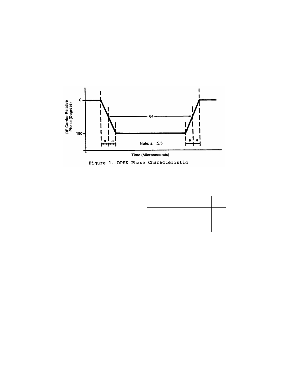
861
Federal Aviation Administration, DOT
§ 171.311
(2) CW. The CW pulse transmissions
and the CW angle transmissions as may
be required in the signal format of any
function must have characteristics
such that the requirements of para-
graph (d) of this section are met.
(d)
Radio frequency signal spectrum.
The transmitted signal must be such
that during the transmission time, the
mean power density above a height of
600 meters (2000 feet) does not exceed
¥
100.5 dBW/m
2
for angle guidance and
¥
95.5 dBW/m
2
for data, as measured in
a 150 KHz bandwidth centered at a fre-
quency of 840 KHz or more from the as-
signed frequency.
(e)
Synchronization.
Synchronization
between the azimuth and elevation
components is required and, in split-
site configurations, would normally be
accomplished by landline interconnec-
tions. Synchronization monitoring
must be provided to preclude function
overlap.
(f)
Transmission rates.
Angle guidance
and data signals must be transmitted
at the following average repetition
rates:
Function
Average
data rate
(Hertz)
Approach Azimuth .................................................
13
±
0.5
High Rate Approach Azimuth ................................
1
39
±
1.5
Approach Elevation ...............................................
39
±
1.5
Back Azimuth .........................................................
6.5
±
0.25
Basic Data .............................................................
(
2
)
Auxiliary Data ........................................................
(
3
)
1
The higher rate is recommended for azimuth scanning an-
tennas with beamwidths greater than two degrees. It should
be noted that the time available in the signal format for addi-
tional functions is limited when the higher rate is used.
2
Refer to Table 8a.
3
Refer to Table 8c.
(g)
Transmission sequences.
Sequences
of angle transmissions which will gen-
erate the required repetition rates are
shown in Figures 2 and 3.
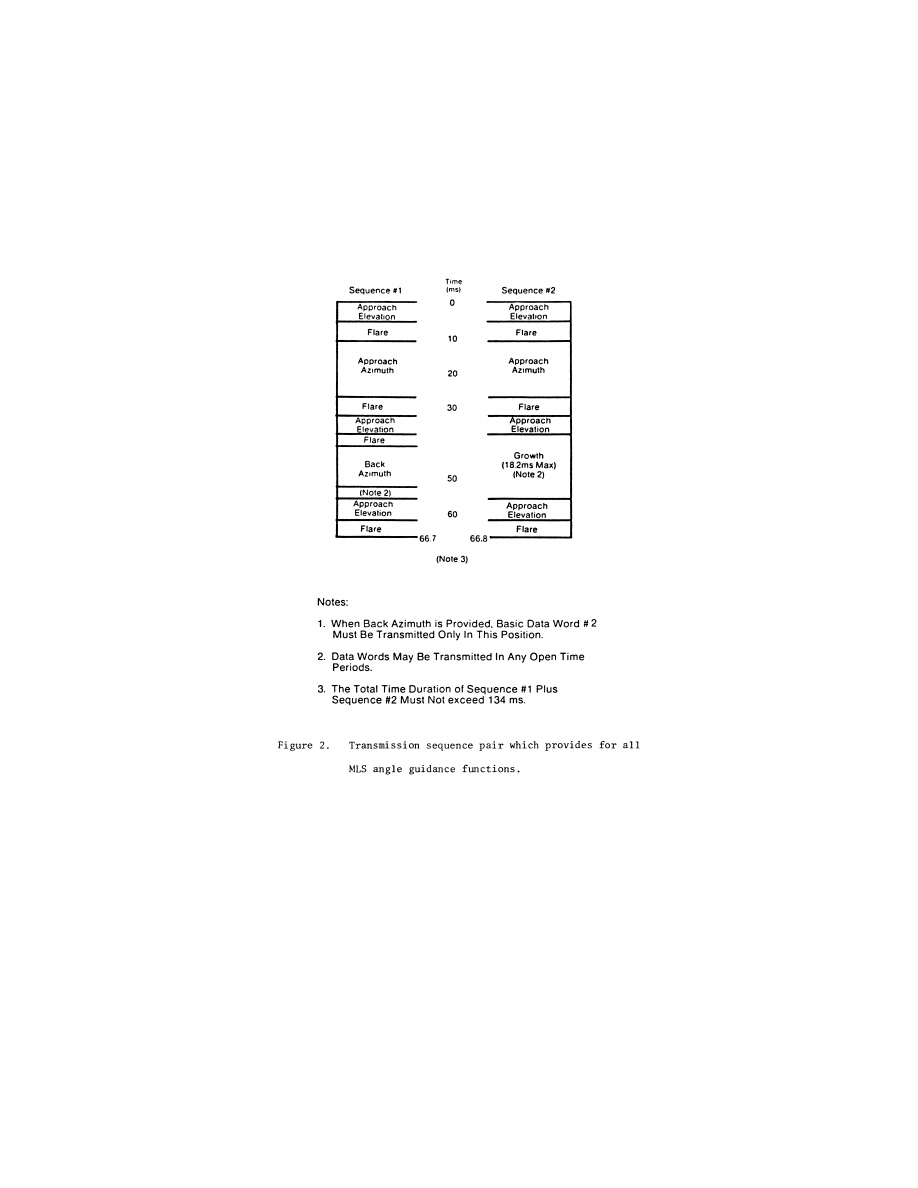
862
14 CFR Ch. I (1–1–24 Edition)
§ 171.311
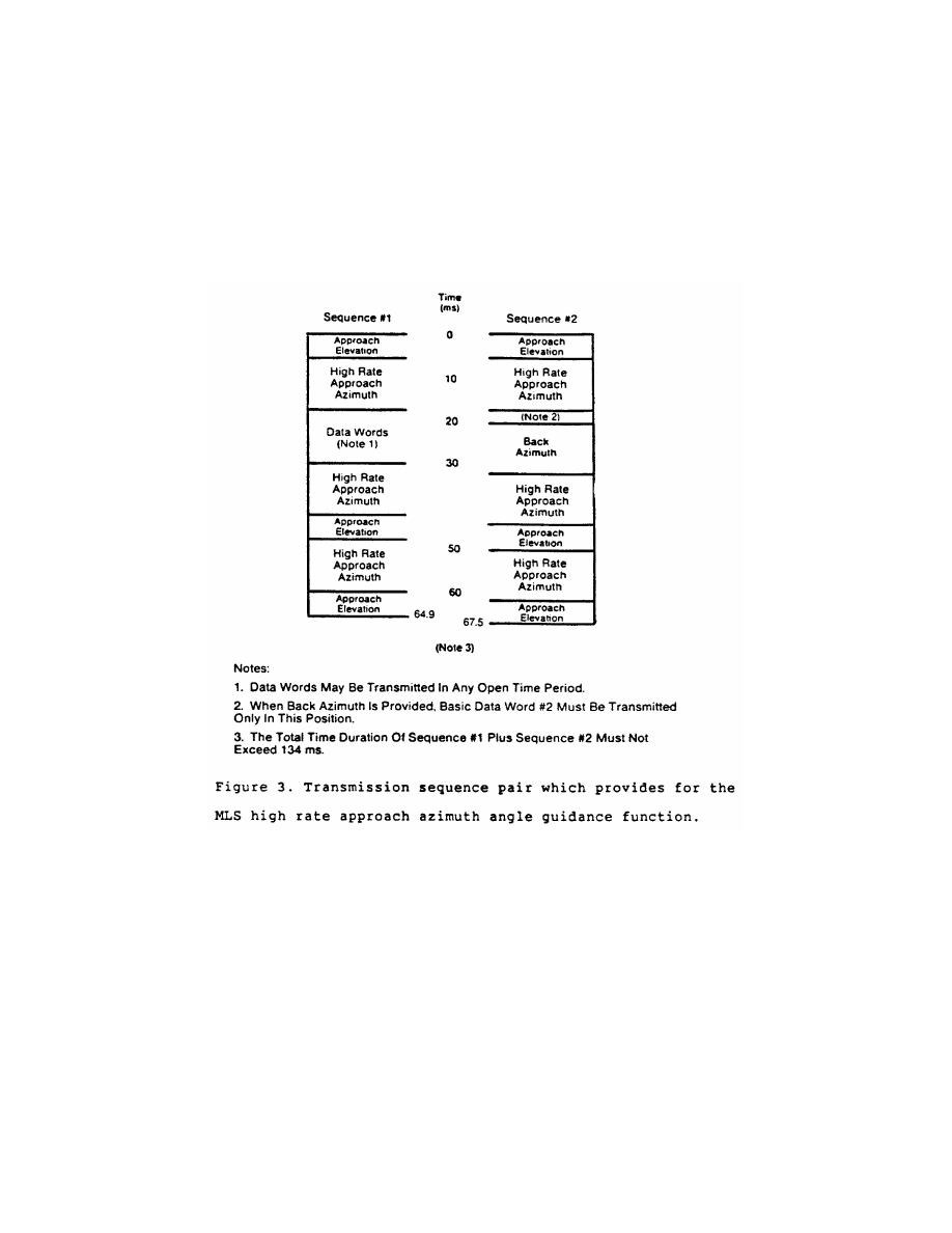
863
Federal Aviation Administration, DOT
§ 171.311
(h)
TDM cycle.
The time periods be-
tween angle transmission sequences
must be varied so that exact repeti-
tions do not occur within periods of
less than 0.5 second in order to protect
against synchronous interference. One
such combination of sequences is
shown in Figure 4 which forms a full
multiplex cycle. Data may be trans-
mitted during suitable open times
within or between the sequences.
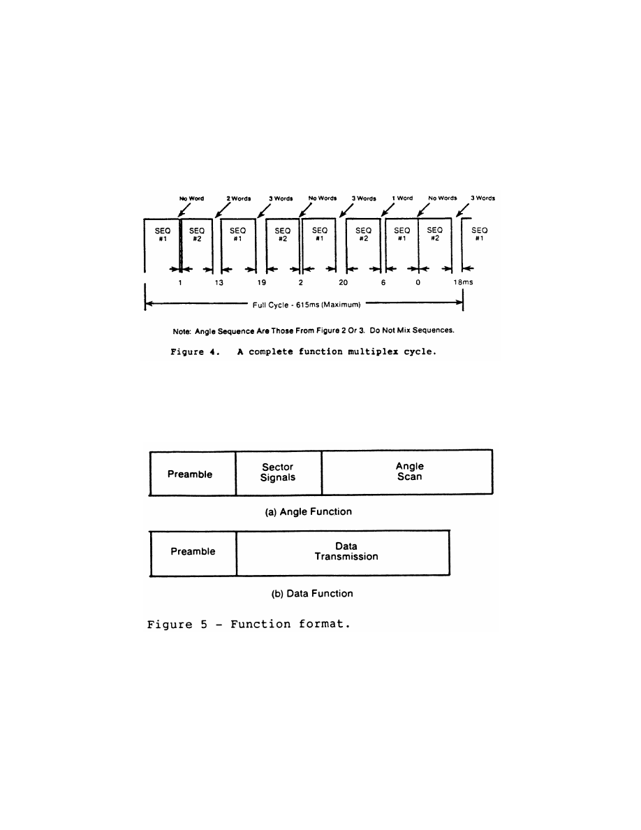
864
14 CFR Ch. I (1–1–24 Edition)
§ 171.311
(i)
Function Formats (General).
Each
angle function must contain the fol-
lowing elements: a preamble; sector
signals; and a TO and FRO angle scan
organized as shown in Figure 5a. Each
data function must contain a preamble
and a data transmission period orga-
nized as shown in Figure 5b.
(1)
Preamble format.
The transmitted
angle and date functions must use the
preamble format shown in Figure 6.
This format consists of a carrier acqui-
sition period of unmodulated CW trans-
mission followed by a receiver synchro-
nization code and a function identifica-
tion code. The preamble timing must
be in accordance with Table 2.
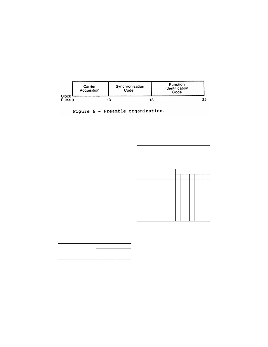
865
Federal Aviation Administration, DOT
§ 171.311
(i)
Digital codes.
The coding used in
the preamble for receiver synchroni-
zation is a Barker code logic 11101. The
time of the last phase transition mid-
point in the code shall be the receiver
reference time (see Table 2). The func-
tion identification codes must be as
shown in Table 3. The last two bits (I
11
and I
12
) of the code are parity bits
obeying the equations:
I
6
+ I
7
+ I
8
+ I
9
+ I
10
+ I
11
= Even
I
6
+ I
8
+ I
10
+ I
12
= Even
(ii)
Data modulation.
The digital code
portions of the preamble must be
DPSK modulated in accordance with
§ 171.311(c)(1) and must be transmitted
throughout the function coverage vol-
ume.
(2)
Angle function formats.
The timing
of the angle transmissions must be in
accordance with Tables 4a, 4b, and 5.
The actual timing of the TO and FRO
scans must be as required to meet the
accuracy requirements of §§ 171.313 and
171.317.
(i) Preamble. Must be in accordance
with requirements of § 171.311(i)(1).
T
ABLE
2—P
REAMBLE
T
IMING
1
Event
Event time slot begins at—
15.625 kHz
clock pulse
(number)
Time (milli-
seconds)
Carrier acquisition:
(CW transmission) ...............
0
0
Receiver reference time code:
I
1
= 1 ....................................
13
0 .832
I
2
= 1 ....................................
14
0 .896
I
3
= 1 ....................................
15
0 .960
I
4
= 0 ....................................
16
1 .024
I
5
= 1 ....................................
17
2
1 .088
Function identification:
I
6
...........................................
18
1 .152
I
7
...........................................
19
1 .216
I
8
...........................................
20
1 .280
I
9
...........................................
21
1 .344
I
10
(see table 1) ....................
22
1 .408
I
11
.........................................
23
1 .472
I
12
.........................................
24
1 .536
T
ABLE
2—P
REAMBLE
T
IMING
1
—Continued
Event
Event time slot begins at—
15.625 kHz
clock pulse
(number)
Time (milli-
seconds)
END PREAMBLE .................
25
1 .600
1
Applies to all functions transmitted.
2
Reference time for receiver synchronization for all function
timing.
T
ABLE
3—F
UNCTION
I
DENTIFICATION
C
ODES
Function
Code
I
6
I
7
I
8
I
9
I
10
I
11
I
12
Approach azimuth ....................
0
0
1
1
0
0
1
High rate approach azimuth .....
0
0
1
0
1
0
0
Approach elevation ..................
1
1
0
0
0
0
1
Back azimuth ............................
1
0
0
1
0
0
1
Basic data 1 .............................
0
1
0
1
0
0
0
Basic data 2 .............................
0
1
1
1
1
0
0
Basic data 3 .............................
1
0
1
0
0
0
0
Basic data 4 .............................
1
0
0
0
1
0
0
Basic data 5 .............................
1
1
0
1
1
0
0
Dasic data 6 .............................
0
0
0
1
1
0
1
Auxiliary data A ........................
1
1
1
0
0
1
0
Auxiliary data B ........................
1
0
1
0
1
1
1
Auxiliary data C ........................
1
1
1
1
0
0
0
(ii)
Sector signals.
In all azimuth for-
mats, sector signals must be trans-
mitted to provide Morse Code identi-
fication, airborne antenna selection,
and system test signals. These signals
are not required in the elevation for-
mats. In addition, if the signal from an
installed ground component results in
a valid indication in an area where no
valid guidance should exist, OCI signals
must be radiated as provided for in the
signal format (see Tables 4a, 4b, and 5).
The sector signals are defined as fol-
lows:
(A)
Morse Code.
DPSK transmissions
that will permit Morse Code facility
identification in the aircraft by a four
letter code starting with the letter
‘‘M’’ must be included in all azimuth
functions. They must be transmitted
and repeated at approximately equal
intervals, not less than six times per

866
14 CFR Ch. I (1–1–24 Edition)
§ 171.311
minute, during which time the ground
subsystem is available for operational
use. When the transmissions of the
ground subsystem are not available,
the identification signal must be sup-
pressed. The audible tone in the air-
craft is started by setting the Morse
Code bit to logic ‘‘1’’ and stopped by a
logic ‘‘0’’ (see Tables 4a and 4b). The
identification code characteristics
must conform to the following: the dot
must be between 0.13 and 0.16 second in
duration, and the dash between 0.39 and
0.48 second. The duration between dots
and/or dashes must be one dot plus or
minus 10%. The duration between char-
acters (letters) must not be less than
three dots. When back azimuth is pro-
vided, the code shall be transmitted by
the approach azimuth and back azi-
muth within plus or minus 0.08 seconds.
(B)
Airborne antenna selection.
A sig-
nal for airborne antenna selection shall
be transmitted as a ‘‘zero’’ DPSK sig-
nal lasting for a six-bit period (see Ta-
bles 4a and 4b).
T
ABLE
4a—A
PPROACH
A
ZIMUTH
F
UNCTION
TIMING
Event
Event time slot
begins at—
15.625
kHz clock
pulse
(number)
Time
(milli-
sec-
onds)
Preamble ...............................................
0
0
Morse code ............................................
25
1 .600
Antenna select .......................................
26
1 .664
Rear OCI ...............................................
32
2 .048
Left OCI .................................................
34
2 .176
Right OCI ...............................................
36
2 .304
To test ...................................................
38
2 .432
To scan
1
................................................
40
2 .560
Pause ....................................................
................
8 .760
Midscan point ........................................
................
9 .060
FRO scan
1
............................................
................
9 .360
FRO test ................................................
................
15 .560
End Function (Airborne) ........................
................
15 .688
End guard time; end function (ground)
................
15 .900
AA
1
The actual commencement and completion of the TO
and the FRO scan transmissions are dependent on the
amount of proportional guidance provided. The time slots pro-
vided shall accommodate a maximum scan of plus or minus
62.0 degrees. Scan timing shall be compatible with accuracy
requirements.
T
ABLE
4b—H
IGH
R
ATE
A
PPROACH
A
ZIMUTH AND
B
ACK
A
ZIMUTH
F
UNCTION
T
IMING
Event
Event time slot
begins at—
15.625
kHz clock
pulse
(number)
Time
(milli-
sec-
onds)
Preamble ...............................................
0
0
Morse Code ...........................................
25
1 .600
Antenna select .......................................
26
1 .664
Rear OCI ...............................................
32
2 .048
Left OCI .................................................
34
2 .176
Right OCI ...............................................
36
2 .304
To test ...................................................
38
2 .432
To scan
1
................................................
40
2 .560
Pause ....................................................
................
6 .760
Midscan point ........................................
................
7 .060
FRO scan
1
............................................
................
7 .360
FRO test pulse ......................................
................
11 .560
End function (airborne) ..........................
................
11 .688
End guard time; end function (ground)
................
11 .900
1
The actual commencement and completion of the TO and
the FRO scan transmissions are dependent on the amount of
proportional guidance provided. The time slots provided will
accommodate a maximum scan of plus or minus 42.0 de-
grees. Scan timing shall be compatible with accuracy
requirements.
(C)
OCI.
Where OCI pulses are used,
they must be: (1) greater than any
guidance signal in the OCI sector; (2) at
least 5 dB less than the level of the
scanning beam within the proportional
guidance sector; and (3) for azimuth
functions with clearance signals, at
least 5 dB less than the level of the left
(right) clearance pulses within the left
(right) clearance sector.
T
ABLE
5—A
PPROACH
E
LEVATION
F
UNCTION
T
IMING
Event
Event time slot
begins at:
15.625
kHz clock
pluse
(number)
Time
(milli-
sec-
onds)
Preamble ...............................................
0
0
Processor pause ....................................
25
1 .600
OCI ........................................................
27
1 .728
To scan
1
................................................
29
1 .856
Pause ....................................................
................
3 .406
Midscan point ........................................
................
3 .606
FRO scan
1
............................................
................
3 .806
End function (airborne) ..........................
................
5 .356
End guard time; end function (ground)
................
5 .600
1
The actual commencement and completion of the TO and
FRO scan transmissions are dependent upon the amount of
proportional guidance provided. The time slots provided will
accommodate a maximum scan of
¥
1.5 degrees to + 29.5
degrees. Scan timing shall be compatible with accuracy
requirements.
The duration of each pulse measured
at the half amplitude point shall be at
least 100 microseconds, and the rise and

867
Federal Aviation Administration, DOT
§ 171.311
fall times shall be less then 10 micro-
seconds. It shall be permissible to se-
quentially transmit two pulses in each
out-of-coverage indication time slot.
Where pulse pairs are used, the dura-
tion of each pulse shall be at least 50
microseconds, and the rise and fall
times shall be less then 10 microsec-
onds. The transmission of out-of-cov-
erage indication pulses radiated from
antennas with overlapping coverage
patterns shall be separated by at least
10 microseconds.
N
OTE
: If desired, two pulses may be sequen-
tially transmitted in each OCI time slot.
Where pulse pairs are used, the duration of
each pulse must be 45 (
±
5) microseconds and
the rise and fall times must be less than 10
microseconds.
(D)
System test.
Time slots are pro-
vided in Tables 4a and 4b to allow radi-
ation of TO and FRO test pulses. How-
ever, radiation of these pulses is not re-
quired since the characteristics of
these pulses have not yet been stand-
ardized.
(iii)
Angle encoding.
The encoding
must be as follows:
(A)
General.
Azimuth and elevation
angles are encoded by scanning a nar-
row beam between the limits of the
proportional coverage sector first in
one direction (the TO scan) and then in
the opposite direction (the FRO scan).
Angular information must be encoded
by the amount of time separation be-
tween the beam centers of the TO and
FRO scanning beam pulses. The TO and
FRO transmissions must be symmetri-
cally disposed about the midscan point
listed in Tables 4a, 4b, 5, and 7. The
midscan point and the center of the
time interval between the TO and FRO
scan transmissions must coincide with
a tolerance of
±
10 microseconds. Angu-
lar coding must be linear with angle
and properly decoded using the for-
mula:
θ
=
V
2
T
t
0
−
(
)
where:
q
= Receiver angle in degrees.
V = Scan velocity in degrees per micro-
second.
T
0
= Time separation in microseconds be-
tween TO and FRO beam centers cor-
responding to zero degrees.
t = Time separation in microseconds between
TO and FRO beam centers.
The timing requirements are listed in
Table 6 and illustrated in Figure 7.
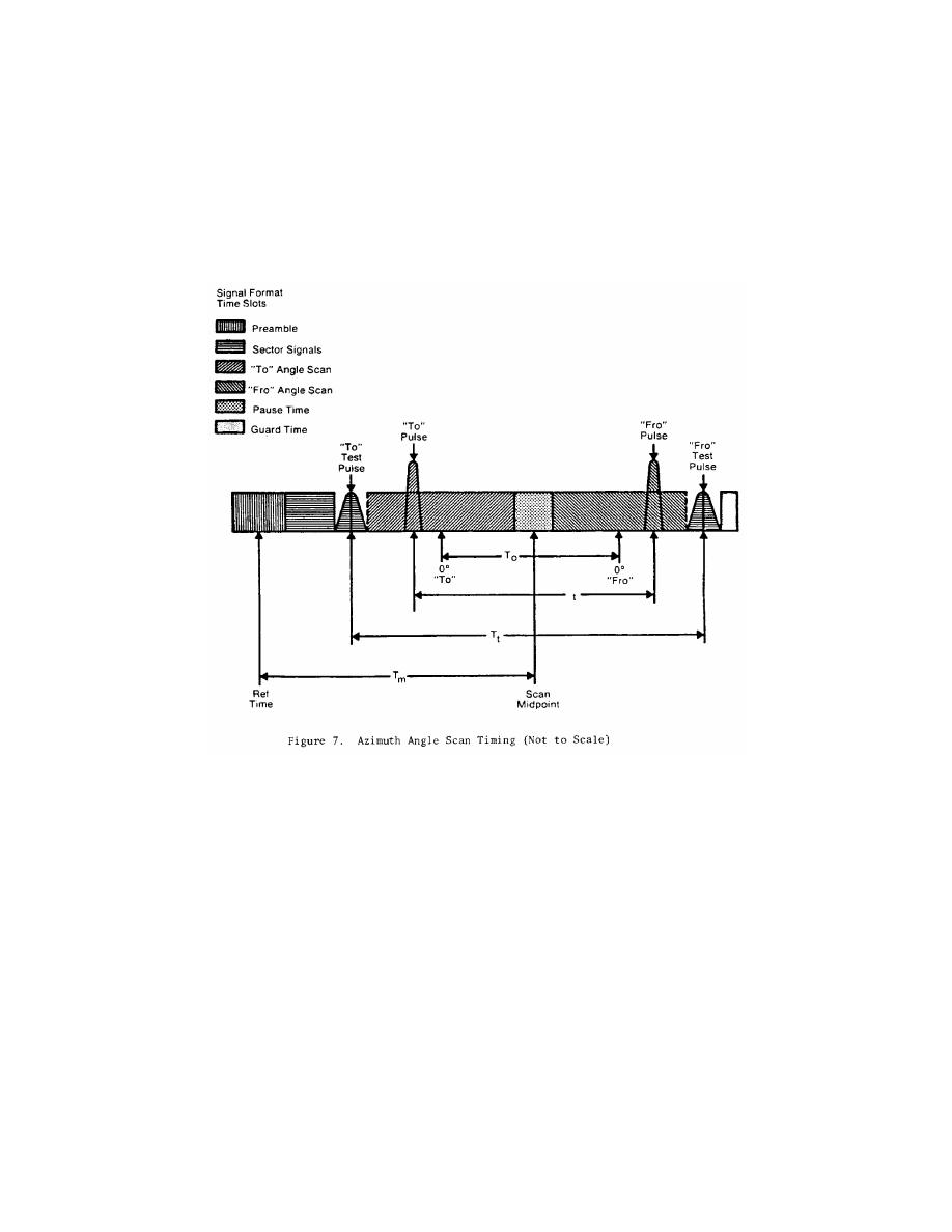
868
14 CFR Ch. I (1–1–24 Edition)
§ 171.311
(B)
Azimuth angle encoding.
Each
guidance angle transmitted must con-
sist of a clockwise TO scan followed by
a counterclockwise FRO scan as viewed
from above the antenna. For approach
azimuth functions, increasing angle
values must be in the direction of the
TO scan; for the back azimuth func-
tion, increasing angle values must be
in the direction of the FRO scan. The
antenna has a narrow beam in the
plane of the scan direction and a broad
beam in the orthogonal plane which
fills the vertical coverage.
(C)
Elevation angle encoding.
The radi-
ation from elevation equipment must
produce a beam which scans from the
horizon up to the highest elevation
angle and then scans back down to the
horizon. The antenna has a narrow
beam in the plane of the scan direction
and a broad beam in the orthogonal
plane which fills the horizontal cov-
erage. Elevation angles are defined
from the horizontal plane containing
the antenna phase center; positive an-
gles are above the horizontal and zero
angle is along the horizontal.
(iv)
Clearance guidance.
The timing of
the clearance pulses must be in accord-
ance with Figure 8. For azimuth ele-
ments with proportional coverage of
less than
±
40 degrees (
±
20 degrees for
back azimuth), clearance guidance in-
formation must be provided by trans-
mitting pulses in a TO and FRO format
adjacent to the stop/start times of the
scanning beam signal. The fly-right
clearance pulses must represent posi-
tive angles and the fly-left clearance
pulses must represent negative angles.
The duration of each clearance pulse
must be 50 microseconds with a toler-
ance of
±
5 microseconds. The trans-
mitter switching time between the
clearance pulses and the scanning

869
Federal Aviation Administration, DOT
§ 171.311
beam transmissions must not exceed 10
microseconds. The rise time at the
edge of each clearance pulse must be
less than 10 microseconds. Within the
fly-right clearance guidance section,
the fly-right clearance guidance signal
shall exceed scanning beam antenna
sidelobes and other guidance and OCI
signals by at least 5 dB; within the fly-
left clearance guidance sector, the fly
left clearance guidance signal shall ex-
ceed scanning beam antenna sidelobes
and all other guidance and OCI signals
by at least 5 dB; within the propor-
tional guidance sector, the clearance
guidance signals shall be at least 5dB
below the proportional guidance signal.
Optionally, clearance guidance may be
provided by scanning throughout the
approach guidance sector. For angles
outside the approach azimuth propor-
tional coverage limits as set in Basic
Data Word One (Basic Data Word 5 for
back azimuth), proper decode and dis-
play of clearance guidance must occur
to the limits of the guidance region.
Where used, clearance pulses shall be
transmitted adjacent to the scanning
beam signals at the edges of propor-
tional coverage as shown in Figure 8.
The proportional coverage boundary
shall be established at one beamwidth
inside the scan start/stop angles, such
that the transition between scanning
beam and clearance signals occurs out-
side the proportional coverage sector.
When clearance pulses are provided in
conjunction with a narrow beamwidth
(e.g., one degree) scanning antenna, the
scanning beam antenna shall radiate
for 15 microseconds while stationary at
the scan start/stop angles.
(3)
Data function format.
Basic data
words provide equipment characteris-
tics and certain siting information.
Basic data words must be transmitted
from an antenna located at the ap-
proach azimuth or back azimuth site
which provides coverage throughout
the appropriate sector. Data function
timing must be in accordance with
Table 7a.
T
ABLE
6—A
NGLE
S
CAN
T
IMING
C
ONSTANTS
Function
Max
value of
t
(usec)
T
o
(usec)
V(deg/
usec)
T
m
(usec)
Pause
time
(usec)
T
t
(usec)
Approach azimuth .....................................................................
13,000
6,800
0.02
7,972
600
13,128
High rate approach azimuth ......................................................
9,000
4,800
0.02
5,972
600
9,128
Approach elevation ...................................................................
3,500
3,350
0.02
2,518
400
N/A
Back azimuth .............................................................................
9,000
4,800
¥
0.02
5,972
600
9,128
T
ABLE
7a—B
ASIC
D
ATA
F
UNCTION
T
IMING
Event
Event time slot
begins at:
1
15.625
kHz clock
pulse
(number)
Time
(milli-
sec-
onds)
Preamble ...............................................
0
0
Data transmission (bits I
13
–I
30
) ..............
25
1 .600
Parity transmission (bits I
31
–I
32
) ............
43
2 .752
End function (airborne) ..........................
45
2 .880
End guard time: end function (ground)
................
3 .100
1
The previous event time slot ends at this time.
T
ABLE
7b—A
UXILIARY
D
ATA
F
UNCTION
T
IMING
—
(D
IGITAL
)
Event
Event time slot
begins at:
15.625
kHz clock
pulse
(number)
Time
(milli-
sec-
onds)
Preamble ...............................................
0
0
Address transmission (bits I
13
–I
20
) ........
25
1 .600
Data transmission: (bits I
21
–I
69
) .............
33
2 .112
T
ABLE
7b—A
UXILIARY
D
ATA
F
UNCTION
T
IMING
—
(D
IGITAL
)—Continued
Event
Event time slot
begins at:
15.625
kHz clock
pulse
(number)
Time
(milli-
sec-
onds)
Parity transmission (bits I
70
–I
76
) ............
82
5 .248
End function (airborne) ..........................
89
5 .696
End guard time; end function (ground)
................
5 .900
T
ABLE
7c—A
UXILIARY
D
ATA
F
UNCTION
T
IMING
—
(A
LPHANUMERIC
)
Event
Event time slot
begins at:
15.615
kHz clock
pulse
(number)
Time
(milli-
sec-
onds)
Preamble ...............................................
0
0
Address transmission (bits I
13
–I
20
) ........
25
1 .600
Data transmission: (bits I
21
–I
76
..............
33
2 .112
End function (airborne) ..........................
89
5 .696

870
14 CFR Ch. I (1–1–24 Edition)
§ 171.311
T
ABLE
7c—A
UXILIARY
D
ATA
F
UNCTION
T
IMING
—
(A
LPHANUMERIC
)—Continued
Event
Event time slot
begins at:
15.615
kHz clock
pulse
(number)
Time
(milli-
sec-
onds)
End guard time; (end function ground)
................
5 .900
(i)
Preamble.
Must be in accordance
with requirements of § 171.311(i)(1).
(ii)
Data transmissions.
Basic data
must be transmitted using DPSK mod-
ulation. The content and repetition
rate of each basic data word must be in
accordance with Table 8a. For data
containing digital information, binary
number 1 must represent the lower
range limit with increments in binary
steps to the upper range limit shown in
Table 8a. Data containing digital infor-
mation shall be transmitted with the
least significant bit first.
(j)
Basic Data word requirements.
Basic
Data shall consist of the items speci-
fied in Table 8a. Basic Data word con-
tents shall be defined as follows:
(1)
Approach azimuth to threshold dis-
tance
shall represent the minimum dis-
tance between the Approach Azimuth
antenna phase center and the vertical
plane perpendicular to the centerline
which contains the landing threshold.
(2)
Approach azimuth proportional cov-
erage limit
shall represent the limit of
the sector in which proportional ap-
proach azimuth guidance is trans-
mitted.
(3)
Clearance signal type
shall rep-
resent the type of clearance when used.
Pulse clearance is that which is in ac-
cordance with § 171.311 (i) (2) (iv). Scan-
ning Beam (SB) clearance indicates
that the proportional guidance sector
is limited by the proportional coverage
limits set in basic data.
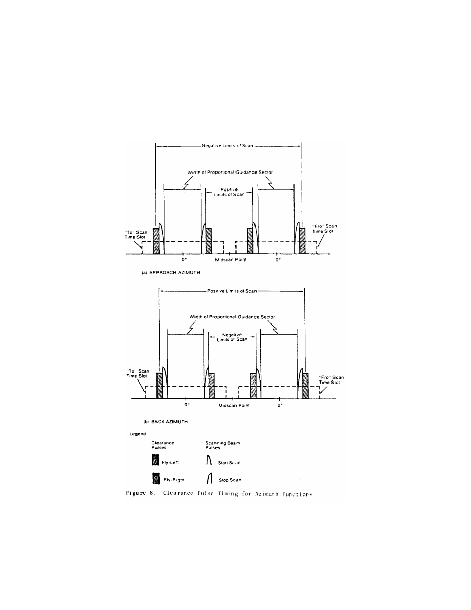
871
Federal Aviation Administration, DOT
§ 171.311
872
14 CFR Ch. I (1–1–24 Edition)
§ 171.311
T
ABLE
8a—B
ASIC
D
ATA
W
ORDS
Data bit
#
Data item definition
LSB
value
Data bit
value
Basic Data Word No. 1
1
Preamble .........................
N/A 1
2
..........................................
............
1
3
..........................................
............
1
4
..........................................
............
0
5
..........................................
............
1
6
..........................................
............
0
7
..........................................
............
1
8
..........................................
............
0
9
..........................................
............
1
10
..........................................
............
0
11
..........................................
............
0
12
..........................................
............
0
13
Approach azimuth to
threshold distance
(Om
¥
630m).
100m 100m
14
..........................................
............
200m
15
..........................................
............
400m
16
..........................................
............
800m
17
..........................................
............
1600m
18
..........................................
............
3200m
19
Approach azimuth propor-
tional coverage limit
(negative limit) (0
°
to
¥
62
°
).
2
°
¥
2
°
20
..........................................
............
¥
4
°
21
..........................................
............
¥
8
°
22
..........................................
............
¥
16
°
23
..........................................
............
¥
32
°
24
Approach azimuth propor-
tional coverage limit
(positive limit) (0
°
to +
62
°
).
2
°
2
°
25
..........................................
............
4
°
26
..........................................
............
8
°
27
..........................................
............
16
°
28
..........................................
............
32
°
29
Clearance signal type ......
N/A 0 = pulse; 1
= SB
30
Spare ...............................
............
Transmit
zero
31
Parity: (13 + 14 + 15. . .
+ 30 + 31 = odd).
N/A N/A
32
Parity: (14 + 16 + 18. . .
+ 30 + 32 = odd).
N/A N/A
Note 1: Transmit throughout the Approach Azimuth guidance
sector at intervals of 1.0 seconds or less.
Note 2: The all zero state of the data field represents the
lower limit of the absolute value of the coded parameter
unless otherwise noted.
Basic Data Word No. 2
1
Preamble .........................
N/A 1
2
..........................................
............
1
3
..........................................
............
1
4
..........................................
............
0
5
..........................................
............
1
6
..........................................
............
0
7
..........................................
............
1
8
..........................................
............
1
9
..........................................
............
1
10
..........................................
............
1
11
..........................................
............
0
12
..........................................
............
0
13
Minimum glide path (2.0
°
to 14.7
°
).
0.1
°
0.1
°
14
..........................................
............
0.2
°
15
..........................................
............
0.4
°
16
..........................................
............
0.8
°
T
ABLE
8a—B
ASIC
D
ATA
W
ORDS
—Continued
Data bit
#
Data item definition
LSB
value
Data bit
value
17
..........................................
............
1.6
°
18
..........................................
............
3.2
°
19
..........................................
............
6.4
°
20
Back azimuth status ........
............
see note 4
21
DME status ......................
............
see note 6
22
..........................................
............
23
Approach azimuth status
............
see note 4
24
Approach azimuth status
............
see note 4
25
Spare ...............................
............
Transmit
zero
26
......do ...............................
............
Do.
27
......do ...............................
............
Do.
28
......do ...............................
............
Do.
29
......do ...............................
............
Do.
30
......do ...............................
............
Do.
31
Parity: (13 + 14 + 15. . .
+ 30 + 31) = odd).
N/A N/A
32
Parity: (14 + 16 + 18. . .
+ 30 + 32 = odd).
N/A N/A
Note 1: Transmit throughout the Approach Azimuth guidance
sector at intervals of 0.16 seconds or less.
Note 2: The all zero state of the data field represents the
lower limit of the absolute range of the coded parameter
unless otherwise noted.
Basic Data Word No. 3
1
Preamble .........................
N/A 1
2
..........................................
............
1
3
..........................................
............
1
4
..........................................
............
0
5
..........................................
............
1
6
..........................................
............
1
7
..........................................
............
0
8
..........................................
............
1
9
..........................................
............
0
10
..........................................
............
0
11
..........................................
............
0
12
..........................................
............
0
13
Approach azimuth beam-
width (0.5
°
¥
4.0
°
) See
note 7.
0.5
°
0.5
°
14
..........................................
............
1.0
°
15
..........................................
............
2.0
°
16
Approach elevation
beamwidth (0.5
°
to
2.5
°
) See note 7.
0.5
°
0.5
°
17
..........................................
............
1.0
°
18
Note: values greater than
2.5
°
are invalid.
............
2.0
°
19
DME distance (Om to
6387.5m.
12.5m 12.5m
20
..........................................
............
25.0m
21
..........................................
............
50.0m
22
..........................................
............
100.0m
23
..........................................
............
200.0m
24
..........................................
............
400.0m
25
..........................................
............
800.0m
26
..........................................
............
1600.0m
27
..........................................
............
3200.0m
28
Spare ...............................
............
Transmit
zero
29
......do ...............................
............
Do.
30
......do ...............................
............
Do.
31
Parity: (13 + 14 + 15. . .
+ 30 + 31 = odd).
............
32
Parity: (14 + 16 + 18. . .
+ 30 + 32 = odd).
N/A N/A

873
Federal Aviation Administration, DOT
§ 171.311
T
ABLE
8a—B
ASIC
D
ATA
W
ORDS
—Continued
Data bit
#
Data item definition
LSB
value
Data bit
value
Note 1: Transmit throughout the Approach Azimuth guidance
sector at intervals of 1.0 seconds or less.
Note 2: The all zero state of the data field represents the
lower limit of the absolute range of the coded parameter
unless otherwise noted.
Basic Data Word No. 4
1
Preamble .........................
N/A 1
2
..........................................
............
1
3
..........................................
............
1
4
..........................................
............
0
5
..........................................
............
1
6
..........................................
............
1
7
..........................................
............
0
8
..........................................
............
0
9
..........................................
............
0
10
..........................................
............
1
11
..........................................
............
0
12
..........................................
............
0
13
Approach azimuth mag-
netic orientation (0
°
to
359
°
).
1
°
1
°
14
..........................................
............
2
°
15
..........................................
............
4
°
16
..........................................
............
8
°
17
..........................................
............
16
°
18
..........................................
............
32
°
19
..........................................
............
64
°
20
..........................................
............
128
°
21
..........................................
............
256
°
22
Back azimuth magnetic
orientation (0
°
to 359
°
).
1
°
1
°
23
..........................................
............
2
°
24
..........................................
............
4
°
25
..........................................
............
8
°
26
..........................................
............
16
°
27
..........................................
............
32
°
28
..........................................
............
64
°
29
..........................................
............
128
°
30
..........................................
............
256
°
31
Parity: (13 + 14 + 15. . .
+ 30 + 31 = odd).
N/A N/A
32
Parity: (14 + 16 + 18. . .
+ 30 + 32 = odd).
N/A N/A
Note 1: Transmit at intervals of 1.0 second or less through-
out the Approach Azimuth guidance sector, except when
Back Azimuth guidance is provided. See Note 8.
Note 2: The all zero state of the data field represents the
lower limit of the absolute range of the coded parameter
unless otherwise noted.
Basic Data Word No. 5
1
Preamble .........................
N/A 1
2
..........................................
............
1
3
..........................................
............
1
4
..........................................
............
0
5
..........................................
............
1
6
..........................................
............
1
7
..........................................
............
1
8
..........................................
............
0
9
..........................................
............
1
10
..........................................
............
1
11
..........................................
............
0
12
..........................................
............
0
13
Back azimuth proportional
coverage negative limit
(0
°
to
¥
42
°
).
2
°
¥
2
°
14
..........................................
............
¥
4
°
15
..........................................
............
¥
8
°
T
ABLE
8a—B
ASIC
D
ATA
W
ORDS
—Continued
Data bit
#
Data item definition
LSB
value
Data bit
value
16
..........................................
............
¥
16
°
17
..........................................
............
¥
32
°
18
Back azimuth proportional
coverage positive limit
(0
°
to + 42
°
).
2
°
2
°
19
..........................................
............
4
°
20
..........................................
............
8
°
21
..........................................
............
16
°
22
..........................................
............
32
°
23
Back azimuth beamwidth
(0.5
°
to 4.0
°
) See note
7.
0.5
°
0.5
°
24
..........................................
............
1.0
°
25
..........................................
............
2.0
°
26
Back azimuth status ........
............
See Note 10
27
......do ...............................
............
Do.
28
......do ...............................
............
Do.
29
......do ...............................
............
Do.
30
......do ...............................
............
Do.
31
Parity: (13 + 14 + 15. . .
+ 30 + 31 = odd).
N/A N/A
32
Parity: (14 + 16 + 18. . .
+ 30 + 32 = odd).
N/A N/A
Note 1: Transmit only when Back Azimuth guidance is pro-
vided. See note 9.
Note 2: The all zero state of the data filed represents the
lower limit of the absolute range of the coded parameter
unless otherwise noted.
Basic Data Word No. 6
1
Preamble .........................
N/A 1
2
..........................................
............
1
3
..........................................
............
1
4
..........................................
............
0
5
..........................................
............
1
6
..........................................
............
0
7
..........................................
............
0
8
..........................................
............
0
9
..........................................
............
1
10
..........................................
............
1
11
..........................................
............
0
12
..........................................
............
1
(13–
30)
MLS ground equipment
identification (Note 3).
............
13
Character 2 ......................
N/A B1
14
..........................................
............
B2
15
..........................................
............
B3
16
..........................................
............
B4
17
..........................................
............
B5
18
..........................................
............
B6
19
Character 3 ......................
N/A B1
20
..........................................
............
B2
21
..........................................
............
B3
22
..........................................
............
B4
23
..........................................
............
B5
24
..........................................
............
B6
25
Character 4 ......................
N/A B1
26
..........................................
............
B2
27
..........................................
............
B3
28
..........................................
............
B4
29
..........................................
............
B5
30
..........................................
............
B6
31
Parity: (13 + 14 + 15. . .
+ 30 + 31 = odd).
N/A N/A
32
Parity: (14 + 16 + 18. . .
+ 30 + 32 = odd).
N/A N/A
Note 1: Transmit at intervals of 1.0 second or less through-
out the Approach Azimuth guidance sector, except when Back
Azimuth guidance is provided. See note 8.

874
14 CFR Ch. I (1–1–24 Edition)
§ 171.311
Note 3: Characters are encoded using the International Al-
phabet Number 5, (IA–5):
Note 4: Coding for status bit:
0 = Function not radiated, or radiated in test mode (not reli-
able for navigation).
1 = Function radiated in normal mode (for Back Azimuth,
this also indicates that a Back Azimuth transmission follows).
Note 5: Date items which are not applicable to a particular
ground equipment shall be transmitted as all zeros.
Note 6: Coding for status bits:
I
21
I
22
0
0 DME transponder inoperative or not available.
1
0 Only IA mode or DME/N available.
0
0 FA mode, Standard 1, available.
1
1 FA mode, Standard 2, available.
Note 7: The value coded shall be the actual beamwidth (as
defined in § 171.311 (j)(9) rounded to the nearest 0.5 degree.
Note 8: When back Azimuth guidance is provided, Data
Words 4 and 6 shall be transmitted at intervals of 1.33 sec-
onds or less throughout the Approach Azimuth coverage and
4 seconds or less throughout the Back Azimuth coverage.
Note 9: When Back Azimuth guidance is provided, Data
Word 5 shall be transmitted at an interval of 1.33 seconds or
less throughout the Back Azimuth coverage sector and 4 sec-
onds or less throughout the Approach Azimuth coverage sec-
tor.
Note 10: Coding for status bit:
0 = Function not radiated, or radiated in test mode (not reli-
able for navigation).
1 = Function radiated in normal mode.
(4)
Minimum glidepath
the lowest
angle of descent along the zero degree
azimuth that is consistent with pub-
lished approach procedures and obsta-
cle clearance criteria.
(5)
Back azimuth status
shall represent
the operational status of the Back Azi-
muth equipment.
(6)
DME status
shall represent the
operational status of the DME equip-
ment.
(7)
Approach azimuth status
shall rep-
resent the operational status of the ap-
proach azimuth equipment.
(8)
Approach elevation status
shall rep-
resent the operational status of the ap-
proach elevation equipment.
(9)
Beamwidth
the width of the scan-
ning beam main lobe measured at the
¥
3 dB points and defined in angular
units on the antenna boresight, in the
horizontal plane for the azimuth func-
tion and in the vertical plane for the
elevation function.
(10)
DME distance
shall represent the
minimum distance between the DME
antenna phase center and the vertical
plane perpendicular to the runway cen-
terline which contains the MLS datum
point.
(11)
Approach azimuth magnetic ori-
entation
shall represent the angle meas-
ured in the horizontal plane clockwise
from Magnetic North to the zero-de-
gree angle guidance radial originating
from the approach azimuth antenna
phase center. The vertex of the meas-
ured angle shall be at the approach azi-
muth antenna phase center.
N
OTE
: For example, this data item would
be encoded 090 for an approach azimuth an-
tenna serving runway 27 (assuming the mag-
netic heading is 270 degrees) when sited such
that the zero degree radial is parallel to cen-
terline.
(12)
Back azimuth magnetic orientation
shall represent the angle measured in
the horizontal plane clockwise from
Magnetic North to the zero-degree
angle guidance radial originating from
the Back Azimuth antenna. The vertex
of the measured angle shall be at the
Back Azimuth antenna phase center.
N
OTE
: For example, this data item would
be encoded 270 for a Back Azimuth Antenna
serving runway 27 (assuming the magnetic
heading is 270 degrees) when sited such that
the zero degree radial is parallel to center-
line.
(13)
Back azimuth proportional cov-
erage limit
shall represent the limit of
the sector in which proportional back
azimuth guidance is transmitted.
(14)
MLS ground equipment identifica-
tion
shall represent the last three char-
acters of the system identification
specified in § 171.311(i)(2). The char-
acters shall be encoded in accordance
with International Alphabet No. 5 (IA–
5) using bits b
1
through b
6
.
N
OTE
: Bit b
7
of this code may be recon-
structed in the airborne receiver by taking
the complement of bit b
6
.
(k)
Residual radiation.
The residual
radiation of a transmitter associated
with an MLS function during time in-
tervals when it should not be transmit-
ting shall not adversely affect the re-
ception of any other function. The re-
sidual radiation of an MLS function at
times when another function is radi-
ating shall be at least 70 dB below the
level provided when transmitting.
(l)
Symmetrical scanning.
The TO and
FRO scan transmissions shall be sym-
metrically disposed about the mid-scan
point listed in Tables 4a, 4b and 5. The
mid-scan point and the center of the
time interval between the TO and FRO
scan shall coincide with a tolerance of
plus or minus 10 microseconds.
(m)
Auxiliary data
—(1)
Addresses.
Three function identification codes are
reserved to indicate transmission of
Auxiliary Data A, Auxiliary Data B,

875
Federal Aviation Administration, DOT
§ 171.313
and Auxiliary Data C. Auxiliary Data
A contents are specified below, Auxil-
iary Data B contents are reserved for
future use, and Auxiliary Data C con-
tents are reserved for national use. The
address codes of the auxiliary data
words shall be as shown in Table 8b.
(2)
Organization and timing.
The orga-
nization and timing of digital auxiliary
data must be as specified in Table 7b.
Data containing digital information
must be transmitted with the least sig-
nificant bit first. Alphanumeric data
characters must be encoded in accord-
ance with the 7-unit code character set
as defined by the American National
Standard Code for Information Inter-
change (ASCII). An even parity bit is
added to each character. Alphanumeric
data must be transmitted in the order
in which they are to be read. The serial
transmission of a character must be
with the lower order bit transmitted
first and the parity bit transmitted
last. The timing for alphanumeric aux-
iliary data must be as shown in Table
7c.
(3)
Auxiliary Data A content:
The data
items specified in Table 8c are defined
as follows:
(i)
Approach azimuth antenna offset
shall represent the minimum distance
between the Approach Azimuth an-
tenna phase center and the vertical
plane containing the runway center-
line.
(ii)
Approach azimuth to MLS datum
point distance
shall represent the min-
imum distance between the Approach
Azimuth antenna phase center and the
vertical plane perpendicular to the cen-
terline which contains the MLS datum
point.
(iii)
Approach azimuth alignment with
runway centerline
shall represent the
minimum angle between the approach
azimuth antenna zero-degree guidance
plane and the runway certerline.
(iv)
Approach azimuth antenna coordi-
nate system
shall represent the coordi-
nate system (planar or conical) of the
angle data transmitted by the ap-
proach azimuth antenna.
(v)
Approach elevation antenna offset
shall represent the minimum distance
between the elevation antenna phase
center and the vertical plane con-
taining the runway centerline.
(vi)
MLS datum point to threshold dis-
tance
shall represent the distance
measured along the runway centerline
from the MLS datum point to the run-
way threshold.
(vii)
Approach elevation antenna
height
shall represent the height of the
elevation antenna phase center rel-
ative to the height of the MLS datum
point.
(viii)
DME offset
shall represent the
minimum distance between the DME
antenna phase center and the vertical
plane containing the runway center-
line.
(ix)
DME to MLS datum point distance
shall represent the minimum distance
between the DME antenna phase center
and the vertical plane perpendicular to
the centerline which contains the MLS
datum point.
(x)
Back azimuth antenna offset
shall
represent the minimum distance be-
tween the back azimuth antenna phase
center and the vertical plane con-
taining the runway centerline.
(xi)
Back azimuth to MLS datum point
distance
shall represent the minimum
distance between the Back Azimuth
antenna and the vertical plane perpen-
dicular to the centerline which con-
tains the MLS datum point.
(xii)
Back azimuth antenna alignment
with runway centerline
shall represent
the minimum angle between the back
azimuth antenna zero-degree guidance
plane and the runway centerline.
§ 171.313 Azimuth performance re-
quirements.
This section prescribes the perform-
ance requirements for the azimuth
equipment of the MLS as follows:
(a)
Approach azimuth coverage require-
ments.
The approach azimuth equip-
ment must provide guidance informa-
tion in at least the following volume of
space (see Figure 9):
T
ABLE
8b—A
UXILIARY
D
ATA
W
ORD
A
DDRESS
C
ODES
No.
I
13
I
14
I
15
I
16
I
17
I
18
I
19
I
20
1.
0
0
0
0
0
1
1
1
2.
0
0
0
0
1
0
1
0
3.
0
0
0
0
1
1
0
1
4.
0
0
0
1
0
0
1
1
5.
0
0
0
1
0
1
0
0
6.
0
0
0
1
1
0
0
1
7.
0
0
0
1
1
1
1
0
8.
0
0
1
0
0
0
1
0
876
14 CFR Ch. I (1–1–24 Edition)
§ 171.313
T
ABLE
8b—A
UXILIARY
D
ATA
W
ORD
A
DDRESS
C
ODES
—Continued
No.
I
13
I
14
I
15
I
16
I
17
I
18
I
19
I
20
9.
0
0
1
0
0
1
0
1
10.
0
0
1
0
1
0
0
0
11.
0
0
1
0
1
1
1
1
12.
0
0
1
1
0
0
0
1
13.
0
0
1
1
0
1
1
0
14.
0
0
1
1
1
0
1
1
15.
0
0
1
1
1
1
0
0
16.
0
1
0
0
0
0
1
1
17.
0
1
0
0
0
1
0
0
18.
0
1
0
0
1
0
0
1
19.
0
1
0
0
1
1
1
0
20.
0
1
0
1
0
0
0
0
21.
0
1
0
1
0
1
1
1
22.
0
1
0
1
1
0
1
0
23.
0
1
0
1
1
1
0
1
24.
0
1
1
0
0
0
0
1
25.
0
1
1
0
0
1
1
0
26.
0
1
1
0
1
0
1
1
27.
0
1
1
0
1
1
0
0
28.
0
1
1
1
0
0
1
0
29.
0
1
1
1
0
1
0
1
30.
0
1
1
1
1
0
0
0
31.
0
1
1
1
1
1
1
1
32.
1
0
0
0
0
0
1
0
33.
1
0
0
0
0
1
0
1
34.
1
0
0
0
1
0
0
0
35.
1
0
0
0
1
1
1
1
36.
1
0
0
1
0
0
0
1
37.
1
0
0
1
0
1
1
0
38.
1
0
0
1
1
0
1
1
39.
1
0
0
1
1
1
0
0
40.
1
0
1
0
0
0
0
0
T
ABLE
8b—A
UXILIARY
D
ATA
W
ORD
A
DDRESS
C
ODES
—Continued
No.
I
13
I
14
I
15
I
16
I
17
I
18
I
19
I
20
41.
1
0
1
0
0
1
1
1
42.
1
0
1
0
1
0
1
0
43.
1
0
1
0
1
1
0
1
44.
1
0
1
1
0
0
1
1
45.
1
0
1
1
0
1
0
0
46.
1
0
1
1
1
0
0
1
47.
1
0
1
1
1
1
1
0
48.
1
1
0
0
0
0
0
1
49.
1
1
0
0
0
1
1
0
50.
1
1
0
0
1
0
1
1
51.
1
1
0
0
1
1
0
0
52.
1
1
0
1
0
0
1
0
53.
1
1
0
1
0
1
0
1
54.
1
1
0
1
1
0
0
0
55.
1
1
0
1
1
1
1
1
56.
1
1
1
0
0
0
1
1
57.
1
1
1
0
0
1
0
0
58.
1
1
1
0
1
0
0
1
59.
1
1
1
0
1
1
1
0
60.
1
1
1
1
0
0
0
0
61.
1
1
1
1
0
1
1
1
62.
1
1
1
1
1
0
1
0
63.
1
1
1
1
1
1
0
1
64.
0
0
0
0
0
0
0
0
N
OTE
1: Parity bits I
19
and I
20
are chosen to
satisfy the equations:
I
13
+ I
14
+ I
15
+ I
16
+ I
17
+ I
18
+ I
19
= EVEN
I
14
+ I
16
+ I
18
+ I
20
= EVEN
T
ABLE
8
C
—A
UXILIARY
D
ATA
Word
(See
note 6)
Data content
Type
of data
Maximun
time be-
tween trans-
missions
(Seconds)
Bits
used
Range of values
Least
sig-
nifi-
cant
bit
A1 ......
Preamble .....................................................
Digital
1.0
12 ......................................................
.........
Address ........................................................
...........
....................
8 ......................................................
.........
Approach azimuth antenna offset ...............
...........
....................
10
¥
511 m to + 511 m (See note 3)
1 m
Approach azimuth to MLS datum point dis-
tance.
...........
....................
13 0 m to 8 191 m ............................
1 m
Approach azimuth antenna alignment with
runway centerline.
...........
....................
12
¥
20.47
°
to 20.47
°
(See note 3) ..
0.01
°
Approach azimuth antenna coordinate sys-
tem.
...........
....................
1 (See note 2) .................................
.........
Spare ...........................................................
...........
....................
13 ......................................................
.........
Parity ............................................................
...........
....................
7 (See note 1) .................................
.........
A2 ......
Preamble .....................................................
Digital
1.0
12 ......................................................
.........
Address ........................................................
...........
....................
8 ......................................................
.........
Approach elevation antenna offset ..............
...........
....................
10
¥
511 m to + 511 m (See note 3)
1 m
MLS datum point to threshold distance ......
...........
....................
10 0 m to 1 023 m ............................
1 m
Approach elevation antenna height .............
...........
....................
7
¥
6.3 m to + 6.3 m (See note 3)
0.1
m
Spare ...........................................................
...........
....................
22 ......................................................
.........
Parity ............................................................
...........
....................
7 (See note 1) .................................
.........
A3 ......
Preamble .....................................................
Digital
(See note 4)
12 ......................................................
.........
Address ........................................................
...........
....................
8 ......................................................
.........
DME offset ...................................................
...........
....................
10
¥
511 m to + 511 m ....................
1 m
DME to MLS datum point distance .............
...........
....................
14
¥
8 191 m to + 8 191 m (See
note 3).
1 m
Spare ...........................................................
...........
....................
25 ......................................................
.........
Parity ............................................................
...........
....................
7 (See note 1) .................................
.........
A4 ......
Preamble .....................................................
Digital
(See note 5)
12 ......................................................
.........
Address ........................................................
...........
....................
8 ......................................................
.........
Back azimuth antenna .................................
...........
....................
10
¥
511 m to + 511 m (See note 3)
1 m
Back azimuth to MLS datum point distance
...........
....................
11 0 m to 2 047 m ............................
1 m

877
Federal Aviation Administration, DOT
§ 171.313
T
ABLE
8
C
—A
UXILIARY
D
ATA
—Continued
Word
(See
note 6)
Data content
Type
of data
Maximun
time be-
tween trans-
missions
(Seconds)
Bits
used
Range of values
Least
sig-
nifi-
cant
bit
Back azimuth antenna alignment with run-
way centerline.
...........
....................
12
¥
20.47
°
to 20.47
°
(See note 3) ..
0.01
°
Spare ...........................................................
...........
....................
16 ......................................................
.........
Parity ............................................................
...........
....................
7 (See note 1) .................................
.........
N
OTE
1: Parity bits I
70
to I
76
are chosen to
satisfy the equations which follow:
For BIT I
70
:
Even = (I
13
+ ... + I
18
) + I
20
+ I
22
+ I
24
+ I
25
+ I
28
+ I
29
+ I
31
+ I
32
+ I
33
+ I
35
+ I
36
+ I
38
+ I
41
+ I
44
+ I
45
+ I
46
+ I
50
+ (I
52
+ ... + I
55
) + I
58
+
I
60
+ I
64
+ I
65
+ I
70
For BIT I
71
:
Even = (I
14
+ ... + I
19
) + I
21
+ I
23
+ I
25
+ I
26
+ I
29
+ I
30
+ I
32
+ I
33
+ I
34
+ I
36
+ I
37
+ I
39
+ I
42
+ I
45
+ I
46
+ I
47
+ I
51
+ (I
53
+ ... + I
56
) + I
59
+
I
61
+ I
65
+ I
66
+ I
71
For BIT I
72
:
Even = (I
15
+ ... + I
20
) + I
22
+ I
24
+ I
26
+ I
27
+ I
30
+ I
31
+ I
33
+ I
34
+ I
35
+ I
37
+ I
38
+ I
40
+ I
43
+ I
46
+ I
47
+ I
48
+ I
52
+ (I
54
+ ... + I
57
) + I
60
+
I
62
+ I
66
+ I
67
+ I
72
For BIT I
73
:
Even = (I
16
+ ... + I
21
) + I
23
+ I
25
+ I
27
+ I
28
+ I
31
+ I
32
+ I
34
+ I
35
+ I
36
+ I
38
+ I
39
+ I
41
+ I
44
+ I
47
+ I
48
+ I
49
+ I
53
+ (I
55
+ ... + I
58
) + I
61
+
I
63
+ I
67
+ I
68
+ I
73
For BIT I
74
:
Even = (I
17
+ ... + I
22
) + I
24
+ I
26
+ I
28
+ I
29
+ I
32
+ I
33
+ I
35
+ I
36
+ I
37
+ I
39
+ I
40
+ I
42
+ I
45
+ I
48
+ I
49
+ I
50
+ I
54
+ (I
56
+ ... + I
59
) + I
62
+
I
64
+ I
68
+ I
69
+ I
74
For BIT I
75
:
Even = (I
13
+ ... + I
17
) + I
19
+ I
21
+ I
23
+ I
24
+ I
27
+ I
28
+ I
30
+ I
31
+ I
32
+ I
34
+ I
35
+ I
37
+ I
40
+ I
43
+ I
44
+ I
45
+ I
49
+ (I
51
+ ... + I
54
) + I
57
+
I
59
+ I
63
+ I
64
+ I
69
+ I
75
For BIT I
76
:
Even = I
13
+ I
14
+ ... + I
75
+ I
76
N
OTE
2: Code for I
56
is: 0 = conical; 1 =
planar.
N
OTE
3: The convention for the coding of
negative numbers is as follows:
¥
MSB is the
sign bit; 0 = + ; 1 =
¥
.
—Other bits represent the absolute value.
The convention for the antenna location is
as follows: As viewed from the MLS approach
reference datum looking toward the datum
point, a positive number shall represent a lo-
cation to the right of the runway centerline
(lateral offset) or above the runway (vertical
offset), or towards the stop end of the run-
way (longitudinal distance).
The convention for the antenna alignment
is as follows: As viewed from above, a posi-
tive number shall represent clockwise rota-
tion from the runway centerline to the re-
spective zero-degree guidance plane.
N
OTE
4: Data Word A3 is transmitted at in-
tervals of 1.0 seconds or less throughout the
approach Azimuth coverage sector, except
when back Azimuth guidance is provided.
Where back Azimuth is provided transmit at
intervals of 1.33 seconds or less throughout
the approach Azimuth sector and 4.0 seconds
or less throughout the back Azimuth cov-
erage sector.
N
OTE
5: When back Azimuth guidance is
provided, transmit at intervals of 1.33 sec-
onds or less throughout the back Azimuth
coverage sector and 4.0 seconds or less
throughout the approach Azimuth coverage
sector.
N
OTE
6: The designation ‘‘A1’’ represents
the function identification code for ‘‘Auxil-
iary Data A’’ and address code number 1.
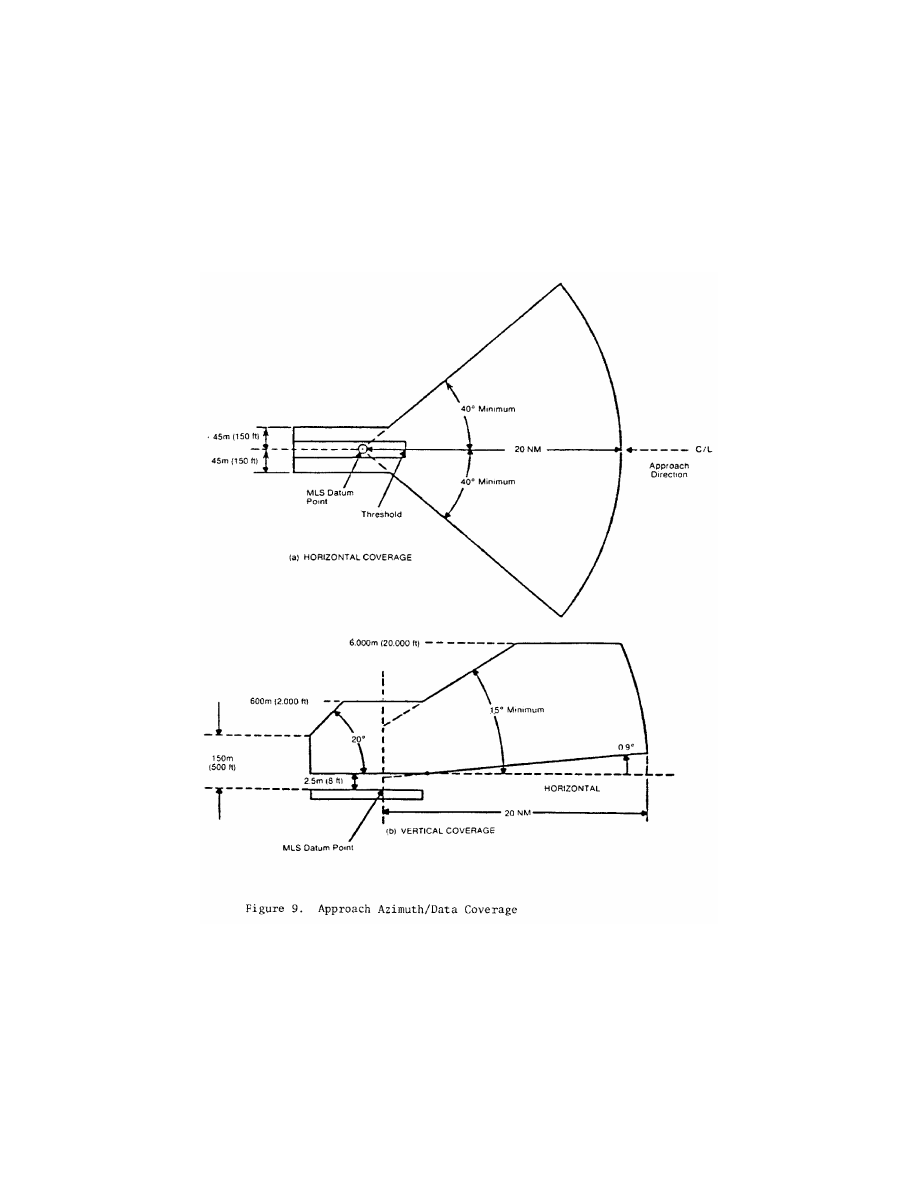
878
14 CFR Ch. I (1–1–24 Edition)
§ 171.313
(1) Horizontally within a sector plus
or minus 40 degrees about the runway
centerline originating at the datum
point and extending in the direction of
the approach to 20 nautical miles from
the runway threshold. The minimum
proportional guidance sector must be
plus or minus 10 degrees about the run-
way centerline. Clearance signals must
be used to provide the balance of the
required coverage, where the propor-
tional sector is less than plus or minus
40 degrees. When intervening obstacles
prevent full coverage, the
±
40
°
guidance
sector can be reduced as required. For
systems providing
±
60
°
lateral guidance

879
Federal Aviation Administration, DOT
§ 171.313
the coverage requirement is reduced to
14 nm beyond
±
40
°
.
(2) Vertically between:
(i) A conical surface originating 2.5
meters (8 feet) above the runway cen-
terline at threshold inclined at 0.9 de-
gree above the horizontal.
(ii) A conical surface originating at
the azimuth ground equipment antenna
inclined at 15 degrees above the hori-
zontal to a height of 6,000 meters (20,000
feet).
(iii) Where intervening obstacles pen-
etrate the lower surface, coverage need
be provided only to the minimum line
of sight.
(3) Runway region:
(i) Proportional guidance hori-
zontally within a sector 45 meters (150
feet) each side of the runway centerline
beginning at the stop end and extend-
ing parallel with the runway centerline
in the direction of the approach to join
the approach region. This requirement
does not apply to offset azimuth instal-
lations.
(ii) Vertically between a horizontal
surface which is 2.5 meters (8 feet)
above the farthest point of runway cen-
terline which is in line of sight of the
azimuth antenna, and in a conical sur-
face originating at the azimuth ground
equipment antenna inclined at 20 de-
grees above the horizontal up to a
height to 600 meters (2,000 feet). This
requirement does not apply to offset
azimuth installations.
(4) Within the approach azimuth cov-
erage sector defined in paragraphs (a)
(1), and (2) and (3) of this section, the
power densities must not be less than
those shown in Table 9 but the equip-
ment design must also allow for:
(i) Transmitter power degradation
from normal by
¥
1.5 dB;
T
ABLE
9—M
INIMUM
P
OWER
D
ENSITY
W
ITHIN
C
OVERAGE
B
OUNDARIES
(
D
BW/
M
2
)
Function
Data
signals
Angle signals for various antenna
beamwidths
Clearance
signals
1
°
1.5
°
2
°
3
°
Approach azimuth .......................................................................
¥
89.5
¥
88 ..........
¥
85.5
¥
82
¥
88
High rate approach azimuth ........................................................
¥
89.5
¥
88 ..........
¥
88
¥
86.5
¥
88
Back azimuth ...............................................................................
¥
89.5
¥
88 ..........
¥
85.5
¥
82
¥
88
Approach elevation .....................................................................
¥
89.5
¥
88
¥
88
¥
88 ..............
....................
(ii) Rain loss of
¥
2.2 dB at the longi-
tudinal coverage extremes.
(b)
Siting requirements.
The approach
azimuth antenna system must, except
as allowed in paragraph (c) of this sec-
tion:
(1) Be located on the extension of the
centerline of the runway beyond the
stop end;
(2) Be adjusted so that the zero de-
gree azimuth plane will be a vertical
plane which contains the centerline of
the runway served;
(3) Have the minimum height nec-
essary to comply with the coverage re-
quirements prescribed in paragraph (a)
of this section;
(4) Be located at a distance from the
stop end of the runway that is con-
sistent with safe obstruction clearance
practices;
(5) Not obscure any light of an ap-
proach lighting system; and
(6) Be installed on frangible mounts
or beyond the 300 meter (1,000 feet)
light bar.
(c) On runways where limited terrain
prevents the azimuth antenna from
being positioned on the runway center-
line extended, and the cost of the land
fill or a tall tower antenna support is
prohibitive, the azimuth antenna may
be offset.
(d)
Antenna coordinates.
The scanning
beams transmitted by the approach
azimuth equipment within
±
40
°
of the
centerline may be either conical or
planar.
(e)
Approach azimuth accuracy.
(1) The
system and subsystem errors shall not
exceed those listed in Table 10 at the
approach reference datum.
At the approach reference datum,
temporal sinusoidal noise components
shall not exceed 0.025 degree peak in
the frequency band 0.01 Hz to 1.6 Hz,
and the CMN shall not exceed 0.10 de-
gree. From the approach reference

880
14 CFR Ch. I (1–1–24 Edition)
§ 171.313
datum to the coverage limit, the PFE,
PFN and CMN limits, expressed in an-
gular terms, shall be allowed to lin-
early increase as follows:
(i) With distance along the runway
centerline extended, by a factor of 1.2
for the PFE and PFN limits and to
±
0.10 degree for the CMN limits.
(ii) With azimuth angle, by a factor
of 1.5 at the
±
40 degree and a factor of
2.0 at the
±
60 degree azimuth angles for
the PFE, PFN and CMN limits.
(iii) With elevation angle from + 9 de-
grees to + 15 degrees, by a factor of 1.5
for the PFE and PFN limits.
(iv) Maximum angular limits. The
PFE limits shall not exceed
±
0.25 de-
gree in any coverage region below an
elevation angle of + 9 degrees nor ex-
ceed
±
0.50 degree in any coverage re-
gion above that elevation angle. The
CMN limits shall not exceed
±
0.10 de-
gree in any coverage region within
±
10
degrees of runway centerline extended
nor exceed
±
0.20 degree in any other re-
gion within coverage.
N
OTE
: It is desirable that the CMN not ex-
ceed
±
0.10 degree throughout the coverage.
(f) Approach azimuth antenna char-
acteristics are as follows:
(1)
Drift.
Any azimuth angle as en-
coded by the scanning beam at any
point within the proportional coverage
must not vary more than
±
0.07 degree
over the range of service conditions
specified in § 171.309(d) without the use
of internal environmental controls.
Multipath effects are excluded from
this requirement.
(2)
Beam pointing errors.
The azimuth
angle as encoded by the scanning beam
at any point within
±
0.5 degree of the
zero degree azimuth must not deviate
from the true azimuth angle at that
point by more than
±
.05 degree.
Multipath and drift effects are ex-
cluded from this requirement.
T
ABLE
10—A
PPROACH
A
ZIMUTH
A
CCURACIES AT
THE
A
PPROACH
R
EFERENCE
D
ATUM
Error type
System
Angular error (degrees)
Ground
subsystem
Airborne
subsystem
PFE ........
±
20 ft. (6.1m)
12
±
0.118
°
3
..
±
0.017
°
CMN ......
±
10.5 ft. (3.2m)
124
±
0.030
°
....
±
0.050
°
Notes:
1
Includes errors due to ground and airborne equipment and
propagation effects.
2
The system PFN component must not exceed
±
3.5 meters
(11.5 feet).
3
The mean (bias) error component contributed by the
ground equipment should not exceed
±
10 feet.
4
The system control motion noise must not exceed 0.1 de-
gree.
5
The airborne subsystem angular errors are provided for in-
formation only.
(3)
Antenna alignment.
The antenna
must be equipped with suitable optical,
electrical or mechanical means or any
combination of the three, to bring the
zero degree azimuth radial into coinci-
dence with the approach reference
datum (for centerline siting) with a
maximum error of 0.02 degree. Addi-
tionally, the azimuth antenna bias ad-
justment must be electronically steer-
able at least to the monitor limits in
steps not greater than 0.005 degree.
(4)
Antenna far field patterns in the
plane of scan.
On boresight, the azi-
muth antenna mainlobe pattern must
conform to Figure 10, and the beam-
width must be such that, in the in-
stalled environment, no significant lat-
eral reflections of the mainlobe exist
along the approach course. In any case
the beamwidth must not exceed three
degrees. Anywhere within coverage the
¥
3 dB width of the antenna mainlobe,
while scanning normally, must not be
less than 25 microseconds (0.5 degree)
or greater than 250 microseconds (5 de-
grees). The antenna mainlobe may be
allowed to broaden from the value at
boresight by a factor of 1/cos
q
, where
q
is the angle off boresight. The sidelobe
levels must be as follows:
(i)
Dynamic sidelobe levels.
With the
antenna scanning normally, the dy-
namic sidelobe level that is detected by
a receiver at any point within the pro-
portional coverage sector must be
down at least 10 dB from the peak of
the main beam. Outside the coverage
sector, the radiation from the scanning
beam antenna must be of such a nature
that receiver warning will not be re-
moved or suitable OCI signals must be
provided.
(ii)
Effective sidelobe levels.
With the
antenna scanning normally, the
sidelobe levels in the plane of scan
must be such that, in the installed en-
vironment, the CMN contributed by
sidelobe reflections will not exceed the
angular equivalent of 9 feet at ap-
proach reference datum over the re-
quired range of aircraft approach
speeds.
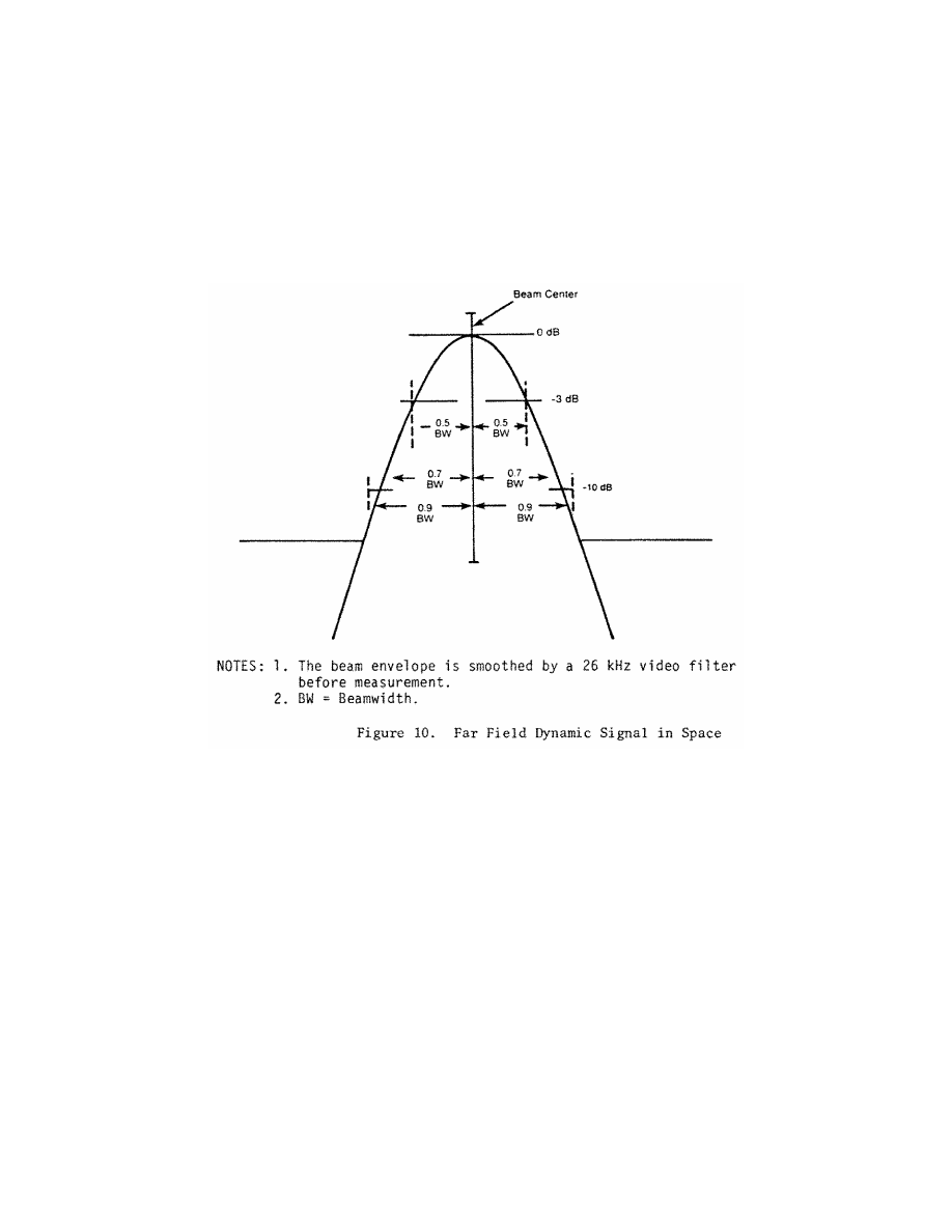
881
Federal Aviation Administration, DOT
§ 171.313
(5)
Antenna far field pattern in the
vertical plane.
The azimuth antenna
free space radiation pattern below the
horizon must have a slope of at least
¥
8 dB/degree at the horizon and all
sidelobes below the horizon must be at
least 13 dB below the pattern peak. The
antenna radiation pattern above the
horizon must satisfy both the system
coverage requirements and the spu-
rious radiation requirement.
(6)
Data antenna.
The data antenna
must have horizontal and vertical pat-
terns as required for its function.
(g)
Back azimuth coverage require-
ments.
The back azimuth equipment
where used must provide guidance in-
formation in at least the following vol-
ume of space (see Figure 11):
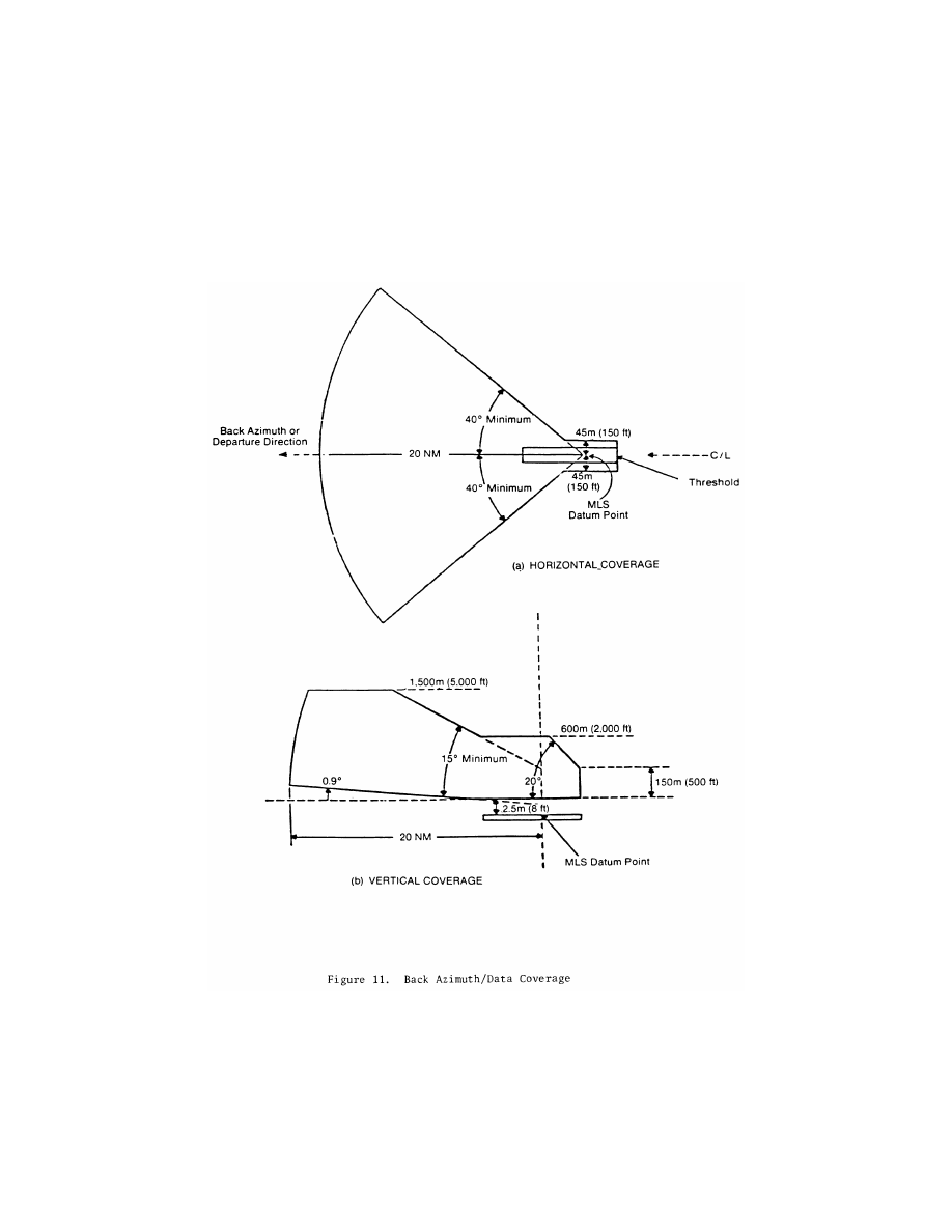
882
14 CFR Ch. I (1–1–24 Edition)
§ 171.313
(1) Horizontally within a sector
±
40
degrees about the runway centerline
originating at the back azimuth
ground equipment antenna and extend-
ing in the direction of the missed ap-
proach at least to 20 nautical miles
from the runway stop end. The min-
imum proportional guidance sector
must be
±
10 degrees about the runway
centerline. Clearance signals must be

883
Federal Aviation Administration, DOT
§ 171.313
used to provide the balance of the re-
quired coverage where the proportional
sector is less than
±
40 degrees.
(2) Vertically in the runway region
between:
(i) A horizontal surface 2.5 meters (8
feet) above the farthest point of run-
way centerline which is in line of sight
of the azimuth antenna, and,
(ii) A conical surface originating at
the azimuth ground equipment antenna
inclined at 20 degrees above the hori-
zontal up to a height of 600 meters (2000
feet).
(3) Vertically in the back azimuth re-
gion between:
(i) A conical surface originating 2.5
meters (8 feet) above the runway stop
end, included at 0.9 degree above the
horizontal, and,
(ii) A conical surface orginating at
the missed approach azimuth ground
equipment antenna, inclined at 15 de-
grees above the horizontal up to a
height of 1500 meters (5000 feet).
(iii) Where obstacles penetrate the
lower coverage limits, coverage need be
provided only to minimum line of
sight.
(4) Within the back azimuth coverage
sector defined in paragraph (q) (1), (2),
and (3) of this section the power den-
sities must not be less than those
shown in Table 9, but the equipment
design must also allow for:
(i) Transmitter power degradation
from normal
¥
1.5 dB.
(ii) Rain loss of
¥
2.2 dB at the longi-
tudinal coverage extremes.
(h)
Back azimuth siting.
The back azi-
muth equipment antenna must:
(1) Normally be located on the exten-
sion of the runway centerline at the
threshold end;
(2) Be adjusted so that the vertical
plane containing the zero degree course
line contains the back azimuth ref-
erence datum;
(3) Have minimum height necessary
to comply with the course require-
ments prescribed in paragraph (g) of
this section;
(4) Be located at a distance from the
threshold end that is consistent with
safe obstruction clearance practices;
(5) Not obscure any light of an ap-
proach lighting system; and
(6) Be installed on frangible mounts
or beyond the 300 meter (1000 feet) light
bar.
(i)
Back azimuth antenna coordinates.
The scanning beams transmitted by
the back azimuth equipment may be ei-
ther conical or planar.
(j)
Back azimuth accuracy.
The re-
quirements specified in § 171.313(e)
apply except that the reference point is
the back azimuth reference datum.
(k)
Back azimuth antenna characteris-
tics.
The requirements specified in
§ 171.313(f) apply.
(l)
Scanning conventions.
Figure 12
shows the approach azimuth and back
azimuth scanning conventions.
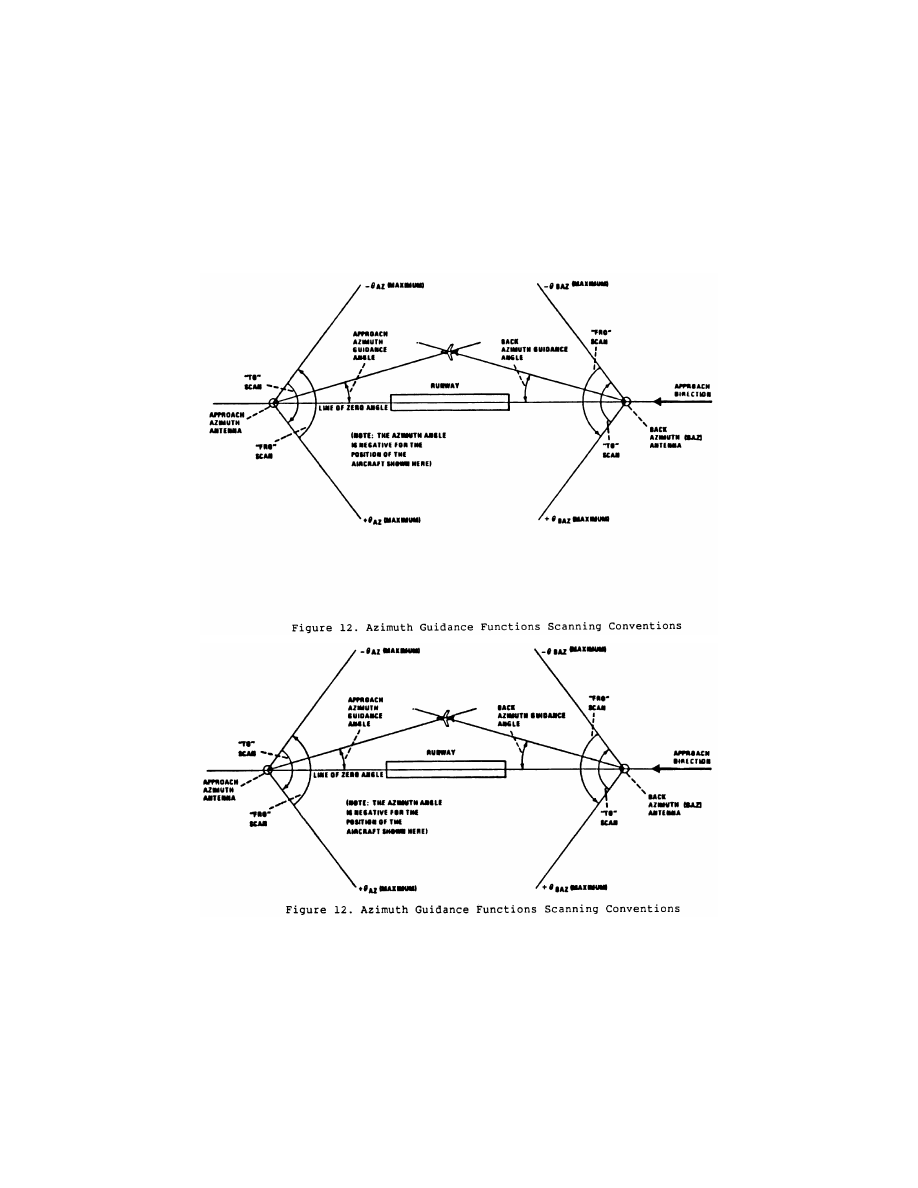
884
14 CFR Ch. I (1–1–24 Edition)
§ 171.313
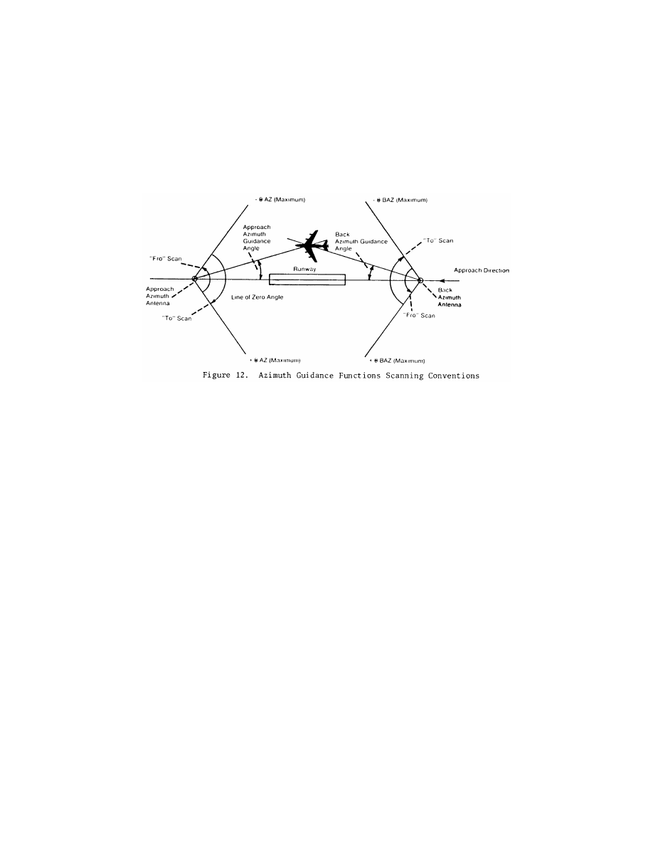
885
Federal Aviation Administration, DOT
§ 171.315
(m)
False guidance.
False courses
which can be acquired and tracked by
an aircraft shall not exist anywhere ei-
ther inside or outside of the MLS cov-
erage sector. False courses which exist
outside of the minimum coverage sec-
tor may be suppressed by the use of
OCI.
N
OTE
: False courses may be due to (but not
limited to) MLS airborne receiver acquisi-
tion of the following types of false guidance:
reflections of the scanning beam, scanning
beam antenna sidelobes and grating lobes,
and incorrect clearance.
§ 171.315 Azimuth monitor system re-
quirements.
(a) The approach azimuth or back
azimuth monitor system must cause
the radiation to cease and a warning
must be provided at the designated
control point if any of the following
conditions persist for longer than the
periods specified:
(1) There is a change in the ground
equipment contribution to the mean
course error component such that the
path following error at the reference
datum or in the direction of any azi-
muth radial, exceeds the limits speci-
fied in §§ 171.313(e)(1) or 171.313(j) for a
period of more than one second.
N
OTE
: The above requirement and the re-
quirement to limit the ground equipment
mean error to
±
10 ft. can be satisfied by the
following procedure. The integral monitor
alarm limit should be set to the angular
equivalent of
±
10 ft. at the approach ref-
erence datum. This will limit the electrical
component of the mean course error to
±
10
ft. The field monitor alarm limit should be
set such that with the mean course error at
the alarm limit the total allowed PFE is not
exceeded on any commissioned approach
course from the limit of coverage to an alti-
tude of 100 feet.
(2) There are errors in two consecu-
tive transmissions of Basic Data Words
1, 2, 4 or 5.
(3) There is a reduction in the radi-
ated power to a level not less than that
specified in §§ 171.313(a)(4) or
171.313(g)(4) for a period of more than
one second.
(4) There is an error in the preamble
DPSK transmissions which occurs
more than once in any one second pe-
riod.
(5) There is an error in the time divi-
sion multiplex synchronization of a
particular azimuth function that the
requirement specified in § 171.311(e) is
not satisfied and if this condition per-
sists for more than one second.
(6) A failure of the monitor is de-
tected.
(b) Radiation of the following
fuctions must cease and a warning pro-
vided at the designated control point if
there are errors in 2 consecutive trans-
missions:
(1) Morse Code Identification,
(2) Basic Data Words 3 and 6,
(3) Auxiliary Data Words.

886
14 CFR Ch. I (1–1–24 Edition)
§ 171.317
(c) The period during which erro-
neous guidance information is radiated
must not exceed the periods specified
in § 171.315(a). If the fault is not cleared
within the time allowed, the ground
equipment must be shut down. After
shutdown, no attempt must be made to
restore service until a period of 20 sec-
onds has elapsed.
§ 171.317 Approach elevation perform-
ance requirements.
This section prescribes the perform-
ance requirements for the elevation
equipment components of the MLS as
follows:
(a)
Elevation coverage requirements.
The approach elevation facility must
provide proportional guidance informa-
tion in at least the following volume of
space (see Figure 13):
(1) Laterally within a sector origi-
nating at the datum point which is at
least equal to the proportional guid-
ance sector provided by the approach
azimuth ground equipment.
(2) Longitudinally from 75 meters (250
feet) from the datum point to 20 nau-
tical miles from threshold in the direc-
tion of the approach.
(3) Vertically within the sector
bounded by:
(i) A surface which is the locus of
points 2.5 meters (8 feet) above the run-
way surface;
(ii) A conical surface originating at
the datum point and inclined 0.9 degree
above the horizontal and,
(iii) A conical surface originating at
the datum point and inclined at 15.0 de-
grees above the horizontal up to a
height of 6000 meters (20,000 feet).
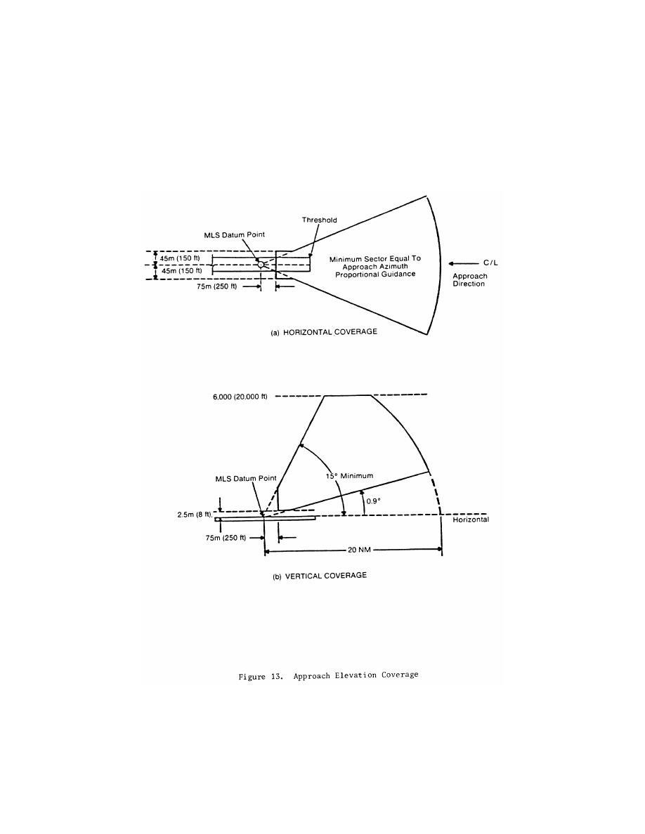
887
Federal Aviation Administration, DOT
§ 171.317
Where the physical characteristics of
the approach region prevent
theachievement of the standards under
paragraphs (a) (1), (2), and (3) of this
section, guidance need not be provided
below a conical surface originating at
the elevation antenna and inclined 0.9
degree above the line of sight.

888
14 CFR Ch. I (1–1–24 Edition)
§ 171.317
(4) Within the elevation coverage sec-
tor defined in paragraphs (a) (1), (2) and
(3) of this section, the power densities
must not be less than those shown in
Table 9, but the equipment design must
also allow for:
(i) Transmitter power degradation
from normal by
¥
1.5 dB.
(ii) Rain loss of
¥
2.2 dB at the cov-
erage extremes.
(b)
Elevation siting requirements.
The
Elevation Antenna System must:
(1) Be located as close to runway cen-
terline as possible (without violating
obstacle clearance criteria).
(2) Be located near runway threshold
such that the asymptote of the min-
imum glidepath crosses the threshold
of the runway at the Approach Ref-
erence Datum height. Normally, the
minimum glidepath should be 3 degrees
and the Approach Reference Datum
height should be 50 feet. However,
there are circumstances where other
glideslopes and reference datum
heights are appropriate. Some of these
instances are discussed in FAA Order
8260.34 (Glide Slope Threshold Crossing
Height Requirements) and Order 8260.3
(IFR Approval of MLS.)
(3) Be located such that the MLS Ap-
proach Reference Datum and ILS Ref-
erence Datum heights are coincident
within a tolerance of 3 feet when MLS
is installed on a runway already served
by an ILS. This requirement applies
only if the ILS glide slope is sited such
that the height of the reference datum
meets the requirements of FAA Order
8260.34.
(c)
Antenna coordinates.
The scanning
beams transmitted by the elevation
subsystem must be conical.
(d)
Elevation accuracy.
(1) The accura-
cies shown in Table 13 are required at
the approach reference datum. From
the approach reference datum to the
coverage limit, the PFE, PFN and CMN
limits shall be allowed to linearly in-
crease as follows:
(i) With distance along the runway
centerline extended at the minimum
glide path angle, by a factor of 1.2 for
the PFE and PFN limits and to
±
0.10
degree for the CMN limits;
(ii) With azimuth angle, from runway
centerline extended to the coverage ex-
treme, by a factor of 1.2 for the PFE
and PFN limits and by a factor of 2.0
for the CMN limits;
(iii) With increasing elevation angles
from + 3 degrees to + 15 degrees, by a
factor of 2.0 for the PFE and PFN lim-
its;
T
ABLE
13—E
LEVATION
A
CCURACIES AT THE
A
PPROACH
R
EFERENCE
D
ATUM
Error type
System
Angular error (degrees)
Ground sub-
system
Airborne
subsystem
4
PFE ....................
12
±
0.133
(
3
)
±
0.017
CMN ..................
1
±
0.050
±
0.020
±
0.010
Notes:
1
Includes errors due to ground and airborne equipment and
propagation effects.
2
The system PFN component must not exceed
±
0.087 de-
gree.
3
The mean (bias) error component contributed by the
ground equipment should not exceed
±
0.067 degree.
4
The airborne subsystem angular errors are provided for in-
formation only.
(iv) With decreasing elevation angle
from + 3 degrees (or 60% of the min-
imum glide path angle, whichever is
less) to the coverage extreme, by a fac-
tor of 3 for the PFE, PFN and CMN
limits; and
(v) Maximum angular limits. the
CMN limits shall not exceed
±
0.10 de-
gree in any coverage region within
±
10
degrees laterally of runway centerline
extended which is above the elevation
angle specified in (iv) above.
N
OTE
: It is desirable that the CMN not ex-
ceed
±
0.10 degree throughout the coverage re-
gion above the elevation angle specified in
paragraph (d)(1)(iv) of this section.
(2) The system and ground subsystem
accuracies shown in Table 13 are to be
demonstrated at commissioning as
maximum error limits. Subsequent to
commissioning, the accuracies are to
be considered at 95% probability limits.
(e) Elevation antenna characteristics
are as follows:
(1)
Drift.
Any elevation angle as en-
coded by the scanning beam at any
point within the coverage sector must
not vary more than 0.04 degree over the
range of service conditions specified in
§ 171.309(d) without the use of internal
environmental controls. Multipath ef-
fects are excluded from this require-
ment.
(2)
Beam pointing errors.
The elevation
angle as encoded by the scanning beam
at any point within the coverage sector

889
Federal Aviation Administration, DOT
§ 171.319
must not deviate from the true ele-
vation angle at that point by more
than
±
0.04 degree for elevation angles
from 2.5
°
to 3.5
°
. Above 3.5
°
these errors
may linearly increase to
±
0.1 degree at
7.5
°
. Multipath and drift effects are ex-
cluded from this requirement.
(3)
Antenna alignment.
The antenna
must be equipped with suitable optical,
electrical, or mechanical means or any
combination of the three, to align the
lowest operationally required glidepath
to the true glidepath angle with a max-
imum error of 0.01 degree. Addition-
ally, the elevation antenna bias adjust-
ment must be electronically steerable
at least to the monitor limits in steps
not greater than 0.005 degrees.
(4)
Antenna far field patterns in the
plane of scan.
On the lowest operation-
ally required glidepath, the antenna
mainlobe pattern must conform to Fig-
ure 10, and the beamwidth must be
such that in the installed environment,
no significant ground reflections of the
mainlobe exist. In any case, the beam-
width must not exceed 2 degrees. The
antenna mainlobe may be allowed to
broaden from the value at boresight by
a factor of 1/cos
q
, where
q
is the angle
of boresight. Anywhere within cov-
erage, the
¥
3 dB width of the antenna
mainlobe, while scanning normally,
must not be less than 25 microseconds
(0.5 degrees) or greater than 250 micro-
seconds (5 degrees). The sidelobe levels
must be as follows:
(i)
Dynamic sidelobe levels.
With the
antenna scanning normally, the dy-
namic sidelobe level that is detected by
a receiver at any point within the pro-
portional coverage sector must be
down at least 10 dB from the peak of
the mainlobe. Outside the proportional
coverage sector, the radiation from the
scanning beam antenna must be of
such a nature that receiver warnings
will not be removed or a suitable OCI
signal must be provided.
(ii)
Effective sidelobe levels.
With the
antenna scanning normally, the
sidelobe levels in the plane of scan
must be such that, when reflected from
the ground, the resultant PFE along
any glidepath does not exceed 0.083 de-
grees.
(5)
Antenna far field pattern in the hor-
izontal plane.
The horizontal pattern of
the antenna must gradually de-empha-
size the signal away from antenna
boresight. Typically, the horizontal
pattern should be reduced by at least 3
dB at 20 degrees off boresight and by at
least 6 dB at 40 degrees off boresight.
Depending on the actual multipath
conditions, the horizontal radiation
patterns may require more or less de-
emphasis.
(6)
Data antenna.
The data antenna
must have horizontal and vertical pat-
terns as required for its function.
(f)
False guidance.
False courses
which can be acquired and tracked by
an aircraft shall not exist anywhere ei-
ther inside or outside of the MLS cov-
erage sector. False courses which exist
outside of the minimum coverage sec-
tor may be suppressed by the use of
OCI.
N
OTE
: False courses may be due to (but not
limited to) MLS airborne receiver acquisi-
tion of the following types of false guidance:
reflections of the scanning beam and scan-
ning beam antenna sidelobes and grating
lobes.
§ 171.319 Approach elevation monitor
system requirements.
(a) The monitor system must act to
ensure that any of the following condi-
tions do not persist for longer than the
periods specified when:
(1) There is a change in the ground
component contribution to the mean
glidepath error component such that
the path following error on any glide-
path exceeds the limits specified in
§ 171.317(d) for a period of more than
one second.
N
OTE
: The above requirement and the re-
quirement to limit the ground equipment
mean error to
±
0.067 degree can be satisfied
by the following procedure. The integral
monitor alarm limit should be set to
±
0.067
degree. This will limit the electrical compo-
nent of mean glidepath error to
±
0.067 degree.
The field monitor alarm limit should be set
such that with the mean glidepath error at
the alarm limit the total allowed PFE is not
exceeded on any commissioned glidepath
from the limit of coverage to an altitude of
100 feet.
(2) There is a reduction in the radi-
ated power to a level not less than that
specified in § 171.317(a)(4) for a period of
more than one second.
(3) There is an error in the preamble
DPSK transmission which occurs more
than once in any one second period.

890
14 CFR Ch. I (1–1–24 Edition)
§ 171.321
(4) There is an error in the time divi-
sion multiplex synchronization of a
particular elevation function such that
the requirement specified in § 171.311(e)
is not satisfied and this condition per-
sists for more than one second.
(5) A failure of the monitor is de-
tected.
(b) The period during which erro-
neous guidance information is radiated
must not exceed the periods specified
in § 171.319(a). If the fault is not cleared
within the time allowed, radiation
shall cease. After shutdown, no at-
tempt must be made to restore service
until a period of 20 seconds has elapsed.
§ 171.321 DME and marker beacon per-
formance requirements.
(a) The DME equipment must meet
the performance requirements pre-
scribed in subpart G of the part. This
subpart imposes requirements that per-
formance features must comply with
International Standards and Rec-
ommended Practices, Aeronautical
Telecommunications, Vol. I of Annex
10 to ICAO. It is available from ICAO,
Aviation Building, 1080 University
Street, Montreal 101, Quebec, Canada,
Attention: Distribution Officer and
also available for inspection at the Na-
tional Archives and Records Adminis-
tration (NARA). For information on
the availability of this material at
NARA, call 202–741–6030, or go to:
http://
www.archives.gov/federal
_
register/
code
_
of
_
federal
_
regulations/ibr
_
loca-
tions.html.
(b) MLS marker beacon equipment
must meet the performance require-
ments prescribed in subpart H of this
part. This subpart imposes require-
ments that performance features must
comply with International Standards
and Recommended Practices, Aero-
nautical Telecommuncations, Vol. I of
Annex 10 to ICAO.
[Doc. No. 5034, 29 FR 11337, Aug. 6, 1964, as
amended at 69 FR 18803, Apr. 9, 2004]
§ 171.323 Fabrication and installation
requirements.
(a) The MLS facility must be perma-
nent and must be located, constructed,
and installed in accordance with best
commercial engineering practices,
using applicable electric and safety
codes and Federal Communications
Commission (FCC) licensing require-
ments and siting requirements of
§§ 171.313(b) and 171.317(b).
(b) The MLS facility components
must utilize solid state technology ex-
cept that traveling wave tube ampli-
fiers (TWTA) may be used. A maximum
level of common modularity must be
provided along with diagnostics to fa-
cilitate maintenance and trouble-
shooting.
(c) An approved monitoring capa-
bility must be provided which indicates
the status of the equipment at the site
and at a remotely located maintenance
area, with monitor capability that pro-
vides pre-alarm of impending system
failures. This monitoring feature must
be capable of transmitting the status
and pre-alarm over standard phone
lines to a remote section. In the event
the sponsor requests the FAA to as-
sume ownership of the facility, the
monitoring feature must also be capa-
ble of interfacing with FAA remote
monitoring requirements. This require-
ment may be complied with by the ad-
dition of optional software and/or hard-
ware in space provided in the original
equipment.
(d) The mean corrective maintenance
time of the MLS equipment must be
equal to or less than 0.5 hours with a
maximum corrective maintenance time
not to exceed 1.5 hours. This measure
applies to correction of unscheduled
failures of the monitor, transmitter
and associated antenna assemblies,
limited to unscheduled outage and out
of tolerance conditions.
(e) The mean-time-between-failures
of the MLS angle system must not be
less than 1,500 hours. This measure ap-
plies to unscheduled outage, out-of-tol-
erance conditions, and failures of the
monitor, transmitter, and associated
antenna assemblies.
(f) The MLS facility must have a reli-
able source of suitable primary power,
either from a power distribution sys-
tem or locally generated. Adequate
power capacity must be provided for
the operation of the MLS as well as the
test and working equipment of the
MLS.
(g) The MLS facility must have a
continuously engaged or floating bat-
tery power source for the continued
normal operation of the ground station

891
Federal Aviation Administration, DOT
§ 171.325
operation if the primary power fails. A
trickle charge must be supplied to re-
charge the batteries during the period
of available primary power. Upon loss
and subsequent restoration of power,
the battery must be restored to full
charge within 24 hours. When primary
power is applied, the state of the bat-
tery charge must not affect the oper-
ation of the MLS ground station. The
battery must allow continuation of
normal operation of the MLS facility
for at least 2 hours without the use of
additional sources of power. When the
system is operating from the battery
supply without prime power, the ra-
dome deicers and the environmental
system need not operate. The equip-
ment must meet all specification re-
quirements with or without batteries
installed.
(h) There must be a means for deter-
mining, from the ground, the perform-
ance of the system including antenna,
both initially and periodically.
(i) The facility must have, or be sup-
plemented by, ground, air, or landline
communications services. At facilities
within or immediately adjacent to con-
trolled airspace, that are intended for
use as instrument approach aids for an
airport, there must be ground air com-
munications or reliable communica-
tions (at least a landline telephone)
from the airport to the nearest FAA
air traffic control or communication
facility. Compliance with this para-
graph need not be shown at airports
where an adjacent FAA facility can
communicate with aircraft on the
ground at the airport and during the
entire proposed instrument approach
procedure. In addition, at low traffic
density airports within or immediately
adjacent to controlled airspace, and
where extensive delays are not a fac-
tor, the requirements of this paragraph
may be reduced to reliable communica-
tions from the airport to the nearest
FAA air traffic control or communica-
tions facility. If the adjacent FAA fa-
cility can communicate with aircraft
during the proposed instrument ap-
proach procedure down to the airport
surface or at least down to the min-
imum en route altitude, this would re-
quire at least a landline telephone.
(j) The location of the phase center
for all antennas must be clearly
marked on the antenna enclosures.
(k) The latitude, longitude and mean
sea level elevation of all MLS anten-
nas, runway threshold and runway stop
end must be determined by survey with
an accuracy of
±
3 meters (
±
10 feet) lat-
erally and
±
0.3 meter (
±
1.0 foot)
vertically. The relative lateral and
vertical offsets of all antenna phase
centers, and both runway ends must be
determined with an accuracy of
±
0.3
meter (
±
1.0 foot) laterally and
±
0.03
meter (
±
0.1 foot) vertically. The owner
must bear all costs of the survey. The
results of this survey must be included
in the ‘‘operations and maintenance’’
manual required by section 171.325 of
this subpart and will be noted on FAA
Form 198 required by § 171.327.
[Doc. No. 20669, 51 FR 33177, Sept. 18, 1986, as
amended by Amdt. 171–16, 56 FR 65665, Dec.
17, 1991]
§ 171.325 Maintenance and operations
requirements.
(a) The owner of the facility must es-
tablish an adequate maintenance sys-
tem and provide MLS qualified mainte-
nance personnel to maintain the facil-
ity at the level attained at the time it
was commissioned. Each person who
maintains a facility must meet the
FCC licensing requirements and dem-
onstrate that he has the special knowl-
edge and skills needed to maintain an
MLS facility, including proficiency in
maintenance procedures and the use of
specialized test equipment.
(b) In the event of out-of-tolerance
conditions or malfunctions, as evi-
denced by receiving two successive
pilot reports, the owner must close the
facility by encasing radiation, and
issue a ‘‘Notice to Airmen’’ (NOTAM)
that the facility is out of service.
(c) The owner must prepare, and ob-
tain approval of, an operations and
maintenance manual that sets forth
mandatory procedures for operations,
periodic maintenance, and emergency
maintenance, including instructions on
each of the following:
(1) Physical security of the facility.
(2) Maintenance and operations by
authorized persons.
(3) FCC licensing requirements for
operations and maintenance personnel.

892
14 CFR Ch. I (1–1–24 Edition)
§ 171.325
(4) Posting of licenses and signs.
(5) Relations between the facility and
FAA air traffic control facilities, with
a description of the boundaries of con-
trolled airspace over or near the facil-
ity, instructions for relaying air traffic
control instructions and information,
if applicable, and instructions for the
operation of an air traffic advisory
service if the facility is located outside
of controlled airspace.
(6) Notice to the Administrator of
any suspension of service.
(7) Detailed and specific maintenance
procedures and servicing guides stating
the frequency of servicing.
(8) Air-ground communications, if
provided, expressly written or incor-
porating appropriate sections of FAA
manuals by reference.
(9) Keeping the station logs and other
technical reports, and the submission
of reports required by § 171.327.
(10) Monitoring of the MLS facility.
(11) Inspections by United States per-
sonnel.
(12) Names, addresses, and telephone
numbers of persons to be notified in an
emergency.
(13) Shutdowns for periodic mainte-
nance and issuing of NOTAM for rou-
tine or emergency shutdowns.
(14) Commissioning of the MLS facil-
ity.
(15) An acceptable procedure for
amending or revising the manual.
(16) An explanation of the kinds of
activities (such as construction or
grading) in the vicinity of the MLS fa-
cility that may require shutdown or re-
certification of the MLS facility by
FAA flight check.
(17) Procedures for conducting a
ground check of the azimuth and ele-
vation alignment.
(18) The following information con-
cerning the MLS facility:
(i) Facility component locations with
respect to airport layout, instrument
runways, and similar areas.
(ii) The type, make and model of the
basic radio equipment that provides
the service including required test
equipment.
(iii) The station power emission,
channel, and frequency of the azimuth,
elevation, DME, marker beacon, and
associated compass locators, if any.
(iv) The hours of operation.
(v) Station identification call letters
and method of station identification
and the time spacing of the identifica-
tion.
(vi) A description of the critical parts
that may not be changed, adjusted, or
repaired without an FAA flight check
to confirm published operations.
(d) The owner or his maintenance
representative must make a ground
check of the MLS facility periodically
in accordance with procedures ap-
proved by the FAA at the time of com-
missioning, and must report the results
of the checks as provided in § 171.327.
(e) The only modifications permitted
are those that are submitted to FAA
for approval by the MLS equipment
manufacturer. The owner or sponsor of
the facility must incorporate these
modifications in the MLS equipment.
Associated changes must also be made
to the operations and maintenance
manual required in paragraph (c) of
this section. This and all other correc-
tions and additions to this operations
and maintenance manual must also be
submitted to FAA for approval.
(f) The owner or the owner’s mainte-
nance representative must participate
in inspections made by the FAA.
(g) The owner must ensure the avail-
ability of a sufficient stock of spare
parts, including solid state compo-
nents, or modules to make possible the
prompt replacement of components or
modules that fail or deteriorate in
service.
(h) FAA approved test instruments
must be used for maintenance of the
MLS facility.
(i) Inspection consists of an examina-
tion of the MLS equipment to ensure
that unsafe operating conditions do not
exist.
(j) Monitoring of the MLS radiated
signal must ensure a high degree of in-
tegrity and minimize the requirements
for ground and flight inspection. The
monitor must be checked daily during
the in-service test evaluation period (96
hour burn in) for calibration and sta-
bility. These tests and ground checks
or azimuth, elevation, DME, and mark-
er beacon radiation characteristics
must be conducted in accordance with
the maintenance requirements of this
section.

893
Federal Aviation Administration, DOT
§ 171.327
§ 171.327 Operational records.
The owner of the MLS facility or his
maintenance representative must sub-
mit the following operational records
at the indicated time to the appro-
priate FAA regional office where the
facility is located.
(a)
Facility Equipment Performance &
Adjustment Data (FAA Form 198).
The
FAA Form 198 shall be filled out by the
owner or his maintenance representa-
tive with the equipment adjustments
and meter readings as of the time of fa-
cility commissioning. One copy must
be kept in the permanent records of the
facility and two copies must be sent to
the appropriate FAA regional office.
The owner or his maintenance rep-
resentative must revise the FAA Form
198 data after any major repair, mod-
ernization, or retuning to reflect an ac-
curate record of facility operation and
adjustment.
(b)
Facility Maintenance Log (FAA
Form 6030–1).
FAA Form 6030–1 is per-
manent record of all the activities re-
quired to maintain the MLS facility.
The entries must include all malfunc-
tions met in maintaining the facility
including information on the kind of
work and adjustments made, equip-
ment failures, causes (if determined)
and corrective action taken. In addi-
tion, the entries must include comple-
tion of periodic maintenance required
to maintain the facility. The owner or
his maintenance representative must
keep the original of each form at the
facility and send a copy to the appro-
priate FAA regional office at the end of
each month in which it is prepared.
However, where an FAA approved re-
mote monitoring system is installed
which precludes the need for periodic
maintenance visits to the facility,
monthly reports from the remote mon-
itoring system control point must be
forwarded to the appropriate FAA re-
gional office, and a hard copy retained
at the control point.
(c)
Technical Performance Record (FAA
Form 6830 (formerly FAA Form 418)).
This
form contains a record of system pa-
rameters as specified in the manufac-
turer’s equipment manual. This data
will be recorded on each scheduled visit
to the facility. The owner or his main-
tenance representative shall keep the
original of each record at the facility
and send a copy of the form to the ap-
propriate FAA regional office.