
211
Federal Aviation Administration, DOT
§ 25.109
(A) 110 percent of V
MU
in the all-en-
gines-operating condition, and 105 per-
cent of V
MU
determined at the thrust-
to-weight ratio corresponding to the
one-engine-inoperative condition; or
(B) If the V
MU
attitude is limited by
the geometry of the airplane (
i.e., tail
contact with the runway), 108 percent
of V
MU
in the all-engines-operating
condition, and 104 percent of V
MU
deter-
mined at the thrust-to-weight ratio
corresponding to the one-engine-inop-
erative condition.
(2) For any given set of conditions
(such as weight, configuration, and
temperature), a single value of
V
R,
ob-
tained in accordance with this para-
graph, must be used to show compli-
ance with both the one-engine-inoper-
ative and the all-engines-operating
takeoff provisions.
(3) It must be shown that the one-en-
gine-inoperative takeoff distance,
using a rotation speed of 5 knots less
than
V
R
established in accordance with
paragraphs (e)(1) and (2) of this section,
does not exceed the corresponding one-
engine-inoperative takeoff distance
using the established
V
R
. The takeoff
distances must be determined in ac-
cordance with § 25.113(a)(1).
(4) Reasonably expected variations in
service from the established takeoff
procedures for the operation of the air-
plane (such as over-rotation of the air-
plane and out-of-trim conditions) may
not result in unsafe flight characteris-
tics or in marked increases in the
scheduled takeoff distances established
in accordance with § 25.113(a).
(f)
V
LOF
is the calibrated airspeed at
which the airplane first becomes air-
borne.
(g)
V
FTO
, in terms of calibrated air-
speed, must be selected by the appli-
cant to provide at least the gradient of
climb required by § 25.121(c), but may
not be less than—
(1) 1.18
V
SR
; and
(2) A speed that provides the maneu-
vering capability specified in § 25.143(h).
(h) In determining the takeoff speeds
V
1
, V
R
, and V
2
for flight in icing condi-
tions, the values of V
MCG
, V
MC
, and V
MU
determined for non-icing conditions
may be used.
[Doc. No. 5066, 29 FR 18291, Dec. 24, 1964, as
amended by Amdt. 25–38, 41 FR 55466, Dec. 20,
1976; Amdt. 25–42, 43 FR 2320, Jan. 16, 1978;
Amdt. 25–92, 63 FR 8318, Feb. 18, 1998; Amdt.
25–94, 63 FR 8848, Feb. 23, 1998; Amdt. 25–108,
67 FR 70826, Nov. 26, 2002; Amdt. 25–121, 72 FR
44665, Aug. 8, 2007; Amdt. 25–135, 76 FR 74654,
Dec. 1, 2011]
§ 25.109
Accelerate-stop distance.
(a) The accelerate-stop distance on a
dry runway is the greater of the fol-
lowing distances:
(1) The sum of the distances nec-
essary to—
(i) Accelerate the airplane from a
standing start with all engines oper-
ating to V
EF
for takeoff from a dry run-
way;
(ii) Allow the airplane to accelerate
from V
EF
to the highest speed reached
during the rejected takeoff, assuming
the critical engine fails at V
EF
and the
pilot takes the first action to reject
the takeoff at the V
1
for takeoff from a
dry runway; and
(iii) Come to a full stop on a dry run-
way from the speed reached as pre-
scribed in paragraph (a)(1)(ii) of this
section; plus
(iv) A distance equivalent to 2 sec-
onds at the V
1
for takeoff from a dry
runway.
(2) The sum of the distances nec-
essary to—
(i) Accelerate the airplane from a
standing start with all engines oper-
ating to the highest speed reached dur-
ing the rejected takeoff, assuming the
pilot takes the first action to reject
the takeoff at the V
1
for takeoff from a
dry runway; and
(ii) With all engines still operating,
come to a full stop on dry runway from
the speed reached as prescribed in para-
graph (a)(2)(i) of this section; plus
(iii) A distance equivalent to 2 sec-
onds at the V
1
for takeoff from a dry
runway.
(b) The accelerate-stop distance on a
wet runway is the greater of the fol-
lowing distances:
(1) The accelerate-stop distance on a
dry runway determined in accordance
with paragraph (a) of this section; or
(2) The accelerate-stop distance de-
termined in accordance with paragraph
VerDate Sep<11>2014
09:06 Jun 28, 2024
Jkt 262046
PO 00000
Frm 00221
Fmt 8010
Sfmt 8010
Y:\SGML\262046.XXX
262046
jspears on DSK121TN23PROD with CFR
212
14 CFR Ch. I (1–1–24 Edition)
§ 25.109
(a) of this section, except that the run-
way is wet and the corresponding wet
runway values of V
EF
and V
1
are used.
In determining the wet runway accel-
erate-stop distance, the stopping force
from the wheel brakes may never ex-
ceed:
(i) The wheel brakes stopping force
determined in meeting the require-
ments of § 25.101(i) and paragraph (a) of
this section; and
(ii) The force resulting from the wet
runway braking coefficient of friction
determined in accordance with para-
graphs (c) or (d) of this section, as ap-
plicable, taking into account the dis-
tribution of the normal load between
braked and unbraked wheels at the
most adverse center-of-gravity position
approved for takeoff.
(c) The wet runway braking coeffi-
cient of friction for a smooth wet run-
way is defined as a curve of friction co-
efficient versus ground speed and must
be computed as follows:
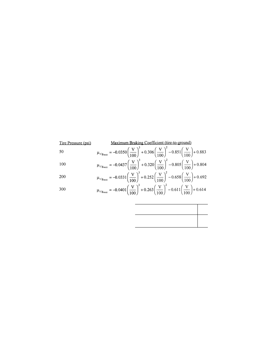
(1) The maximum tire-to-ground wet
runway braking coefficient of friction
is defined as:
Where—
Tire Pressure = maximum airplane operating
tire pressure (psi);
μ
t/gMAX
= maximum tire-to-ground braking
coefficient;
V = airplane true ground speed (knots); and
Linear interpolation may be used for tire
pressures other than those listed.
(2) The maximum tire-to-ground wet
runway braking coefficient of friction
must be adjusted to take into account
the efficiency of the anti-skid system
on a wet runway. Anti-skid system op-
eration must be demonstrated by flight
testing on a smooth wet runway, and
its efficiency must be determined. Un-
less a specific anti-skid system effi-
ciency is determined from a quan-
titative analysis of the flight testing
on a smooth wet runway, the max-
imum tire-to-ground wet runway brak-
ing coefficient of friction determined
in paragraph (c)(1) of this section must
be multiplied by the efficiency value
associated with the type of anti-skid
system installed on the airplane:
Type of anti-skid system
Effi-
ciency
value
On-Off ........................................................................
0.30
Quasi-Modulating .......................................................
0.50
Fully Modulating ........................................................
0.80
(d) At the option of the applicant, a
higher wet runway braking coefficient
of friction may be used for runway sur-
faces that have been grooved or treated
with a porous friction course material.
For grooved and porous friction course
runways, the wet runway braking
coefficent of friction is defined as ei-
ther:
(1) 70 percent of the dry runway brak-
ing coefficient of friction used to deter-
mine the dry runway accelerate-stop
distance; or
(2) The wet runway braking coeffi-
cient defined in paragraph (c) of this
section, except that a specific anti-skid
VerDate Sep<11>2014
09:06 Jun 28, 2024
Jkt 262046
PO 00000
Frm 00222
Fmt 8010
Sfmt 8010
Y:\SGML\262046.XXX
262046
ER18FE98.004</GPH>
jspears on DSK121TN23PROD with CFR
213
Federal Aviation Administration, DOT
§ 25.111
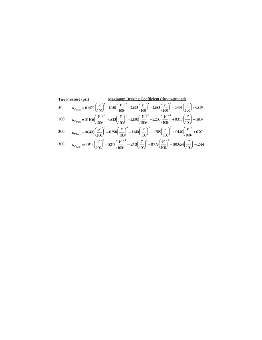
system efficiency, if determined, is ap-
propriate for a grooved or porous fric-
tion course wet runway, and the max-
imum tire-to-ground wet runway brak-
ing coefficient of friction is defined as:
Where—
Tire Pressure = maximum airplane operating
tire pressure (psi);
μ
t/gMAX
= maximum tire-to-ground braking
coefficient;
V = airplane true ground speed (knots); and
Linear interpolation may be used for tire
pressures other than those listed.
(e) Except as provided in paragraph
(f)(1) of this section, means other than
wheel brakes may be used to determine
the accelerate-stop distance if that
means—
(1) Is safe and reliable;
(2) Is used so that consistent results
can be expected under normal oper-
ating conditions; and
(3) Is such that exceptional skill is
not required to control the airplane.
(f) The effects of available reverse
thrust—
(1) Shall not be included as an addi-
tional means of deceleration when de-
termining the accelerate-stop distance
on a dry runway; and
(2) May be included as an additional
means of deceleration using rec-
ommended reverse thrust procedures
when determining the accelerate-stop
distance on a wet runway, provided the
requirements of paragraph (e) of this
section are met.
(g) The landing gear must remain ex-
tended throughout the accelerate-stop
distance.
(h) If the accelerate-stop distance in-
cludes a stopway with surface charac-
teristics substantially different from
those of the runway, the takeoff data
must include operational correction
factors for the accelerate-stop dis-
tance. The correction factors must ac-
count for the particular surface charac-
teristics of the stopway and the vari-
ations in these characteristics with
seasonal weather conditions (such as
temperature, rain, snow, and ice) with-
in the established operational limits.
(i) A flight test demonstration of the
maximum brake kinetic energy accel-
erate-stop distance must be conducted
with not more than 10 percent of the
allowable brake wear range remaining
on each of the airplane wheel brakes.
[Doc. No. 5066, 29 FR 18291, Dec. 24, 1964, as
amended by Amdt. 25–42, 43 FR 2321, Jan. 16,
1978; Amdt. 25–92, 63 FR 8318, Feb. 18, 1998]
§ 25.111
Takeoff path.
(a) The takeoff path extends from a
standing start to a point in the takeoff
at which the airplane is 1,500 feet above
the takeoff surface, or at which the
transition from the takeoff to the en
route configuration is completed and
V
FTO
is reached, whichever point is
higher. In addition—
(1) The takeoff path must be based on
the procedures prescribed in § 25.101(f);
(2) The airplane must be accelerated
on the ground to
V
EF,
at which point
the critical engine must be made inop-
erative and remain inoperative for the
rest of the takeoff; and
VerDate Sep<11>2014
09:06 Jun 28, 2024
Jkt 262046
PO 00000
Frm 00223
Fmt 8010
Sfmt 8010
Y:\SGML\262046.XXX
262046
ER18FE98.005</GPH>
jspears on DSK121TN23PROD with CFR