218
14 CFR Ch. I (1–1–24 Edition)
§ 25.143
more than 5 knots CAS at the max-
imum landing weight.
(b) In determining the distance in
paragraph (a) of this section:
(1) The airplane must be in the land-
ing configuration.
(2) A stabilized approach, with a cali-
brated airspeed of not less than V
REF
,
must be maintained down to the 50-foot
height.
(i) In non-icing conditions, V
REF
may
not be less than:
(A) 1.23 V
SR
0;
(B) V
MCL
established under § 25.149(f);
and
(C) A speed that provides the maneu-
vering capability specified in § 25.143(h).
(ii) In icing conditions, V
REF
may not
be less than:
(A) The speed determined in para-
graph (b)(2)(i) of this section;
(B) 1.23 V
SR0
with the most critical of
the landing ice accretion(s) defined in
Appendices C and O of this part, as ap-
plicable, in accordance with § 25.21(g), if
that speed exceeds V
REF
selected for
non-icing conditions by more than 5
knots CAS; and
(C) A speed that provides the maneu-
vering capability specified in § 25.143(h)
with the most critical of the landing
ice accretion(s) defined in Appendices C
and O of this part, as applicable, in ac-
cordance with § 25.21(g).
(3) Changes in configuration, power
or thrust, and speed, must be made in
accordance with the established proce-
dures for service operation.
(4) The landing must be made with-
out excessive vertical acceleration,
tendency to bounce, nose over, ground
loop, porpoise, or water loop.
(5) The landings may not require ex-
ceptional piloting skill or alertness.
(c) For landplanes and amphibians,
the landing distance on land must be
determined on a level, smooth, dry,
hard-surfaced runway. In addition—
(1) The pressures on the wheel brak-
ing systems may not exceed those spec-
ified by the brake manufacturer;
(2) The brakes may not be used so as
to cause excessive wear of brakes or
tires; and
(3) Means other than wheel brakes
may be used if that means—
(i) Is safe and reliable;
(ii) Is used so that consistent results
can be expected in service; and
(iii) Is such that exceptional skill is
not required to control the airplane.
(d) For seaplanes and amphibians,
the landing distance on water must be
determined on smooth water.
(e) For skiplanes, the landing dis-
tance on snow must be determined on
smooth, dry, snow.
(f) The landing distance data must
include correction factors for not more
than 50 percent of the nominal wind
components along the landing path op-
posite to the direction of landing, and
not less than 150 percent of the nomi-
nal wind components along the landing
path in the direction of landing.
(g) If any device is used that depends
on the operation of any engine, and if
the landing distance would be notice-
ably increased when a landing is made
with that engine inoperative, the land-
ing distance must be determined with
that engine inoperative unless the use
of compensating means will result in a
landing distance not more than that
with each engine operating.
[Amdt. 25–121, 72 FR 44666; Aug. 8, 2007; 72 FR
50467, Aug. 31, 2007; Amdt. 25–140, 79 FR 65525,
Nov. 4, 2014]
C
ONTROLLABILITY AND
M
ANEUVERABILITY
§ 25.143
General.
(a) The airplane must be safely con-
trollable and maneuverable during—
(1) Takeoff;
(2) Climb;
(3) Level flight;
(4) Descent; and
(5) Landing.
(b) It must be possible to make a
smooth transition from one flight con-
dition to any other flight condition
without exceptional piloting skill,
alertness, or strength, and without
danger of exceeding the airplane limit-
load factor under any probable oper-
ating conditions, including—
(1) The sudden failure of the critical
engine;
(2) For airplanes with three or more
engines, the sudden failure of the sec-
ond critical engine when the airplane is
in the en route, approach, or landing
configuration and is trimmed with the
critical engine inoperative; and
VerDate Sep<11>2014
09:06 Jun 28, 2024
Jkt 262046
PO 00000
Frm 00228
Fmt 8010
Sfmt 8010
Y:\SGML\262046.XXX
262046
jspears on DSK121TN23PROD with CFR
219
Federal Aviation Administration, DOT
§ 25.143
(3) Configuration changes, including
deployment or retraction of decelera-
tion devices.
(c) The airplane must be shown to be
safely controllable and maneuverable
with the most critical of the ice accre-
tion(s) appropriate to the phase of
flight as defined in Appendices C and O
of this part, as applicable, in accord-
ance with § 25.21(g), and with the crit-
ical engine inoperative and its pro-
peller (if applicable) in the minimum
drag position:
(1) At the minimum V
2
for takeoff;
(2) During an approach and go-
around; and
(3) During an approach and landing.
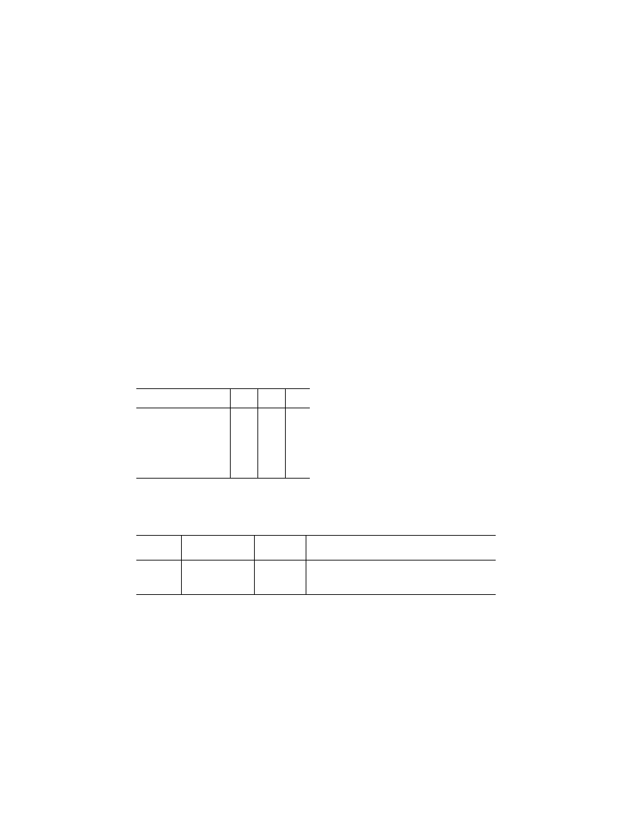
(d) The following table prescribes, for
conventional wheel type controls, the
maximum control forces permitted
during the testing required by para-
graph (a) through (c) of this section:
Force, in pounds, applied to the
control wheel or rudder pedals
Pitch Roll Yaw
For short term application for
pitch and roll control—two
hands available for control ....
75
50
For short term application for
pitch and roll control—one
hand available for control ......
50
25
For short term application for
yaw control .............................
150
For long term application ..........
10
5
20
(e) Approved operating procedures or
conventional operating practices must
be followed when demonstrating com-
pliance with the control force limita-
tions for short term application that
are prescribed in paragraph (d) of this
section. The airplane must be in trim,
or as near to being in trim as practical,
in the preceding steady flight condi-
tion. For the takeoff condition, the air-
plane must be trimmed according to
the approved operating procedures.
(f) When demonstrating compliance
with the control force limitations for
long term application that are pre-
scribed in paragraph (d) of this section,
the airplane must be in trim, or as near
to being in trim as practical.
(g) When maneuvering at a constant
airspeed or Mach number (up to V
FC
/
M
FC
), the stick forces and the gradient
of the stick force versus maneuvering
load factor must lie within satisfactory
limits. The stick forces must not be so
great as to make excessive demands on
the pilot’s strength when maneuvering
the airplane, and must not be so low
that the airplane can easily be over-
stressed inadvertently. Changes of gra-
dient that occur with changes of load
factor must not cause undue difficulty
in maintaining control of the airplane,
and local gradients must not be so low
as to result in a danger of overcontrol-
ling.
(h) The maneuvering capabilities in a
constant speed coordinated turn at for-
ward center of gravity, as specified in
the following table, must be free of
stall warning or other characteristics
that might interfere with normal ma-
neuvering:
Configuration Speed
Maneuvering
bank angle in a
coordinated turn
Thrust/power setting
Takeoff ..........
V
2
30
°
Asymmetric WAT-Limited.
1
Takeoff ..........
2
V
2
+ XX
40
°
All-engines-operating climb.
3
En route ........
V
FTO
40
°
Asymmetric WAT-Limited.
1
Landing .........
V
REF
40
°
Symmetric for
¥
3
°
flight path angle.
1
A combination of weight, altitude, and temperature (WAT) such that the thrust or power setting produces the minimum climb
gradient specified in § 25.121 for the flight condition.
2
Airspeed approved for all-engines-operating initial climb.
3
That thrust or power setting which, in the event of failure of the critical engine and without any crew action to adjust the thrust
or power of the remaining engines, would result in the thrust or power specified for the takeoff condition at V
2
, or any lesser
thrust or power setting that is used for all-engines-operating initial climb procedures.
(i) When demonstrating compliance
with § 25.143 in icing conditions—
(1) Controllability must be dem-
onstrated with the most critical of the
ice accretion(s) for the particular
flight phase as defined in Appendices C
and O of this part, as applicable, in ac-
cordance with § 25.21(g);
(2) It must be shown that a push force
is required throughout a pushover ma-
neuver down to a zero g load factor, or
the lowest load factor obtainable if
limited by elevator power or other de-
sign characteristic of the flight control
system. It must be possible to prompt-
ly recover from the maneuver without
VerDate Sep<11>2014
09:06 Jun 28, 2024
Jkt 262046
PO 00000
Frm 00229
Fmt 8010
Sfmt 8010
Y:\SGML\262046.XXX
262046
jspears on DSK121TN23PROD with CFR

220
14 CFR Ch. I (1–1–24 Edition)
§ 25.145
exceeding a pull control force of 50
pounds; and
(3) Any changes in force that the
pilot must apply to the pitch control to
maintain speed with increasing sideslip
angle must be steadily increasing with
no force reversals, unless the change in
control force is gradual and easily con-
trollable by the pilot without using ex-
ceptional piloting skill, alertness, or
strength.
(j) For flight in icing conditions be-
fore the ice protection system has been
activated and is performing its in-
tended function, it must be dem-
onstrated in flight with the most crit-
ical of the ice accretion(s) defined in
Appendix C, part II, paragraph (e) of
this part and Appendix O, part II, para-
graph (d) of this part, as applicable, in
accordance with § 25.21(g), that:
(1) The airplane is controllable in a
pull-up maneuver up to 1.5 g load fac-
tor; and
(2) There is no pitch control force re-
versal during a pushover maneuver
down to 0.5 g load factor.
[Doc. No. 5066, 29 FR 18291, Dec. 24, 1964, as
amended by Amdt. 25–42, 43 FR 2321, Jan. 16,
1978; Amdt. 25–84, 60 FR 30749, June 9, 1995;
Amdt. 25–108, 67 FR 70826, Nov. 26, 2002;
Amdt. 25–121, 72 FR 44667, Aug. 8, 2007; Amdt.
25–129, 74 FR 38339, Aug. 3, 2009; Amdt. 25–140,
79 FR 65525, Nov. 4, 2014]
§ 25.145
Longitudinal control.
(a) It must be possible, at any point
between the trim speed prescribed in
§ 25.103(b)(6) and stall identification (as
defined in § 25.201(d)), to pitch the nose
downward so that the acceleration to
this selected trim speed is prompt with
(1) The airplane trimmed at the trim
speed prescribed in § 25.103(b)(6);
(2) The landing gear extended;
(3) The wing flaps (i) retracted and
(ii) extended; and
(4) Power (i) off and (ii) at maximum
continuous power on the engines.
(b) With the landing gear extended,
no change in trim control, or exertion
of more than 50 pounds control force
(representative of the maximum short
term force that can be applied readily
by one hand) may be required for the
following maneuvers:
(1) With power off, flaps retracted,
and the airplane trimmed at 1.3 V
SR1
,
extend the flaps as rapidly as possible
while maintaining the airspeed at ap-
proximately 30 percent above the ref-
erence stall speed existing at each in-
stant throughout the maneuver.
(2) Repeat paragraph (b)(1) except ini-
tially extend the flaps and then retract
them as rapidly as possible.
(3) Repeat paragraph (b)(2), except at
the go-around power or thrust setting.
(4) With power off, flaps retracted,
and the airplane trimmed at 1.3 V
SR1
,
rapidly set go-around power or thrust
while maintaining the same airspeed.
(5) Repeat paragraph (b)(4) except
with flaps extended.
(6) With power off, flaps extended,
and the airplane trimmed at 1.3 V
SR1
,
obtain and maintain airspeeds between
V
SW
and either 1.6 V
SR1
or V
FE
, which-
ever is lower.
(c) It must be possible, without ex-
ceptional piloting skill, to prevent loss
of altitude when complete retraction of
the high lift devices from any position
is begun during steady, straight, level
flight at 1.08 V
SR1
for propeller powered
airplanes, or 1.13 V
SR1
for turbojet pow-
ered airplanes, with—
(1) Simultaneous movement of the
power or thrust controls to the go-
around power or thrust setting;
(2) The landing gear extended; and
(3) The critical combinations of land-
ing weights and altitudes.
(d) If gated high-lift device control
positions are provided, paragraph (c) of
this section applies to retractions of
the high-lift devices from any position
from the maximum landing position to
the first gated position, between gated
positions, and from the last gated posi-
tion to the fully retracted position.
The requirements of paragraph (c) of
this section also apply to retractions
from each approved landing position to
the control position(s) associated with
the high-lift device configuration(s)
used to establish the go-around proce-
dure(s) from that landing position. In
addition, the first gated control posi-
tion from the maximum landing posi-
tion must correspond with a configura-
tion of the high-lift devices used to es-
tablish a go-around procedure from a
landing configuration. Each gated con-
trol position must require a separate
and distinct motion of the control to
pass through the gated position and
VerDate Sep<11>2014
09:06 Jun 28, 2024
Jkt 262046
PO 00000
Frm 00230
Fmt 8010
Sfmt 8010
Y:\SGML\262046.XXX
262046
jspears on DSK121TN23PROD with CFR