240
14 CFR Ch. I (1–1–24 Edition)
§ 25.343
for the maximum response at the na-
celle center of gravity derived from the
following dynamic gust conditions ap-
plied to the airplane:
(1) A discrete gust determined in ac-
cordance with § 25.341(a) at each angle
normal to the flight path, and sepa-
rately,
(2) A pair of discrete gusts, one
vertical and one lateral. The length of
each of these gusts must be independ-
ently tuned to the maximum response
in accordance with § 25.341(a). The pene-
tration of the airplane in the combined
gust field and the phasing of the
vertical and lateral component gusts
must be established to develop the
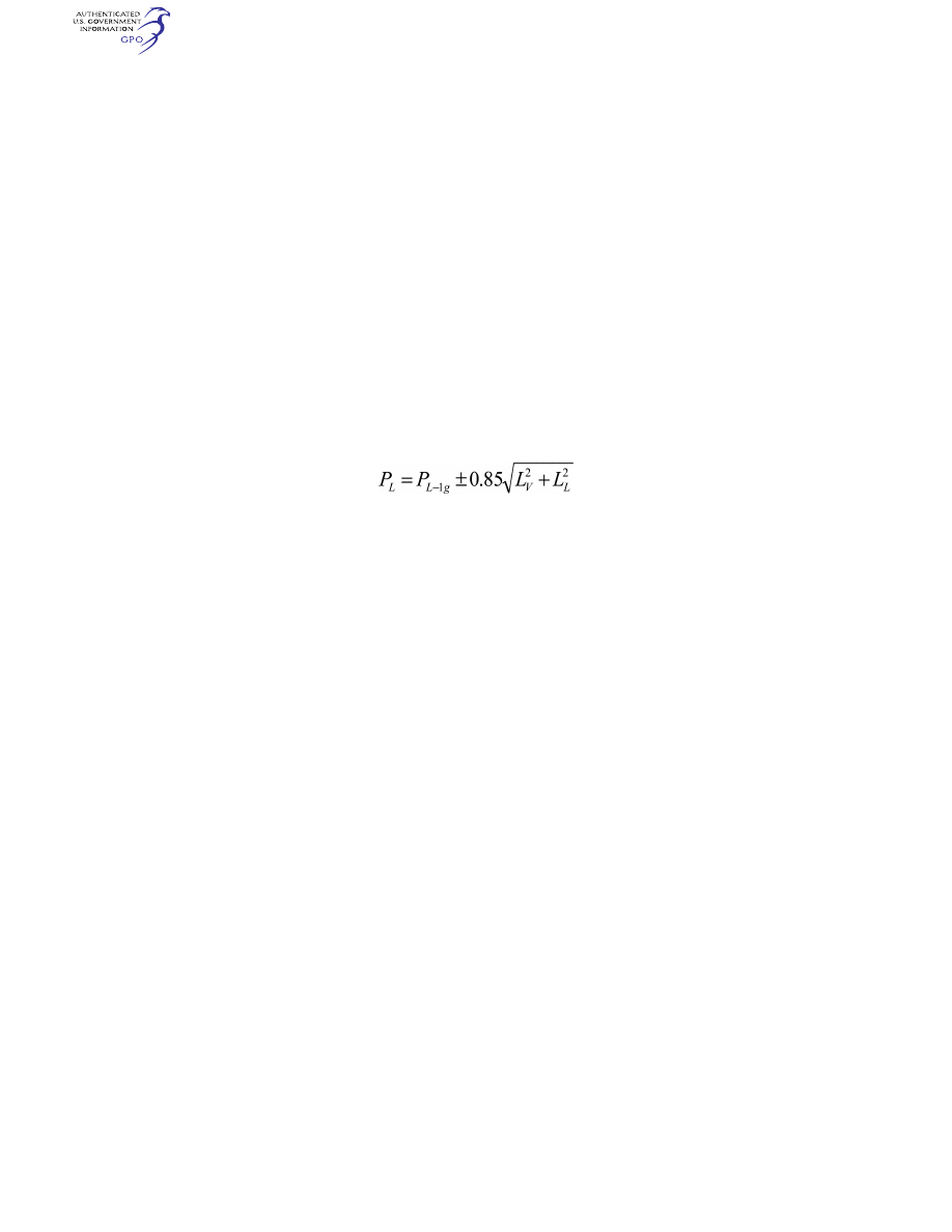
maximum response to the gust pair. In
the absence of a more rational anal-
ysis, the following formula must be
used for each of the maximum engine
loads in all six degrees of freedom:
Where—
P
L
= limit load;
P
L-1g
= steady 1g load for the condition;
L
V
= peak incremental response load due to
a vertical gust according to § 25.341(a);
and
L
L
= peak incremental response load due to
a lateral gust according to § 25.341(a).
[Doc. No. 27902, 61 FR 5221, Feb. 9, 1996; 61 FR
9533, Mar. 8, 1996; Doc. No. FAA–2013–0142; 79
FR 73467, Dec. 11, 2014; Amdt. 25–141, 80 FR
4762, Jan. 29, 2015; 80 FR 6435, Feb. 5, 2015]
§ 25.343
Design fuel and oil loads.
(a) The disposable load combinations
must include each fuel and oil load in
the range from zero fuel and oil to the
selected maximum fuel and oil load. A
structural reserve fuel condition, not
exceeding 45 minutes of fuel under the
operating conditions in § 25.1001(e) and
(f), as applicable, may be selected.
(b) If a structural reserve fuel condi-
tion is selected, it must be used as the
minimum fuel weight condition for
showing compliance with the flight
load requirements as prescribed in this
subpart. In addition—
(1) The structure must be designed
for a condition of zero fuel and oil in
the wing at limit loads corresponding
to—
(i) A maneuvering load factor of +
2.25; and
(ii) The gust and turbulence condi-
tions of § 25.341(a) and (b), but assuming
85% of the gust velocities prescribed in
§ 25.341(a)(4) and 85% of the turbulence
intensities prescribed in § 25.341(b)(3).
(2) Fatigue evaluation of the struc-
ture must account for any increase in
operating stresses resulting from the
design condition of paragraph (b)(1) of
this section; and
(3) The flutter, deformation, and vi-
bration requirements must also be met
with zero fuel.
[Doc. No. 5066, 29 FR 18291, Dec. 24, 1964, as
amended by Amdt. 25–18, 33 FR 12226, Aug. 30,
1968; Amdt. 25–72, 55 FR 37607, Sept. 12, 1990;
Amdt. 25–86, 61 FR 5221, Feb. 9, 1996; Amdt.
25–141, 79 FR 73468, Dec. 11, 2014]
§ 25.345
High lift devices.
(a) If wing flaps are to be used during
takeoff, approach, or landing, at the
design flap speeds established for these
stages of flight under § 25.335(e) and
with the wing flaps in the cor-
responding positions, the airplane is
assumed to be subjected to symmet-
rical maneuvers and gusts. The result-
ing limit loads must correspond to the
conditions determined as follows:
(1) Maneuvering to a positive limit
load factor of 2.0; and
(2) Positive and negative gusts of 25
ft/sec EAS acting normal to the flight
path in level flight. Gust loads result-
ing on each part of the structure must
be determined by rational analysis.
The analysis must take into account
the unsteady aerodynamic characteris-
tics and rigid body motions of the air-
craft. The shape of the gust must be as
described in § 25.341(a)(2) except that—
U
ds
= 25 ft/sec EAS;
H = 12.5 c; and
c = mean geometric chord of the wing (feet).
(b) The airplane must be designed for
the conditions prescribed in paragraph
(a) of this section, except that the air-
plane load factor need not exceed 1.0,
VerDate Sep<11>2014
09:06 Jun 28, 2024
Jkt 262046
PO 00000
Frm 00250
Fmt 8010
Sfmt 8010
Y:\SGML\262046.XXX
262046
ER11DE14.027</GPH>
jspears on DSK121TN23PROD with CFR

241
Federal Aviation Administration, DOT
§ 25.351
taking into account, as separate condi-
tions, the effects of—
(1) Propeller slipstream cor-
responding to maximum continuous
power at the design flap speeds
V
F,
and
with takeoff power at not less than 1.4
times the stalling speed for the par-
ticular flap position and associated
maximum weight; and
(2) A head-on gust of 25 feet per sec-
ond velocity (EAS).
(c) If flaps or other high lift devices
are to be used in en route conditions,
and with flaps in the appropriate posi-
tion at speeds up to the flap design
speed chosen for these conditions, the
airplane is assumed to be subjected to
symmetrical maneuvers and gusts
within the range determined by—
(1) Maneuvering to a positive limit
load factor as prescribed in § 25.337(b);
and
(2) The vertical gust and turbulence
conditions prescribed in § 25.341(a) and
(b).
(d) The airplane must be designed for
a maneuvering load factor of 1.5 g at
the maximum take-off weight with the
wing-flaps and similar high lift devices
in the landing configurations.
[Doc. No. 5066, 29 FR 18291, Dec. 24, 1964, as
amended by Amdt. 25–46, 43 FR 50595, Oct. 30,
1978; Amdt. 25–72, 55 FR 37607, Sept. 17, 1990;
Amdt. 25–86, 61 FR 5221, Feb. 9, 1996; Amdt.
25–91, 62 FR 40704, July 29, 1997; Amdt. 25–141,
79 FR 73468, Dec. 11, 2014]
§ 25.349
Rolling conditions.
The airplane must be designed for
loads resulting from the rolling condi-
tions specified in paragraphs (a) and (b)
of this section. Unbalanced aero-
dynamic moments about the center of
gravity must be reacted in a rational
or conservative manner, considering
the principal masses furnishing the re-
acting inertia forces.
(a)
Maneuvering. The following condi-
tions, speeds, and aileron deflections
(except as the deflections may be lim-
ited by pilot effort) must be considered
in combination with an airplane load
factor of zero and of two-thirds of the
positive maneuvering factor used in de-
sign. In determining the required aile-
ron deflections, the torsional flexi-
bility of the wing must be considered
in accordance with § 25.301(b):
(1) Conditions corresponding to
steady rolling velocities must be inves-
tigated. In addition, conditions cor-
responding to maximum angular accel-
eration must be investigated for air-
planes with engines or other weight
concentrations outboard of the fuse-
lage. For the angular acceleration con-
ditions, zero rolling velocity may be
assumed in the absence of a rational
time history investigation of the ma-
neuver.
(2) At
V
A,
a sudden deflection of the
aileron to the stop is assumed.
(3) At
V
C,
the aileron deflection must
be that required to produce a rate of
roll not less than that obtained in
paragraph (a)(2) of this section.
(4) At
V
D,
the aileron deflection must
be that required to produce a rate of
roll not less than one-third of that in
paragraph (a)(2) of this section.
(b)
Unsymmetrical gusts. The airplane
is assumed to be subjected to unsym-
metrical vertical gusts in level flight.
The resulting limit loads must be de-
termined from either the wing max-
imum airload derived directly from
§ 25.341(a), or the wing maximum air-
load derived indirectly from the
vertical load factor calculated from
§ 25.341(a). It must be assumed that 100
percent of the wing air load acts on one
side of the airplane and 80 percent of
the wing air load acts on the other
side.
[Doc. No. 5066, 29 FR 18291, Dec. 24, 1964, as
amended by Amdt. 25–23, 35 FR 5672, Apr. 8,
1970; Amdt. 25–86, 61 FR 5222, Feb. 9, 1996;
Amdt. 25–94, 63 FR 8848, Feb. 23, 1998]
§ 25.351
Yaw maneuver conditions.
The airplane must be designed for
loads resulting from the yaw maneuver
conditions specified in paragraphs (a)
through (d) of this section at speeds
from V
MC
to V
D
. Unbalanced aero-
dynamic moments about the center of
gravity must be reacted in a rational
or conservative manner considering the
airplane inertia forces. In computing
the tail loads the yawing velocity may
be assumed to be zero.
(a) With the airplane in unacceler-
ated flight at zero yaw, it is assumed
that the cockpit rudder control is sud-
denly displaced to achieve the result-
ing rudder deflection, as limited by:
VerDate Sep<11>2014
09:06 Jun 28, 2024
Jkt 262046
PO 00000
Frm 00251
Fmt 8010
Sfmt 8010
Y:\SGML\262046.XXX
262046
jspears on DSK121TN23PROD with CFR