256
14 CFR Ch. I (1–1–24 Edition)
§ 25.529
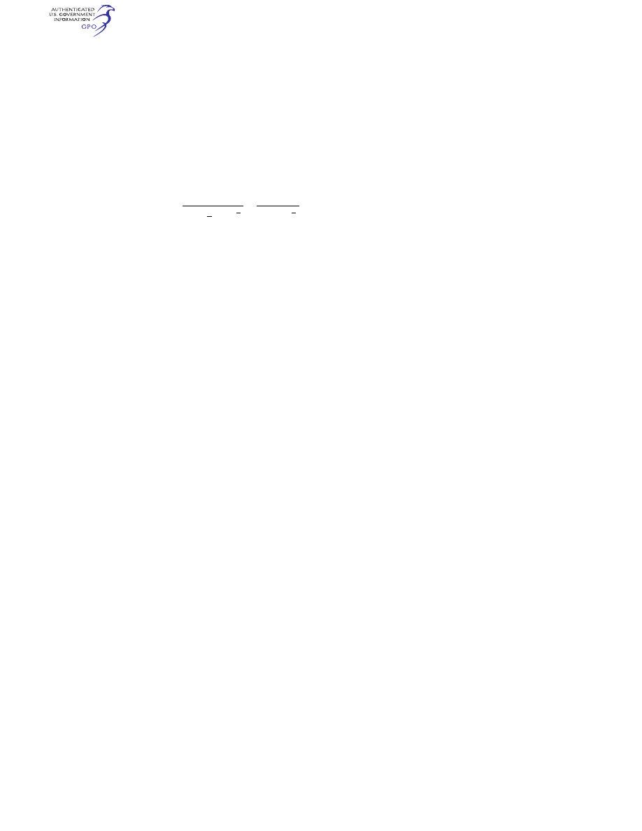
n
C V
W
K
r
w
S
x
=
⎛
⎝
⎞
⎠
×
+
(
)
1
0
1
2
2
2
3
1
3
2
3
1
Tan
β
(b) The following values are used:
(1)
n
W
= water reaction load factor
(that is, the water reaction divided by
seaplane weight).
(2)
C
1
= empirical seaplane operations
factor equal to 0.012 (except that this
factor may not be less than that nec-
essary to obtain the minimum value of
step load factor of 2.33).
(3)
V
S0
= seaplane stalling speed in
knots with flaps extended in the appro-
priate landing position and with no
slipstream effect.
(4)
b
= angle of dead rise at the longi-
tudinal station at which the load fac-
tor is being determined in accordance
with figure 1 of appendix B.
(5)
W=
seaplane design landing
weight in pounds.
(6)
K
1
= empirical hull station weigh-
ing factor, in accordance with figure 2
of appendix B.
(7)
r
x
= ratio of distance, measured
parallel to hull reference axis, from the
center of gravity of the seaplane to the
hull longitudinal station at which the
load factor is being computed to the ra-
dius of gyration in pitch of the sea-
plane, the hull reference axis being a
straight line, in the plane of sym-
metry, tangential to the keel at the
main step.
(c) For a twin float seaplane, because
of the effect of flexibility of the attach-
ment of the floats to the seaplane, the
factor
K
1
may be reduced at the bow
and stern to 0.8 of the value shown in
figure 2 of appendix B. This reduction
applies only to the design of the carry-
through and seaplane structure.
[Doc. No. 5066, 29 FR 18291, Dec. 24, 1964, as
amended by Amdt. 25–23, 35 FR 5673, Apr. 8,
1970]
§ 25.529
Hull and main float landing
conditions.
(a)
Symmetrical step, bow, and stern
landing. For symmetrical step, bow,
and stern landings, the limit water re-
action load factors are those computed
under § 25.527. In addition—
(1) For symmetrical step landings,
the resultant water load must be ap-
plied at the keel, through the center of
gravity, and must be directed per-
pendicularly to the keel line;
(2) For symmetrical bow landings,
the resultant water load must be ap-
plied at the keel, one-fifth of the longi-
tudinal distance from the bow to the
step, and must be directed perpendicu-
larly to the keel line; and
(3) For symmetrical stern landings,
the resultant water load must be ap-
plied at the keel, at a point 85 percent
of the longitudinal distance from the
step to the stern post, and must be di-
rected perpendicularly to the keel line.
(b)
Unsymmetrical landing for hull and
single float seaplanes. Unsymmetrical
step, bow, and stern landing conditions
must be investigated. In addition—
(1) The loading for each condition
consists of an upward component and a
side component equal, respectively, to
0.75 and 0.25 tan
b
times the resultant
load in the corresponding symmetrical
landing condition; and
(2) The point of application and di-
rection of the upward component of the
load is the same as that in the sym-
metrical condition, and the point of ap-
plication of the side component is at
the same longitudinal station as the
upward component but is directed in-
ward perpendicularly to the plane of
symmetry at a point midway between
the keel and chine lines.
(c)
Unsymmetrical landing; twin float
seaplanes. The unsymmetrical loading
consists of an upward load at the step
of each float of 0.75 and a side load of
0.25 tan
b
at one float times the step
landing load reached under § 25.527. The
side load is directed inboard, per-
pendicularly to the plane of symmetry
midway between the keel and chine
lines of the float, at the same longitu-
dinal station as the upward load.
§ 25.531
Hull and main float takeoff
condition.
For the wing and its attachment to
the hull or main float—
(a) The aerodynamic wing lift is as-
sumed to be zero; and
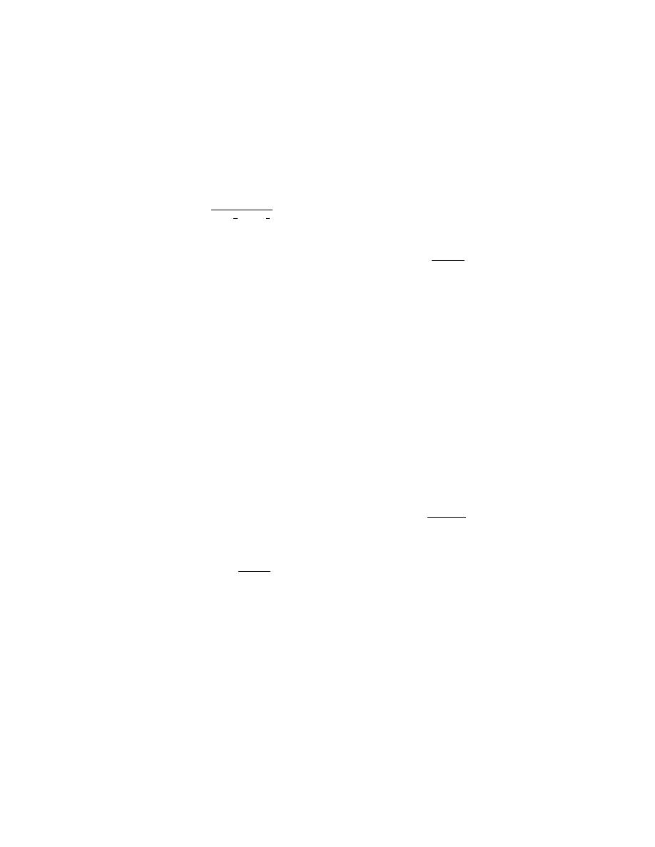
(b) A downward inertia load, cor-
responding to a load factor computed
from the following formula, must be
applied:
VerDate Sep<11>2014
09:06 Jun 28, 2024
Jkt 262046
PO 00000
Frm 00266
Fmt 8010
Sfmt 8010
Y:\SGML\262046.XXX
262046
EC28SE91.037</MATH>
jspears on DSK121TN23PROD with CFR