background image

258 

14 CFR Ch. I (1–1–24 Edition) 

§ 25.535 

These pressures are uniform and must 
be applied simultaneously over the en-
tire hull or main float bottom. The 
loads obtained must be carried into the 
sidewall structure of the hull proper, 
but need not be transmitted in a fore 
and aft direction as shear and bending 
loads. 

[Doc. No. 5066, 29 FR 18291, Dec. 24, 1964, as 
amended by Amdt. 25–23, 35 FR 5673, Apr. 8, 
1970] 

§ 25.535

Auxiliary float loads. 

(a) 

General. Auxiliary floats and their 

attachments and supporting structures 
must be designed for the conditions 
prescribed in this section. In the cases 
specified in paragraphs (b) through (e) 
of this section, the prescribed water 
loads may be distributed over the float 
bottom to avoid excessive local loads, 
using bottom pressures not less than 
those prescribed in paragraph (g) of 
this section. 

(b) 

Step loading. The resultant water 

load must be applied in the plane of 
symmetry of the float at a point three- 
fourths of the distance from the bow to 
the step and must be perpendicular to 
the keel. The resultant limit load is 
computed as follows, except that the 
value of 

L  need not exceed three times 

the weight of the displaced water when 
the float is completely submerged: 

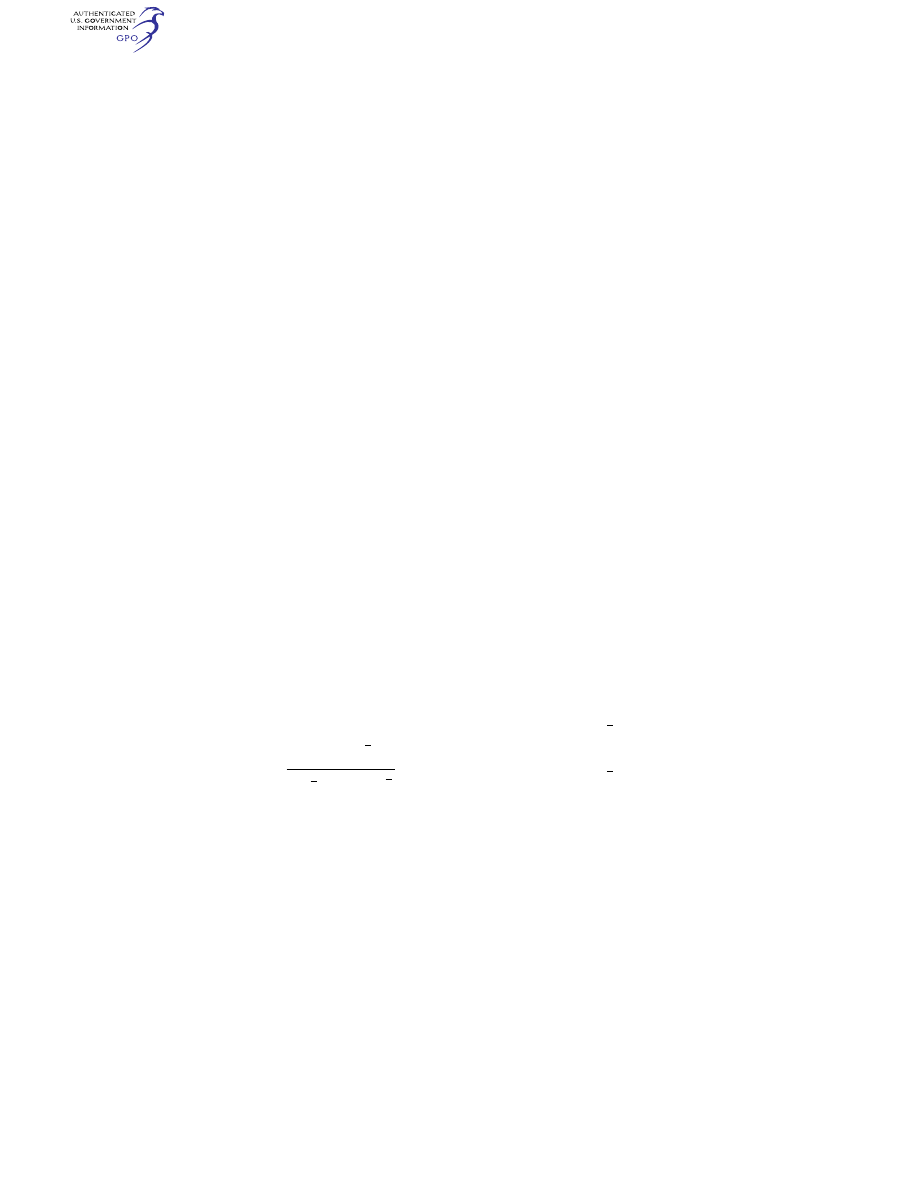
L

C V

W

r

S

s

y

=

+

(

)

5

2

0

2

2
3

2
3

2
3

1

tan

β

where— 

= limit load (lbs.); 
C

5

= 0.0053; 

V

S0

= seaplane stalling speed (knots) with 

landing flaps extended in the appropriate 
position and with no slipstream effect; 

W  = seaplane design landing weight in 

pounds; 

b

S

= angle of dead rise at a station 

3

4

of the 

distance from the bow to the step, but 
need not be less than 15 degrees; and 

r

y

= ratio of the lateral distance between the 

center of gravity and the plane of sym-
metry of the float to the radius of gyra-
tion in roll. 

(c) 

Bow loading. The resultant limit 

load must be applied in the plane of 
symmetry of the float at a point one- 
fourth of the distance from the bow to 
the step and must be perpendicular to 

the tangent to the keel line at that 
point. The magnitude of the resultant 
load is that specified in paragraph (b) 
of this section. 

(d) 

Unsymmetrical step loading. The re-

sultant water load consists of a compo-
nent equal to 0.75 times the load speci-
fied in paragraph (a) of this section and 
a side component equal to 0.25 tan 

times the load specified in paragraph 
(b) of this section. The side load must 
be applied perpendicularly to the plane 
of symmetry of the float at a point 
midway between the keel and the 
chine. 

(e) 

Unsymmetrical bow loading. The re-

sultant water load consists of a compo-
nent equal to 0.75 times the load speci-
fied in paragraph (b) of this section and 
a side component equal to 0.25 tan 

times the load specified in paragraph 
(c) of this section. The side load must 
be applied perpendicularly to the plane 
of symmetry at a point midway be-
tween the keel and the chine. 

(f) 

Immersed float condition. The re-

sultant load must be applied at the 
centroid of the cross section of the 
float at a point one-third of the dis-
tance from the bow to the step. The 
limit load components are as follows: 

vertical

aft

side

=

=

=

ρ

ρ

ρ

g

x

y

V

C

V

KV

C V

KV

S

S

2

2

2

2

2
3

0

2
3

0

where— 

= mass density of water (slugs/ft.

2

); 

= volume of float (ft.

2

); 

C

x

= coefficient of drag force, equal to 0.133; 

C

y

= coefficient of side force, equal to 0.106; 

= 0.8, except that lower values may be used 

if it is shown that the floats are incapa-
ble of submerging at a speed of 0.8 

V

S0

in 

normal operations; 

V

S0

= seaplane stalling speed (knots) with 

landing flaps extended in the appropriate 
position and with no slipstream effect; 
and 

= acceleration due to gravity (ft./sec.

2

). 

(g) 

Float bottom pressures. The float 

bottom pressures must be established 
under § 25.533, except that the value of 
K

2

in the formulae may be taken as 1.0. 

The angle of dead rise to be used in de-
termining the float bottom pressures is 

VerDate Sep<11>2014 

09:06 Jun 28, 2024

Jkt 262046

PO 00000

Frm 00268

Fmt 8010

Sfmt 8010

Y:\SGML\262046.XXX

262046

EC28SE91.042</MATH>

EC28SE91.043</MATH>

jspears on DSK121TN23PROD with CFR

background image

259 

Federal Aviation Administration, DOT 

§ 25.562 

set forth in paragraph (b) of this sec-
tion. 

[Doc. No. 5066, 29 FR 18291, Dec. 24, 1964, as 
amended by Amdt. 25–23, 35 FR 5673, Apr. 8, 
1970; Amdt. 25–148, 87 FR 75710, Dec. 9, 2022; 88 
FR 2813, Jan. 18, 2023] 

§ 25.537

Seawing loads. 

Seawing design loads must be based 

on applicable test data. 

E

MERGENCY

L

ANDING

C

ONDITIONS


§ 25.561

General. 

(a) The airplane, although it may be 

damaged in emergency landing condi-
tions on land or water, must be de-
signed as prescribed in this section to 
protect each occupant under those con-
ditions. 

(b) The structure must be designed to 

give each occupant every reasonable 
chance of escaping serious injury in a 
minor crash landing when— 

(1) Proper use is made of seats, belts, 

and all other safety design provisions; 

(2) The wheels are retracted (where 

applicable); and 

(3) The occupant experiences the fol-

lowing ultimate inertia forces acting 
separately relative to the surrounding 
structure: 

(i) Upward, 3.0g 
(ii) Forward, 9.0g 
(iii) Sideward, 3.0g on the airframe; 

and 4.0g on the seats and their attach-
ments. 

(iv) Downward, 6.0g 
(v) Rearward, 1.5g 
(c) For equipment, cargo in the pas-

senger compartments and any other 
large masses, the following apply: 

(1) Except as provided in paragraph 

(c)(2) of this section, these items must 
be positioned so that if they break 
loose they will be unlikely to: 

(i) Cause direct injury to occupants; 
(ii) Penetrate fuel tanks or lines or 

cause fire or explosion hazard by dam-
age to adjacent systems; or 

(iii) Nullify any of the escape facili-

ties provided for use after an emer-
gency landing. 

(2) When such positioning is not prac-

tical (e.g. fuselage mounted engines or 
auxiliary power units) each such item 
of mass shall be restrained under all 
loads up to those specified in paragraph 
(b)(3) of this section. The local attach-

ments for these items should be de-
signed to withstand 1.33 times the spec-
ified loads if these items are subject to 
severe wear and tear through frequent 
removal (e.g. quick change interior 
items). 

(d) Seats and items of mass (and 

their supporting structure) must not 
deform under any loads up to those 
specified in paragraph (b)(3) of this sec-
tion in any manner that would impede 
subsequent rapid evacuation of occu-
pants. 

[Doc. No. 5066, 29 FR 18291, Dec. 24, 1964, as 
amended by Amdt. 25–23, 35 FR 5673, Apr. 8, 
1970; Amdt. 25–64, 53 FR 17646, May 17, 1988; 
Amdt. 25–91, 62 FR 40706, July 29, 1997] 

§ 25.562

Emergency landing dynamic 

conditions. 

(a) The seat and restraint system in 

the airplane must be designed as pre-
scribed in this section to protect each 
occupant during an emergency landing 
condition when— 

(1) Proper use is made of seats, safety 

belts, and shoulder harnesses provided 
for in the design; and 

(2) The occupant is exposed to loads 

resulting from the conditions pre-
scribed in this section. 

(b) Each seat type design approved 

for crew or passenger occupancy during 
takeoff and landing must successfully 
complete dynamic tests or be dem-
onstrated by rational analysis based on 
dynamic tests of a similar type seat, in 
accordance with each of the following 
emergency landing conditions. The 
tests must be conducted with an occu-
pant simulated by a 170-pound 
anthropomorphic test dummy, as de-
fined by 49 CFR Part 572, Subpart B, or 
its equivalent, sitting in the normal 
upright position. 

(1) A change in downward vertical ve-

locity (

v) of not less than 35 feet per 

second, with the airplane’s longitu-
dinal axis canted downward 30 degrees 
with respect to the horizontal plane 
and with the wings level. Peak floor de-
celeration must occur in not more than 
0.08 seconds after impact and must 
reach a minimum of 14g. 

(2) A change in forward longitudinal 

velocity (

v) of not less than 44 feet 

per second, with the airplane’s longitu-
dinal axis horizontal and yawed 10 de-
grees either right or left, whichever 

VerDate Sep<11>2014 

09:06 Jun 28, 2024

Jkt 262046

PO 00000

Frm 00269

Fmt 8010

Sfmt 8010

Y:\SGML\262046.XXX

262046

jspears on DSK121TN23PROD with CFR