
554
14 CFR Ch. I (1–1–24 Edition)
§ 27.1387
§ 27.1387
Position light system dihe-
dral angles.
(a) Except as provided in paragraph
(e) of this section, each forward and
rear position light must, as installed,
show unbroken light within the dihe-
dral angles described in this section.
(b) Dihedral angle
L (left) is formed
by two intersecting vertical planes, the
first parallel to the longitudinal axis of
the rotorcraft, and the other at 110 de-
grees to the left of the first, as viewed
when looking forward along the longi-
tudinal axis.
(c) Dihedral angle
R (right) is formed
by two intersecting vertical planes, the
first parallel to the longitudinal axis of
the rotorcraft, and the other at 110 de-
grees to the right of the first, as viewed
when looking forward along the longi-
tudinal axis.
(d) Dihedral angle
A (aft) is formed
by two intersecting vertical planes
making angles of 70 degrees to the
right and to the left, respectively, to a
vertical plane passing through the lon-
gitudinal axis, as viewed when looking
aft along the longitudinal axis.
(e) If the rear position light, when
mounted as far aft as practicable in ac-
cordance with § 25.1385(c), cannot show
unbroken light within dihedral angle A
(as defined in paragraph (d) of this sec-
tion), a solid angle or angles of ob-
structed visibility totaling not more
than 0.04 steradians is allowable within
that dihedral angle, if such solid angle
is within a cone whose apex is at the
rear position light and whose elements
make an angle of 30
°
with a vertical
line passing through the rear position
light.
(49 U.S.C. 1655(c))
[Doc. No. 5074, 29 FR 15695, Nov. 24, 1964, as
amended by Amdt. 27–7, 36 FR 21278, Nov. 5,
1971]
§ 27.1389
Position light distribution
and intensities.
(a)
General. the intensities prescribed
in this section must be provided by new
equipment with light covers and color
filters in place. Intensities must be de-
termined with the light source oper-
ating at a steady value equal to the av-
erage luminous output of the source at
the normal operating voltage of the
rotorcraft. The light distribution and
intensity of each position light must
meet the requirements of paragraph (b)
of this section.
(b)
Forward and rear position lights.
The light distribution and intensities
of forward and rear position lights
must be expressed in terms of min-
imum intensities in the horizontal
plane, minimum intensities in any
vertical plane, and maximum inten-
sities in overlapping beams, within di-
hedral angles
L, R, and A, and must
meet the following requirements:
(1)
Intensities in the horizontal plane.
Each intensity in the horizontal plane
(the plane containing the longitudinal
axis of the rotorcraft and perpendicular
to the plane of symmetry of the rotor-
craft) must equal or exceed the values
in § 27.1391.
(2)
Intensities in any vertical plane.
Each intensity in any vertical plane
(the plane perpendicular to the hori-
zontal plane) must equal or exceed the
appropriate value in § 27.1393, where
I is
the minimum intensity prescribed in
§ 27.1391 for the corresponding angles in
the horizontal plane.
(3)
Intensities in overlaps between adja-
cent signals. No intensity in any over-
lap between adjacent signals may ex-
ceed the values in § 27.1395, except that
higher intensities in overlaps may be
used with main beam intensities sub-
stantially greater than the minima
specified in §§ 27.1391 and 27.1393, if the
overlap intensities in relation to the
main beam intensities do not adversely
affect signal clarity. When the peak in-
tensity of the forward position lights is
greater than 100 candles, the maximum
overlap intensities between them may
exceed the values in § 27.1395 if the
overlap intensity in Area A is not more
than 10 percent of peak position light
intensity and the overlap intensity in
Area B is not more than 2.5 percent of
peak position light intensity.
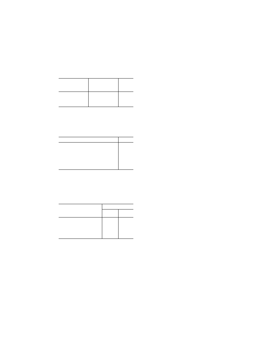
§ 27.1391
Minimum intensities in the
horizontal plane of forward and
rear position lights.
Each position light intensity must
equal or exceed the applicable values in
the following table:
VerDate Sep<11>2014
09:06 Jun 28, 2024
Jkt 262046
PO 00000
Frm 00564
Fmt 8010
Sfmt 8010
Y:\SGML\262046.XXX
262046
jspears on DSK121TN23PROD with CFR
555
Federal Aviation Administration, DOT
§ 27.1401
Dihedral angle (light in-
cluded)
Angle from right or left
of longitudinal axis,
measured from dead
ahead
Intensity
(candles)
L and R (forward red
and green).
10
°
to 10
°
...................
10
°
to 20
°
...................
20
°
to 110
°
.................
40
30
5
A (rear white) ..............
110
°
to 180
°
...............
20
§ 27.1393
Minimum intensities in any
vertical plane of forward and rear
position lights.
Each position light intensity must
equal or exceed the applicable values in
the following table:
Angle above or below the horizontal plane
Intensity, l
0
°
.........................................................................
1.00
0
°
to 5
°
................................................................
0.90
5
°
to 10
°
..............................................................
0.80
10
°
to 15
°
............................................................
0.70
15
°
to 20
°
............................................................
0.50
20
°
to 30
°
............................................................
0.30
30
°
to 40
°
............................................................
0.10
40
°
to 90
°
............................................................
0.05
§ 27.1395
Maximum intensities in over-
lapping beams of forward and rear
position lights.
No position light intensity may ex-
ceed the applicable values in the fol-
lowing table, except as provided in
§ 27.1389(b)(3).
Overlaps
Maximum Intensity
Area A
(candles)
Area B
(candles)
Green in dihedral angle L .............
10 1
Red in dihedral angle R ................
10 1
Green in dihedral angle A .............
5 1
Red in dihedral angle A ................
5 1
Rear white in dihedral angle L ......
5 1
Rear white in dihedral angle R .....
5 1
Where—
(a) Area A includes all directions in
the adjacent dihedral angle that pass
through the light source and intersect
the common boundary plane at more
than 10 degrees but less than 20 de-
grees, and
(b) Area B includes all directions in
the adjacent dihedral angle that pass
through the light source and intersect
the common boundary plane at more
than 20 degrees.
§ 27.1397
Color specifications.
Each position light color must have
the applicable International Commis-
sion on Illumination chromaticity co-
ordinates as follows:
(a)
Aviation red—
y is not greater than 0.335; and
z is not greater than 0.002.
(b)
Aviation green—
x is not greater than 0.440
¥
0.320
y;
x is not greater than y
¥
0.170; and
y is not less than 0.390
¥
0.170
x.
(c)
Aviation white—
x is not less than 0.300 and not greater than
0.540;
y is not less than x
¥
0.040’’ or
y
c
¥
0.010,
whichever is the smaller; and
y is not greater than x + 0.020 nor
0.636
¥
0.400
x;
Where
y
c
is the
y coordinate of the Planck-
ian radiator for the value of
x considered.
[Doc. No. 5074, 29 FR 15695, Nov. 24, 1964, as
amended by Amdt. 27–6, 36 FR 12972, July 10,
1971]
§ 27.1399
Riding light.
(a) Each riding light required for
water operation must be installed so
that it can—
(1) Show a white light for at least
two nautical miles at night under clear
atmospheric conditions; and
(2) Show a maximum practicable un-
broken light with the rotorcraft on the
water.
(b) Externally hung lights may be
used.
[Doc. No. 5074, 29 FR 15695, Nov. 24, 1964, as
amended by Amdt. 27–2, 33 FR 964, Jan. 26,
1968]
§ 27.1401
Anticollision light system.
(a)
General. If certification for night
operation is requested, the rotorcraft
must have an anticollision light sys-
tem that—
(1) Consists of one or more approved
anticollision lights located so that
their emitted light will not impair the
crew’s vision or detract from the con-
spicuity of the position lights; and
(2) Meets the requirements of para-
graphs (b) through (f) of this section.
(b)
Field of coverage. The system must
consist of enough lights to illuminate
the vital areas around the rotorcraft,
considering the physical configuration
and flight characteristics of the rotor-
craft. The field of coverage must ex-
tend in each direction within at least
30 degrees below the horizontal plane of
the rotorcraft, except that there may
VerDate Sep<11>2014
09:06 Jun 28, 2024
Jkt 262046
PO 00000
Frm 00565
Fmt 8010
Sfmt 8010
Y:\SGML\262046.XXX
262046
jspears on DSK121TN23PROD with CFR