
572
14 CFR Ch. I (1–1–24 Edition)
Pt. 29
kHz, increasing 20 decibels (dB) per fre-
quency decade to a minimum of 30 mA at 500
kHz.
(2) From 500 kHz to 40 MHz, the conducted
susceptibility current must be at least 30
mA.
(3) From 40 MHz to 400 MHz, use conducted
susceptibility tests, starting at a minimum
of 30 mA at 40 MHz, decreasing 20 dB per fre-
quency decade to a minimum of 3 mA at 400
MHz.
(4) From 100 MHz to 400 MHz, use radiated
susceptibility tests at a minimum of 20 volts
per meter (V/m) peak with CW and 1 kHz
square wave modulation with 90 percent
depth or greater.
(5) From 400 MHz to 8 gigahertz (GHz), use
radiated susceptibility tests at a minimum
of 150 V/m peak with pulse modulation of 4
percent duty cycle with a 1 kHz pulse repeti-
tion frequency. This signal must be switched
on and off at a rate of 1 Hz with a duty cycle
of 50 percent.
(e)
Equipment HIRF Test Level 2. Equipment
HIRF test level 2 is HIRF environment II in
table II of this appendix reduced by accept-
able aircraft transfer function and attenu-
ation curves. Testing must cover the fre-
quency band of 10 kHz to 8 GHz.
(f)
Equipment HIRF Test Level 3. (1) From 10
kHz to 400 MHz, use conducted susceptibility
tests, starting at a minimum of 0.15 mA at 10
kHz, increasing 20 dB per frequency decade
to a minimum of 7.5 mA at 500 kHz.
(2) From 500 kHz to 40 MHz, use conducted
susceptibility tests at a minimum of 7.5 mA.
(3) From 40 MHz to 400 MHz, use conducted
susceptibility tests, starting at a minimum
of 7.5 mA at 40 MHz, decreasing 20 dB per fre-
quency decade to a minimum of 0.75 mA at
400 MHz.
(4) From 100 MHz to 8 GHz, use radiated
susceptibility tests at a minimum of 5 V/m.
[Doc. No. FAA–2006–23657, 72 FR 44027, Aug. 6,
2007]
PART 29—AIRWORTHINESS STAND-
ARDS: TRANSPORT CATEGORY
ROTORCRAFT
Subpart A—General
Sec.
29.1
Applicability.
29.2
Special retroactive requirements.
Subpart B—Flight
G
ENERAL
29.21
Proof of compliance.
29.25
Weight limits.
29.27
Center of gravity limits.
29.29
Empty weight and corresponding cen-
ter of gravity.
29.31
Removable ballast.
29.33
Main rotor speed and pitch limits.
P
ERFORMANCE
29.45
General.
29.49
Performance at minimum operating
speed.
29.51
Takeoff data: general.
29.53
Takeoff: Category A.
29.55
Takeoff decision point (TDP): Cat-
egory A.
29.59
Takeoff path: Category A.
29.60
Elevated heliport takeoff path: Cat-
egory A.
29.61
Takeoff distance: Category A.
29.62
Rejected takeoff: Category A.
29.63
Takeoff: Category B.
29.64
Climb: General.
29.65
Climb: All engines operating.
29.67
Climb: One engine inoperative (OEI).
29.71
Helicopter angle of glide: Category B.
29.75
Landing: General.
29.77
Landing Decision Point (LDP): Cat-
egory A.
29.79
Landing: Category A.
29.81
Landing distance: Category A.
29.83
Landing: Category B.
29.85
Balked landing: Category A.
29.87
Height-velocity envelope.
F
LIGHT
C
HARACTERISTICS
29.141
General.
29.143
Controllability and maneuverability.
29.151
Flight controls.
29.161
Trim control.
29.171
Stability: general.
29.173
Static longitudinal stability.
29.175
Demonstration of static longitudinal
stability.
29.177
Static directional stability.
29.181
Dynamic stability: Category A rotor-
craft.
G
ROUND AND
W
ATER
H
ANDLING
C
HARACTERISTICS
29.231
General.
29.235
Taxiing condition.
29.239
Spray characteristics.
29.241
Ground resonance.
M
ISCELLANEOUS
F
LIGHT
R
EQUIREMENTS
29.251
Vibration.
Subpart C—Strength Requirements
G
ENERAL
29.301
Loads.
29.303
Factor of safety.
29.305
Strength and deformation.
29.307
Proof of structure.
29.309
Design limitations.
F
LIGHT
L
OADS
29.321
General.
29.337
Limit maneuvering load factor.
29.339
Resultant limit maneuvering loads.
VerDate Sep<11>2014
09:06 Jun 28, 2024
Jkt 262046
PO 00000
Frm 00582
Fmt 8010
Sfmt 8010
Y:\SGML\262046.XXX
262046
jspears on DSK121TN23PROD with CFR

573
Federal Aviation Administration, DOT
Pt. 29
29.341
Gust loads.
29.351
Yawing conditions.
29.361
Engine torque.
C
ONTROL
S
URFACE AND
S
YSTEM
L
OADS
29.391
General.
29.395
Control system.
29.397
Limit pilot forces and torques.
29.399
Dual control system.
29.411
Ground clearance: tail rotor guard.
29.427
Unsymmetrical loads.
G
ROUND
L
OADS
29.471
General.
29.473
Ground loading conditions and as-
sumptions.
29.475
Tires and shock absorbers.
29.477
Landing gear arrangement.
29.479
Level landing conditions.
29.481
Tail-down landing conditions.
29.483
One-wheel landing conditions.
29.485
Lateral drift landing conditions.
29.493
Braked roll conditions.
29.497
Ground loading conditions: landing
gear with tail wheels.
29.501
Ground loading conditions: landing
gear with skids.
29.505
Ski landing conditions.
29.511
Ground load: unsymmetrical loads on
multiple-wheel units.
W
ATER
L
OADS
29.519
Hull type rotorcraft: Water-based and
amphibian.
29.521
Float landing conditions.
M
AIN
C
OMPONENT
R
EQUIREMENTS
29.547
Main and tail rotor structure.
29.549
Fuselage and rotor pylon structures.
29.551
Auxiliary lifting surfaces.
E
MERGENCY
L
ANDING
C
ONDITIONS
29.561
General.
29.562
Emergency landing dynamic condi-
tions.
29.563
Structural ditching provisions.
F
ATIGUE
E
VALUATION
29.571
Fatigue tolerance evaluation of me-
tallic structure.
29.573
Damage tolerance and fatigue evalua-
tion of composite rotorcraft structures.
Subpart D—Design and Construction
G
ENERAL
29.601
Design.
29.602
Critical parts.
29.603
Materials.
29.605
Fabrication methods.
29.607
Fasteners.
29.609
Protection of structure.
29.610
Lightning and static electricity pro-
tection.
29.611
Inspection provisions.
29.613
Material strength properties and de-
sign values.
29.619
Special factors.
29.621
Casting factors.
29.623
Bearing factors.
29.625
Fitting factors.
29.629
Flutter and divergence.
29.631
Bird strike.
R
OTORS
29.653
Pressure venting and drainage of
rotor blades.
29.659
Mass balance.
29.661
Rotor blade clearance.
29.663
Ground resonance prevention means.
C
ONTROL
S
YSTEMS
29.671
General.
29.672
Stability augmentation, automatic,
and power-operated systems.
29.673
Primary flight controls.
29.674
Interconnected controls.
29.675
Stops.
29.679
Control system locks.
29.681
Limit load static tests.
29.683
Operation tests.
29.685
Control system details.
29.687
Spring devices.
29.691
Autorotation control mechanism.
29.695
Power boost and power-operated con-
trol system.
L
ANDING
G
EAR
29.723
Shock absorption tests.
29.725
Limit drop test.
29.727
Reserve energy absorption drop test.
29.729
Retracting mechanism.
29.731
Wheels.
29.733
Tires.
29.735
Brakes.
29.737
Skis.
F
LOATS AND
H
ULLS
29.751
Main float buoyancy.
29.753
Main float design.
29.755
Hull buoyancy.
29.757
Hull and auxiliary float strength.
P
ERSONNEL AND
C
ARGO
A
CCOMMODATIONS
29.771
Pilot compartment.
29.773
Pilot compartment view.
29.775
Windshields and windows.
29.777
Cockpit controls.
29.779
Motion and effect of cockpit controls.
29.783
Doors.
29.785
Seats, berths, litters, safety belts,
and harnesses.
29.787
Cargo and baggage compartments.
29.801
Ditching.
29.803
Emergency evacuation.
29.805
Flight crew emergency exits.
29.807
Passenger emergency exits.
29.809
Emergency exit arrangement.
29.811
Emergency exit marking.
29.812
Emergency lighting.
29.813
Emergency exit access.
VerDate Sep<11>2014
09:06 Jun 28, 2024
Jkt 262046
PO 00000
Frm 00583
Fmt 8010
Sfmt 8010
Y:\SGML\262046.XXX
262046
jspears on DSK121TN23PROD with CFR

574
14 CFR Ch. I (1–1–24 Edition)
Pt. 29
29.815
Main aisle width.
29.831
Ventilation.
29.833
Heaters.
F
IRE
P
ROTECTION
29.851
Fire extinguishers.
29.853
Compartment interiors.
29.855
Cargo and baggage compartments.
29.859
Combustion heater fire protection.
29.861
Fire protection of structure, controls,
and other parts.
29.863
Flammable fluid fire protection.
E
XTERNAL
L
OADS
29.865
External loads.
M
ISCELLANEOUS
29.871
Leveling marks.
29.873
Ballast provisions.
Subpart E—Powerplant
G
ENERAL
29.901
Installation.
29.903
Engines.
29.907
Engine vibration.
29.908
Cooling fans.
R
OTOR
D
RIVE
S
YSTEM
29.917
Design.
29.921
Rotor brake.
29.923
Rotor drive system and control mech-
anism tests.
29.927
Additional tests.
29.931
Shafting critical speed.
29.935
Shafting joints.
29.939
Turbine engine operating characteris-
tics.
F
UEL
S
YSTEM
29.951
General.
29.952
Fuel system crash resistance.
29.953
Fuel system independence.
29.954
Fuel system lightning protection.
29.955
Fuel flow.
29.957
Flow between interconnected tanks.
29.959
Unusable fuel supply.
29.961
Fuel system hot weather operation.
29.963
Fuel tanks: general.
29.965
Fuel tank tests.
29.967
Fuel tank installation.
29.969
Fuel tank expansion space.
29.971
Fuel tank sump.
29.973
Fuel tank filler connection.
29.975
Fuel tank vents and carburetor vapor
vents.
29.977
Fuel tank outlet.
29.979
Pressure refueling and fueling provi-
sions below fuel level.
F
UEL
S
YSTEM
C
OMPONENTS
29.991
Fuel pumps.
29.993
Fuel system lines and fittings.
29.995
Fuel valves.
29.997
Fuel strainer or filter.
29.999
Fuel system drains.
29.1001
Fuel jettisoning.
O
IL
S
YSTEM
29.1011
Engines: general.
29.1013
Oil tanks.
29.1015
Oil tank tests.
29.1017
Oil lines and fittings.
29.1019
Oil strainer or filter.
29.1021
Oil system drains.
29.1023
Oil radiators.
29.1025
Oil valves.
29.1027
Transmission and gearboxes: gen-
eral.
C
OOLING
29.1041
General.
29.1043
Cooling tests.
29.1045
Climb cooling test procedures.
29.1047
Takeoff cooling test procedures.
29.1049
Hovering cooling test procedures.
I
NDUCTION
S
YSTEM
29.1091
Air induction.
29.1093
Induction system icing protection.
29.1101
Carburetor air preheater design.
29.1103
Induction systems ducts and air duct
systems.
29.1105
Induction system screens.
29.1107
Inter-coolers and after-coolers.
29.1109
Carburetor air cooling.
E
XHAUST
S
YSTEM
29.1121
General.
29.1123
Exhaust piping.
29.1125
Exhaust heat exchangers.
P
OWERPLANT
C
ONTROLS AND
A
CCESSORIES
29.1141
Powerplant controls: general.
29.1142
Auxiliary power unit controls.
29.1143
Engine controls.
29.1145
Ignition switches.
29.1147
Mixture controls.
29.1151
Rotor brake controls.
29.1157
Carburetor air temperature controls.
29.1159
Supercharger controls.
29.1163
Powerplant accessories.
29.1165
Engine ignition systems.
P
OWERPLANT
F
IRE
P
ROTECTION
29.1181
Designated fire zones: regions in-
cluded.
29.1183
Lines, fittings, and components.
29.1185
Flammable fluids.
29.1187
Drainage and ventilation of fire
zones.
29.1189
Shutoff means.
29.1191
Firewalls.
29.1193
Cowling and engine compartment
covering.
29.1194
Other surfaces.
29.1195
Fire extinguishing systems.
29.1197
Fire extinguishing agents.
29.1199
Extinguishing agent containers.
29.1201
Fire extinguishing system materials.
VerDate Sep<11>2014
09:06 Jun 28, 2024
Jkt 262046
PO 00000
Frm 00584
Fmt 8010
Sfmt 8010
Y:\SGML\262046.XXX
262046
jspears on DSK121TN23PROD with CFR

575
Federal Aviation Administration, DOT
Pt. 29
29.1203
Fire detector systems.
Subpart F—Equipment
G
ENERAL
29.1301
Function and installation.
29.1303
Flight and navigation instruments.
29.1305
Powerplant instruments.
29.1307
Miscellaneous equipment.
29.1309
Equipment, systems, and installa-
tions.
29.1316
Electrical and electronic system
lightning protection.
29.1317
High-intensity Radiated Fields
(HIRF) Protection.
I
NSTRUMENTS
: I
NSTALLATION
29.1321
Arrangement and visibility.
29.1322
Warning, caution, and advisory
lights.
29.1323
Airspeed indicating system.
29.1325
Static pressure and pressure altim-
eter systems.
29.1327
Magnetic direction indicator.
29.1329
Automatic pilot and flight guidance
system.
29.1331
Instruments using a power supply.
29.1333
Instrument systems.
29.1337
Powerplant instruments.
E
LECTRICAL
S
YSTEMS AND
E
QUIPMENT
29.1351
General.
29.1353
Energy storage systems.
29.1355
Distribution system.
29.1357
Circuit protective devices.
29.1359
Electrical system fire and smoke
protection.
29.1363
Electrical system tests.
L
IGHTS
29.1381
Instrument lights.
29.1383
Landing lights.
29.1385
Position light system installation.
29.1387
Position light system dihedral an-
gles.
29.1389
Position light distribution and in-
tensities.
29.1391
Minimum intensities in the hori-
zontal plane of forward and rear position
lights.
29.1393
Minimum intensities in any vertical
plane of forward and rear position lights.
29.1395
Maximum intensities in overlapping
beams of forward and rear position
lights.
29.1397
Color specifications.
29.1399
Riding light.
29.1401
Anticollision light system.
S
AFETY
E
QUIPMENT
29.1411
General.
29.1413
Safety belts: passenger warning de-
vice.
29.1415
Ditching equipment.
29.1419
Ice protection.
M
ISCELLANEOUS
E
QUIPMENT
29.1431
Electronic equipment.
29.1433
Vacuum systems.
29.1435
Hydraulic systems.
29.1439
Protective breathing equipment.
29.1457
Cockpit voice recorders.
29.1459
Flight data recorders.
29.1461
Equipment containing high energy
rotors.
Subpart G—Operating Limitations and
Information
29.1501
General.
O
PERATING
L
IMITATIONS
29.1503
Airspeed limitations: general.
29.1505
Never-exceed speed.
29.1509
Rotor speed.
29.1517
Limiting height-velocity envelope.
29.1519
Weight and center of gravity.
29.1521
Powerplant limitations.
29.1522
Auxiliary power unit limitations.
29.1523
Minimum flight crew.
29.1525
Kinds of operations.
29.1527
Maximum operating altitude.
29.1529
Instructions for Continued Air-
worthiness.
M
ARKINGS AND
P
LACARDS
29.1541
General.
29.1543
Instrument markings: general.
29.1545
Airspeed indicator.
29.1547
Magnetic direction indicator.
29.1549
Powerplant instruments.
29.1551
Oil quantity indicator.
29.1553
Fuel quantity indicator.
29.1555
Control markings.
29.1557
Miscellaneous markings and plac-
ards.
29.1559
Limitations placard.
29.1561
Safety equipment.
29.1565
Tail rotor.
R
OTORCRAFT
F
LIGHT
M
ANUAL
29.1581
General.
29.1583
Operating limitations.
29.1585
Operating procedures.
29.1587
Performance information.
29.1589
Loading information.
A
PPENDIX
A
TO
P
ART
29—I
NSTRUCTIONS FOR
C
ONTINUED
A
IRWORTHINESS
A
PPENDIX
B
TO
P
ART
29—A
IRWORTHINESS
C
RI
-
TERIA
FOR
H
ELICOPTER
I
NSTRUMENT
F
LIGHT
A
PPENDIX
C
TO
P
ART
29—I
CING
C
ERTIFICATION
A
PPENDIX
D
TO
P
ART
29—C
RITERIA FOR
D
EM
-
ONSTRATION
OF
E
MERGENCY
E
VACUATION
P
ROCEDURES
U
NDER
§ 29.803
A
PPENDIX
E
TO
P
ART
29—HIRF E
NVIRON
-
MENTS AND
E
QUIPMENT
HIRF T
EST
L
EV
-
ELS
A
UTHORITY
: 49 U.S.C. 106(f), 106(g), 40113,
44701–44702, 44704.
VerDate Sep<11>2014
09:06 Jun 28, 2024
Jkt 262046
PO 00000
Frm 00585
Fmt 8010
Sfmt 8010
Y:\SGML\262046.XXX
262046
jspears on DSK121TN23PROD with CFR

576
14 CFR Ch. I (1–1–24 Edition)
§ 29.1
S
OURCE
: Docket No. 5084, 29 FR 16150, Dec.
3, 1964, unless otherwise noted.
Subpart A—General
§ 29.1
Applicability.
(a) This part prescribes airworthiness
standards for the issue of type certifi-
cates, and changes to those certifi-
cates, for transport category rotor-
craft.
(b) Transport category rotorcraft
must be certificated in accordance
with either the Category A or Category
B requirements of this part. A multien-
gine rotorcraft may be type certifi-
cated as both Category A and Category
B with appropriate and different oper-
ating limitations for each category.
(c) Rotorcraft with a maximum
weight greater than 20,000 pounds and
10 or more passenger seats must be
type certificated as Category A rotor-
craft.
(d) Rotorcraft with a maximum
weight greater than 20,000 pounds and
nine or less passenger seats may be
type certificated as Category B rotor-
craft provided the Category A require-
ments of Subparts C, D, E, and F of
this part are met.
(e) Rotorcraft with a maximum
weight of 20,000 pounds or less but with
10 or more passenger seats may be type
certificated as Category B rotorcraft
provided the Category A requirements
of §§ 29.67(a)(2), 29.87, 29.1517, and sub-
parts C, D, E, and F of this part are
met.
(f) Rotorcraft with a maximum
weight of 20,000 pounds or less and nine
or less passenger seats may be type
certificated as Category B rotorcraft.
(g) Each person who applies under
Part 21 for a certificate or change de-
scribed in paragraphs (a) through (f) of
this section must show compliance
with the applicable requirements of
this part.
[Amdt. 29–21, 48 FR 4391, Jan. 31, 1983, as
amended by Amdt. 29–39, 61 FR 21898, May 10,
1996; 61 FR 33963, July 1, 1996]
§ 29.2
Special retroactive require-
ments.
For each rotorcraft manufactured
after September 16, 1992, each applicant
must show that each occupant’s seat is
equipped with a safety belt and shoul-
der harness that meets the require-
ments of paragraphs (a), (b), and (c) of
this section.
(a) Each occupant’s seat must have a
combined safety belt and shoulder har-
ness with a single-point release. Each
pilot’s combined safety belt and shoul-
der harness must allow each pilot,
when seated with safety belt and shoul-
der harness fastened, to perform all
functions necessary for flight oper-
ations. There must be a means to se-
cure belts and harnesses, when not in
use, to prevent interference with the
operation of the rotorcraft and with
rapid egress in an emergency.
(b) Each occupant must be protected
from serious head injury by a safety
belt plus a shoulder harness that will
prevent the head from contacting any
injurious object.
(c) The safety belt and shoulder har-
ness must meet the static and dynamic
strength requirements, if applicable,
specified by the rotorcraft type certifi-
cation basis.
(d) For purposes of this section, the
date of manufacture is either—
(1) The date the inspection accept-
ance records, or equivalent, reflect
that the rotorcraft is complete and
meets the FAA-Approved Type Design
Data; or
(2) The date that the foreign civil air-
worthiness authority certifies the
rotorcraft is complete and issues an
original standard airworthiness certifi-
cate, or equivalent, in that country.
[Doc. No. 26078, 56 FR 41052, Aug. 16, 1991]
Subpart B—Flight
G
ENERAL
§ 29.21
Proof of compliance.
Each requirement of this subpart
must be met at each appropriate com-
bination of weight and center of grav-
ity within the range of loading condi-
tions for which certification is re-
quested. This must be shown—
(a) By tests upon a rotorcraft of the
type for which certification is re-
quested, or by calculations based on,
and equal in accuracy to, the results of
testing; and
(b) By systematic investigation of
each required combination of weight
and center of gravity, if compliance
VerDate Sep<11>2014
09:06 Jun 28, 2024
Jkt 262046
PO 00000
Frm 00586
Fmt 8010
Sfmt 8010
Y:\SGML\262046.XXX
262046
jspears on DSK121TN23PROD with CFR

577
Federal Aviation Administration, DOT
§ 29.29
cannot be reasonably inferred from
combinations investigated.
[Doc. No. 5084, 29 FR 16150, Dec. 3, 1964, as
amended by Amdt. 29–24, 49 FR 44435, Nov. 6,
1984]
§ 29.25
Weight limits.
(a)
Maximum weight. The maximum
weight (the highest weight at which
compliance with each applicable re-
quirement of this part is shown) or, at
the option of the applicant, the highest
weight for each altitude and for each
practicably separable operating condi-
tion, such as takeoff, enroute oper-
ation, and landing, must be established
so that it is not more than—
(1) The highest weight selected by
the applicant;
(2) The design maximum weight (the
highest weight at which compliance
with each applicable structural loading
condition of this part is shown); or
(3) The highest weight at which com-
pliance with each applicable flight re-
quirement of this part is shown.
(4) For Category B rotorcraft with 9
or less passenger seats, the maximum
weight, altitude, and temperature at
which the rotorcraft can safely operate
near the ground with the maximum
wind velocity determined under
§ 29.143(c) and may include other dem-
onstrated wind velocities and azi-
muths. The operating envelopes must
be stated in the Limitations section of
the Rotorcraft Flight Manual.
(b)
Minimum weight. The minimum
weight (the lowest weight at which
compliance with each applicable re-
quirement of this part is shown) must
be established so that it is not less
than—
(1) The lowest weight selected by the
applicant;
(2) The design minimum weight (the
lowest weight at which compliance
with each structural loading condition
of this part is shown); or
(3) The lowest weight at which com-
pliance with each applicable flight re-
quirement of this part is shown.
(c)
Total weight with jettisonable exter-
nal load. A total weight for the rotor-
craft with a jettisonable external load
attached that is greater than the max-
imum weight established under para-
graph (a) of this section may be estab-
lished for any rotorcraft-load combina-
tion if—
(1) The rotorcraft-load combination
does not include human external cargo,
(2) Structural component approval
for external load operations under ei-
ther § 29.865 or under equivalent oper-
ational standards is obtained,
(3) The portion of the total weight
that is greater than the maximum
weight established under paragraph (a)
of this section is made up only of the
weight of all or part of the jettisonable
external load,
(4) Structural components of the
rotorcraft are shown to comply with
the applicable structural requirements
of this part under the increased loads
and stresses caused by the weight in-
crease over that established under
paragraph (a) of this section, and
(5) Operation of the rotorcraft at a
total weight greater than the max-
imum certificated weight established
under paragraph (a) of this section is
limited by appropriate operating limi-
tations under § 29.865 (a) and (d) of this
part.
[Doc. No. 5084, 29 FR 16150, Dec. 3, 1964, as
amended by Amdt. 29–12, 41 FR 55471, Dec. 20,
1976; Amdt. 29–43, 64 FR 43020, Aug. 6, 1999;
Amdt. 29–51, 73 FR 11001, Feb. 29, 2008]
§ 29.27
Center of gravity limits.
The extreme forward and aft centers
of gravity and, where critical, the ex-
treme lateral centers of gravity must
be established for each weight estab-
lished under § 29.25. Such an extreme
may not lie beyond—
(a) The extremes selected by the ap-
plicant;
(b) The extremes within which the
structure is proven; or
(c) The extremes within which com-
pliance with the applicable flight re-
quirements is shown.
[Amdt. 29–3, 33 FR 965, Jan. 26, 1968]
§ 29.29
Empty weight and cor-
responding center of gravity.
(a) The empty weight and cor-
responding center of gravity must be
determined by weighing the rotorcraft
without the crew and payload, but
with—
(1) Fixed ballast;
(2) Unusable fuel; and
(3) Full operating fluids, including—
VerDate Sep<11>2014
09:06 Jun 28, 2024
Jkt 262046
PO 00000
Frm 00587
Fmt 8010
Sfmt 8010
Y:\SGML\262046.XXX
262046
jspears on DSK121TN23PROD with CFR

578
14 CFR Ch. I (1–1–24 Edition)
§ 29.31
(i) Oil;
(ii) Hydraulic fluid; and
(iii) Other fluids required for normal
operation of rotorcraft systems, except
water intended for injection in the en-
gines.
(b) The condition of the rotorcraft at
the time of determining empty weight
must be one that is well defined and
can be easily repeated, particularly
with respect to the weights of fuel, oil,
coolant, and installed equipment.
(Secs. 313(a), 601, 603, 604, and 605 of the Fed-
eral Aviation Act of 1958 (49 U.S.C. 1354(a),
1421, 1423, 1424, and 1425); and sec. 6(c) of the
Dept. of Transportation Act (49 U.S.C.
1655(c)))
[Doc. No. 5084, 29 FR 16150. Dec. 3, 1964, as
amended by Amdt. 29–15, 43 FR 2326, Jan. 16,
1978]
§ 29.31
Removable ballast.
Removable ballast may be used in
showing compliance with the flight re-
quirements of this subpart.
§ 29.33
Main rotor speed and pitch lim-
its.
(a)
Main rotor speed limits. A range of
main rotor speeds must be established
that—
(1) With power on, provides adequate
margin to accommodate the variations
in rotor speed occurring in any appro-
priate maneuver, and is consistent
with the kind of governor or synchro-
nizer used; and
(2) With power off, allows each appro-
priate autorotative maneuver to be
performed throughout the ranges of
airspeed and weight for which certifi-
cation is requested.
(b)
Normal main rotor high pitch limit
(power on). For rotorcraft, except heli-
copters required to have a main rotor
low speed warning under paragraph (e)
of this section, it must be shown, with
power on and without exceeding ap-
proved engine maximum limitations,
that main rotor speeds substantially
less than the minimum approved main
rotor speed will not occur under any
sustained flight condition. This must
be met by—
(1) Appropriate setting of the main
rotor high pitch stop;
(2) Inherent rotorcraft characteris-
tics that make unsafe low main rotor
speeds unlikely; or
(3) Adequate means to warn the pilot
of unsafe main rotor speeds.
(c)
Normal main rotor low pitch limit
(power off). It must be shown, with
power off, that—
(1) The normal main rotor low pitch
limit provides sufficient rotor speed, in
any autorotative condition, under the
most critical combinations of weight
and airspeed; and
(2) It is possible to prevent over-
speeding of the rotor without excep-
tional piloting skill.
(d)
Emergency high pitch. If the main
rotor high pitch stop is set to meet
paragraph (b)(1) of this section, and if
that stop cannot be exceeded inadvert-
ently, additional pitch may be made
available for emergency use.
(e)
Main rotor low speed warning for
helicopters. For each single engine heli-
copter, and each multiengine heli-
copter that does not have an approved
device that automatically increases
power on the operating engines when
one engine fails, there must be a main
rotor low speed warning which meets
the following requirements:
(1) The warning must be furnished to
the pilot in all flight conditions, in-
cluding power-on and power-off flight,
when the speed of a main rotor ap-
proaches a value that can jeopardize
safe flight.
(2) The warning may be furnished ei-
ther through the inherent aerodynamic
qualities of the helicopter or by a de-
vice.
(3) The warning must be clear and
distinct under all conditions, and must
be clearly distinguishable from all
other warnings. A visual device that
requires the attention of the crew
within the cockpit is not acceptable by
itself.
(4) If a warning device is used, the de-
vice must automatically deactivate
and reset when the low-speed condition
is corrected. If the device has an audi-
ble warning, it must also be equipped
with a means for the pilot to manually
VerDate Sep<11>2014
09:06 Jun 28, 2024
Jkt 262046
PO 00000
Frm 00588
Fmt 8010
Sfmt 8010
Y:\SGML\262046.XXX
262046
jspears on DSK121TN23PROD with CFR

579
Federal Aviation Administration, DOT
§ 29.51
silence the audible warning before the
low-speed condition is corrected.
(Secs. 313(a), 601, 603, 604, and 605 of the Fed-
eral Aviation Act of 1958 (49 U.S.C. 1354(a),
1421, 1423, 1424, and 1425); and sec. 6(c) of the
Dept. of Transportation Act (49 U.S.C.
1655(c)))
[Doc. No. 5084, 29 FR 16150, Dec. 3, 1964, as
amended by Amdt. 29–3, 33 FR 965, Jan. 26,
1968; Amdt. 29–15, 43 FR 2326, Jan. 16, 1978]
P
ERFORMANCE
§ 29.45
General.
(a) The performance prescribed in
this subpart must be determined—
(1) With normal piloting skill and;
(2) Without exceptionally favorable
conditions.
(b) Compliance with the performance
requirements of this subpart must be
shown—
(1) For still air at sea level with a
standard atmosphere and;
(2) For the approved range of atmos-
pheric variables.
(c) The available power must cor-
respond to engine power, not exceeding
the approved power, less—
(1) Installation losses; and
(2) The power absorbed by the acces-
sories and services at the values for
which certification is requested and ap-
proved.
(d) For reciprocating engine-powered
rotorcraft, the performance, as affected
by engine power, must be based on a
relative humidity of 80 percent in a
standard atmosphere.
(e) For turbine engine-powered rotor-
craft, the performance, as affected by
engine power, must be based on a rel-
ative humidity of—
(1) 80 percent, at and below standard
temperature; and
(2) 34 percent, at and above standard
temperature plus 50
°
F.
Between these two temperatures, the
relative humidity must vary linearly.
(f) For turbine-engine-power rotor-
craft, a means must be provided to per-
mit the pilot to determine prior to
takeoff that each engine is capable of
developing the power necessary to
achieve the applicable rotorcraft per-
formance prescribed in this subpart.
(Secs. 313(a), 601, 603, 604, and 605 of the Fed-
eral Aviation Act of 1958 (49 U.S.C. 1354(a),
1421, 1423, 1424, and 1425); and sec. 6(c), Dept.
of Transportation Act (49 U.S.C. 1655(c)))
[Doc. No. 5084, 29 FR 16150, Dec. 3, 1964, as
amended by Amdt. 29–15, 43 FR 2326, Jan. 16,
1978; Amdt. 29–24, 49 FR 44436, Nov. 6, 1984]
§ 29.49
Performance at minimum oper-
ating speed.
(a) For each Category A helicopter,
the hovering performance must be de-
termined over the ranges of weight, al-
titude, and temperature for which
takeoff data are scheduled—
(1) With not more than takeoff
power;
(2) With the landing gear extended;
and
(3) At a height consistent with the
procedure used in establishing the
takeoff, climbout, and rejected takeoff
paths.
(b) For each Category B helicopter,
the hovering performance must be de-
termined over the ranges of weight, al-
titude, and temperature for which cer-
tification is requested, with—
(1) Takeoff power;
(2) The landing gear extended; and
(3) The helicopter in ground effect at
a height consistent with normal take-
off procedures.
(c) For each helicopter, the out-of-
ground effect hovering performance
must be determined over the ranges of
weight, altitude, and temperature for
which certification is requested with
takeoff power.
(d) For rotorcraft other than heli-
copters, the steady rate of climb at the
minimum operating speed must be de-
termined over the ranges of weight, al-
titude, and temperature for which cer-
tification is requested with—
(1) Takeoff power; and
(2) The landing gear extended.
[Doc. No. 24802, 61 FR 21898, May 10, 1996; 61
FR 33963, July 1, 1996]
§ 29.51
Takeoff data: general.
(a) The takeoff data required by
§§ 29.53, 29.55, 29.59, 29.60, 29.61, 29.62,
29.63, and 29.67 must be determined—
(1) At each weight, altitude, and tem-
perature selected by the applicant; and
VerDate Sep<11>2014
09:06 Jun 28, 2024
Jkt 262046
PO 00000
Frm 00589
Fmt 8010
Sfmt 8010
Y:\SGML\262046.XXX
262046
jspears on DSK121TN23PROD with CFR

580
14 CFR Ch. I (1–1–24 Edition)
§ 29.53
(2) With the operating engines within
approved operating limitations.
(b) Takeoff data must—
(1) Be determined on a smooth, dry,
hard surface; and
(2) Be corrected to assume a level
takeoff surface.
(c) No takeoff made to determine the
data required by this section may re-
quire exceptional piloting skill or
alertness, or exceptionally favorable
conditions.
[Doc. No. 5084, 29 FR 16150, Dec. 3, 1964, as
amended by Amdt. 29–39, 61 FR 21899, May 10,
1996]
§ 29.53
Takeoff: Category A.
The takeoff performance must be de-
termined and scheduled so that, if one
engine fails at any time after the start
of takeoff, the rotorcraft can—
(a) Return to, and stop safely on, the
takeoff area; or
(b) Continue the takeoff and
climbout, and attain a configuration
and airspeed allowing compliance with
§ 29.67(a)(2).
[Doc. No. 24802, 61 FR 21899, May 10, 1996; 61
FR 33963, July 1, 1996]
§ 29.55
Takeoff decision point (TDP):
Category A.
(a) The TDP is the first point from
which a continued takeoff capability is
assured under § 29.59 and is the last
point in the takeoff path from which a
rejected takeoff is assured within the
distance determined under § 29.62.
(b) The TDP must be established in
relation to the takeoff path using no
more than two parameters; e.g., air-
speed and height, to designate the
TDP.
(c) Determination of the TDP must
include the pilot recognition time in-
terval following failure of the critical
engine.
[Doc. No. 24802, 61 FR 21899, May 10, 1996]
§ 29.59
Takeoff path: Category A.
(a) The takeoff path extends from the
point of commencement of the takeoff
procedure to a point at which the
rotorcraft is 1,000 feet above the take-
off surface and compliance with
§ 29.67(a)(2) is shown. In addition—
(1) The takeoff path must remain
clear of the height-velocity envelope
established in accordance with § 29.87;
(2) The rotorcraft must be flown to
the engine failure point; at which
point, the critical engine must be made
inoperative and remain inoperative for
the rest of the takeoff;
(3) After the critical engine is made
inoperative, the rotorcraft must con-
tinue to the takeoff decision point, and
then attain V
TOSS
;
(4) Only primary controls may be
used while attaining V
TOSS
and while
establishing a positive rate of climb.
Secondary controls that are located on
the primary controls may be used after
a positive rate of climb and V
TOSS
are
established but in no case less than 3
seconds after the critical engine is
made inoperative; and
(5) After attaining V
TOSS
and a posi-
tive rate of a climb, the landing gear
may be retracted.
(b) During the takeoff path deter-
mination made in accordance with
paragraph (a) of this section and after
attaining V
TOSS
and a positive rate of
climb, the climb must be continued at
a speed as close as practicable to, but
not less than, V
TOSS
until the rotorcraft
is 200 feet above the takeoff surface.
During this interval, the climb per-
formance must meet or exceed that re-
quired by § 29.67(a)(1).
(c) During the continued takeoff, the
rotorcraft shall not descend below 15
feet above the takeoff surface when the
takeoff decision point is above 15 feet.
(d) From 200 feet above the takeoff
surface, the rotorcraft takeoff path
must be level or positive until a height
1,000 feet above the takeoff surface is
attained with not less than the rate of
climb required by § 29.67(a)(2). Any sec-
ondary or auxiliary control may be
used after attaining 200 feet above the
takeoff surface.
(e) Takeoff distance will be deter-
mined in accordance with § 29.61.
[Doc. No. 24802, 61 FR 21899, May 10, 1996; 61
FR 33963, July 1, 1996, as amended by Amdt.
29–44, 64 FR 45337, Aug. 19, 1999]
§ 29.60
Elevated heliport takeoff path:
Category A.
(a) The elevated heliport takeoff path
extends from the point of commence-
ment of the takeoff procedure to a
VerDate Sep<11>2014
09:06 Jun 28, 2024
Jkt 262046
PO 00000
Frm 00590
Fmt 8010
Sfmt 8010
Y:\SGML\262046.XXX
262046
jspears on DSK121TN23PROD with CFR

581
Federal Aviation Administration, DOT
§ 29.64
point in the takeoff path at which the
rotorcraft is 1,000 feet above the take-
off surface and compliance with
§ 29.67(a)(2) is shown. In addition—
(1) The requirements of § 29.59(a)
must be met;
(2) While attaining V
TOSS
and a posi-
tive rate of climb, the rotorcraft may
descend below the level of the takeoff
surface if, in so doing and when clear-
ing the elevated heliport edge, every
part of the rotorcraft clears all obsta-
cles by at least 15 feet;
(3) The vertical magnitude of any de-
scent below the takeoff surface must be
determined; and
(4) After attaining V
TOSS
and a posi-
tive rate of climb, the landing gear
may be retracted.
(b) The scheduled takeoff weight
must be such that the climb require-
ments of § 29.67 (a)(1) and (a)(2) will be
met.
(c) Takeoff distance will be deter-
mined in accordance with § 29.61.
[Doc. No. 24802, 61 FR 21899, May 10, 1996; 61
FR 33963, July 1, 1996]
§ 29.61
Takeoff distance: Category A.
(a) The normal takeoff distance is
the horizontal distance along the take-
off path from the start of the takeoff to
the point at which the rotorcraft at-
tains and remains at least 35 feet above
the takeoff surface, attains and main-
tains a speed of at least V
TOSS
, and es-
tablishes a positive rate of climb, as-
suming the critical engine failure oc-
curs at the engine failure point prior to
the takeoff decision point.
(b) For elevated heliports, the take-
off distance is the horizontal distance
along the takeoff path from the start
of the takeoff to the point at which the
rotorcraft attains and maintains a
speed of at least V
TOSS
and establishes a
positive rate of climb, assuming the
critical engine failure occurs at the en-
gine failure point prior to the takeoff
decision point.
[Doc. No. 24802, 61 FR 21899, May 10, 1996]
§ 29.62
Rejected takeoff: Category A.
The rejected takeoff distance and
procedures for each condition where
takeoff is approved will be established
with—
(a) The takeoff path requirements of
§§ 29.59 and 29.60 being used up to the
TDP where the critical engine failure
is recognized and the rotorcraft is land-
ed and brought to a complete stop on
the takeoff surface;
(b) The remaining engines operating
within approved limits;
(c) The landing gear remaining ex-
tended throughout the entire rejected
takeoff; and
(d) The use of only the primary con-
trols until the rotorcraft is on the
ground. Secondary controls located on
the primary control may not be used
until the rotorcraft is on the ground.
Means other than wheel brakes may be
used to stop the rotorcraft if the means
are safe and reliable and consistent re-
sults can be expected under normal op-
erating conditions.
[Doc. No. 24802, 61 FR 21899, May 10, 1996, as
amended by Amdt. 29–44, 64 FR 45337, Aug. 19,
1999]
§ 29.63
Takeoff: Category B.
The horizontal distance required to
take off and climb over a 50-foot obsta-
cle must be established with the most
unfavorable center of gravity. The
takeoff may be begun in any manner
if—
(a) The takeoff surface is defined;
(b) Adequate safeguards are main-
tained to ensure proper center of grav-
ity and control positions; and
(c) A landing can be made safely at
any point along the flight path if an
engine fails.
[Doc. No. 5084, 29 FR 16150, Dec. 3, 1964, as
amended by Amdt. 29–12, 41 FR 55471, Dec. 20,
1976]
§ 29.64
Climb: General.
Compliance with the requirements of
§§ 29.65 and 29.67 must be shown at each
weight, altitude, and temperature
within the operational limits estab-
lished for the rotorcraft and with the
most unfavorable center of gravity for
each configuration. Cowl flaps, or other
means of controlling the engine-cool-
ing air supply, will be in the position
that provides adequate cooling at the
temperatures and altitudes for which
certification is requested.
[Doc. No. 24802, 61 FR 21900, May 10, 1996]
VerDate Sep<11>2014
09:06 Jun 28, 2024
Jkt 262046
PO 00000
Frm 00591
Fmt 8010
Sfmt 8010
Y:\SGML\262046.XXX
262046
jspears on DSK121TN23PROD with CFR

582
14 CFR Ch. I (1–1–24 Edition)
§ 29.65
§ 29.65
Climb: All engines operating.
(a) The steady rate of climb must be
determined—
(1) With maximum continuous power;
(2) With the landing gear retracted;
and
(3) At V
y
for standard sea level condi-
tions and at speeds selected by the ap-
plicant for other conditions.
(b) For each Category B rotorcraft
except helicopters, the rate of climb
determined under paragraph (a) of this
section must provide a steady climb
gradient of at least 1:6 under standard
sea level conditions.
(Secs. 313(a), 601, 603, 604, and 605 of the Fed-
eral Aviation Act of 1958 (49 U.S.C. 1354(a),
1421, 1423, 1424, and 1425); and sec. 6(c), Dept.
of Transportation Act (49 U.S.C. 1655(c)))
[Doc. No. 5084, 29 FR 16150. Dec. 3, 1964, as
amended by Amdt. 29–15, 43 FR 2326, Jan. 16,
1978; Amdt. 29–39, 61 FR 21900, May 10, 1996; 61
FR 33963, July 1, 1996]
§ 29.67
Climb: One engine inoperative
(OEI).
(a) For Category A rotorcraft, in the
critical takeoff configuration existing
along the takeoff path, the following
apply:
(1) The steady rate of climb without
ground effect, 200 feet above the take-
off surface, must be at least 100 feet per
minute for each weight, altitude, and
temperature for which takeoff data are
to be scheduled with—
(i) The critical engine inoperative
and the remaining engines within ap-
proved operating limitations, except
that for rotorcraft for which the use of
30-second/2-minute OEI power is re-
quested, only the 2-minute OEI power
may be used in showing compliance
with this paragraph;
(ii) The landing gear extended; and
(iii) The takeoff safety speed selected
by the applicant.
(2) The steady rate of climb without
ground effect, 1000 feet above the take-
off surface, must be at least 150 feet per
minute, for each weight, altitude, and
temperature for which takeoff data are
to be scheduled with—
(i) The critical engine inoperative
and the remaining engines at max-
imum continuous power including con-
tinuous OEI power, if approved, or at
30-minute OEI power for rotorcraft for
which certification for use of 30-minute
OEI power is requested;
(ii) The landing gear retracted; and
(iii) The speed selected by the appli-
cant.
(3) The steady rate of climb (or de-
scent) in feet per minute, at each alti-
tude and temperature at which the
rotorcraft is expected to operate and at
any weight within the range of weights
for which certification is requested,
must be determined with—
(i) The critical engine inoperative
and the remaining engines at max-
imum continuous power including con-
tinuous OEI power, if approved, and at
30-minute OEI power for rotorcraft for
which certification for the use of 30-
minute OEI power is requested;
(ii) The landing gear retracted; and
(iii) The speed selected by the appli-
cant.
(b) For multiengine Category B
rotorcraft meeting the Category A en-
gine isolation requirements, the steady
rate of climb (or descent) must be de-
termined at the speed for best rate of
climb (or minimum rate of descent) at
each altitude, temperature, and weight
at which the rotorcraft is expected to
operate, with the critical engine inop-
erative and the remaining engines at
maximum continuous power including
continuous OEI power, if approved, and
at 30-minute OEI power for rotorcraft
for which certification for the use of 30-
minute OEI power is requested.
[Doc. No. 24802, 61 FR 21900, May 10, 1996; 61
FR 33963, July 1, 1996, as amended by Amdt.
29–44, 64 FR 45337, Aug. 19, 1999; 64 FR 47563,
Aug. 31, 1999]
§ 29.71
Helicopter angle of glide: Cat-
egory B.
For each category B helicopter, ex-
cept multiengine helicopters meeting
the requirements of § 29.67(b) and the
powerplant installation requirements
of category A, the steady angle of glide
must be determined in autorotation—
(a) At the forward speed for min-
imum rate of descent as selected by the
applicant;
(b) At the forward speed for best glide
angle;
(c) At maximum weight; and
(d) At the rotor speed or speeds se-
lected by the applicant.
[Amdt. 29–12, 41 FR 55471, Dec. 20, 1976]
VerDate Sep<11>2014
09:06 Jun 28, 2024
Jkt 262046
PO 00000
Frm 00592
Fmt 8010
Sfmt 8010
Y:\SGML\262046.XXX
262046
jspears on DSK121TN23PROD with CFR

583
Federal Aviation Administration, DOT
§ 29.85
§ 29.75
Landing: General.
(a) For each rotorcraft—
(1) The corrected landing data must
be determined for a smooth, dry, hard,
and level surface;
(2) The approach and landing must
not require exceptional piloting skill
or exceptionally favorable conditions;
and
(3) The landing must be made with-
out excessive vertical acceleration or
tendency to bounce, nose over, ground
loop, porpoise, or water loop.
(b) The landing data required by
§§ 29.77, 29.79, 29.81, 29.83, and 29.85 must
be determined—
(1) At each weight, altitude, and tem-
perature for which landing data are ap-
proved;
(2) With each operating engine within
approved operating limitations; and
(3) With the most unfavorable center
of gravity.
[Doc. No. 24802, 61 FR 21900, May 10, 1996]
§ 29.77
Landing Decision Point (LDP):
Category A.
(a) The LDP is the last point in the
approach and landing path from which
a balked landing can be accomplished
in accordance with § 29.85.
(b) Determination of the LDP must
include the pilot recognition time in-
terval following failure of the critical
engine.
[Doc. No. 24802, 64 FR 45338, Aug. 19, 1999]
§ 29.79
Landing: Category A.
(a) For Category A rotorcraft—
(1) The landing performance must be
determined and scheduled so that if the
critical engine fails at any point in the
approach path, the rotorcraft can ei-
ther land and stop safely or climb out
and attain a rotorcraft configuration
and speed allowing compliance with
the climb requirement of § 29.67(a)(2);
(2) The approach and landing paths
must be established with the critical
engine inoperative so that the transi-
tion between each stage can be made
smoothly and safely;
(3) The approach and landing speeds
must be selected by the applicant and
must be appropriate to the type of
rotorcraft; and
(4) The approach and landing path
must be established to avoid the crit-
ical areas of the height-velocity enve-
lope determined in accordance with
§ 29.87.
(b) It must be possible to make a safe
landing on a prepared landing surface
after complete power failure occurring
during normal cruise.
[Doc. No. 24802, 61 FR 21900, May 10, 1996]
§ 29.81
Landing distance: Category A.
The horizontal distance required to
land and come to a complete stop (or to
a speed of approximately 3 knots for
water landings) from a point 50 ft
above the landing surface must be de-
termined from the approach and land-
ing paths established in accordance
with § 29.79.
[Doc. No. 24802, 64 FR 45338, Aug. 19, 1999]
§ 29.83
Landing: Category B.
(a) For each Category B rotorcraft,
the horizontal distance required to
land and come to a complete stop (or to
a speed of approximately 3 knots for
water landings) from a point 50 feet
above the landing surface must be de-
termined with—
(1) Speeds appropriate to the type of
rotorcraft and chosen by the applicant
to avoid the critical areas of the
height-velocity envelope established
under § 29.87; and
(2) The approach and landing made
with power on and within approved
limits.
(b) Each multiengined Category B
rotorcraft that meets the powerplant
installation requirements for Category
A must meet the requirements of—
(1) Sections 29.79 and 29.81; or
(2) Paragraph (a) of this section.
(c) It must be possible to make a safe
landing on a prepared landing surface if
complete power failure occurs during
normal cruise.
[Doc. No. 24802, 61 FR 21900, May 10, 1996; 61
FR 33963, July 1, 1996]
§ 29.85
Balked landing: Category A.
For Category A rotorcraft, the
balked landing path with the critical
engine inoperative must be established
so that—
(a) The transition from each stage of
the maneuver to the next stage can be
made smoothly and safely;
VerDate Sep<11>2014
09:06 Jun 28, 2024
Jkt 262046
PO 00000
Frm 00593
Fmt 8010
Sfmt 8010
Y:\SGML\262046.XXX
262046
jspears on DSK121TN23PROD with CFR

584
14 CFR Ch. I (1–1–24 Edition)
§ 29.87
(b) From the LDP on the approach
path selected by the applicant, a safe
climbout can be made at speeds allow-
ing compliance with the climb require-
ments of § 29.67(a)(1) and (2); and
(c) The rotorcraft does not descend
below 15 feet above the landing surface.
For elevated heliport operations, de-
scent may be below the level of the
landing surface provided the deck edge
clearance of § 29.60 is maintained and
the descent (loss of height) below the
landing surface is determined.
[Doc. No. 24802, 64 FR 45338, Aug. 19, 1999]
§ 29.87
Height-velocity envelope.
(a) If there is any combination of
height and forward velocity (including
hover) under which a safe landing can-
not be made after failure of the critical
engine and with the remaining engines
(where applicable) operating within ap-
proved limits, a height-velocity enve-
lope must be established for—
(1) All combinations of pressure alti-
tude and ambient temperature for
which takeoff and landing are ap-
proved; and
(2) Weight from the maximum weight
(at sea level) to the highest weight ap-
proved for takeoff and landing at each
altitude. For helicopters, this weight
need not exceed the highest weight al-
lowing hovering out-of-ground effect at
each altitude.
(b) For single-engine or multiengine
rotorcraft that do not meet the Cat-
egory A engine isolation requirements,
the height-velocity envelope for com-
plete power failure must be estab-
lished.
[Doc. No. 24802, 61 FR 21901, May 10, 1996; 61
FR 33963, July 1, 1996]
F
LIGHT
C
HARACTERISTICS
§ 29.141
General.
The rotorcraft must—
(a) Except as specifically required in
the applicable section, meet the flight
characteristics requirements of this
subpart—
(1) At the approved operating alti-
tudes and temperatures;
(2) Under any critical loading condi-
tion within the range of weights and
centers of gravity for which certifi-
cation is requested; and
(3) For power-on operations, under
any condition of speed, power, and
rotor r.p.m. for which certification is
requested; and
(4) For power-off operations, under
any condition of speed, and rotor r.p.m.
for which certification is requested
that is attainable with the controls
rigged in accordance with the approved
rigging instructions and tolerances;
(b) Be able to maintain any required
flight condition and make a smooth
transition from any flight condition to
any other flight condition without ex-
ceptional piloting skill, alertness, or
strength, and without danger of ex-
ceeding the limit load factor under any
operating condition probable for the
type, including—
(1) Sudden failure of one engine, for
multiengine rotorcraft meeting Trans-
port Category A engine isolation re-
quirements;
(2) Sudden, complete power failure,
for other rotorcraft; and
(3) Sudden, complete control system
failures specified in § 29.695 of this part;
and
(c) Have any additional characteris-
tics required for night or instrument
operation, if certification for those
kinds of operation is requested. Re-
quirements for helicopter instrument
flight are contained in appendix B of
this part.
[Doc. No. 5084, 29 FR 16150, Dec. 8, 1964, as
amended by Amdt. 29–3, 33 FR 905, Jan. 26,
1968; Amdt. 29–12, 41 FR 55471, Dec. 20, 1976;
Amdt. 29–21, 48 FR 4391, Jan. 31, 1983; Amdt.
29–24, 49 FR 44436, Nov. 6, 1984]
§ 29.143
Controllability and maneuver-
ability.
(a) The rotorcraft must be safely con-
trollable and maneuverable—
(1) During steady flight; and
(2) During any maneuver appropriate
to the type, including—
(i) Takeoff;
(ii) Climb;
(iii) Level flight;
(iv) Turning flight;
(v) Autorotation; and
(vi) Landing (power on and power
off).
(b) The margin of cyclic control must
allow satisfactory roll and pitch con-
trol at V
NE
with—
(1) Critical weight;
VerDate Sep<11>2014
09:06 Jun 28, 2024
Jkt 262046
PO 00000
Frm 00594
Fmt 8010
Sfmt 8010
Y:\SGML\262046.XXX
262046
jspears on DSK121TN23PROD with CFR

585
Federal Aviation Administration, DOT
§ 29.173
(2) Critical center of gravity;
(3) Critical rotor r.p.m.; and
(4) Power off (except for helicopters
demonstrating compliance with para-
graph (f) of this section) and power on.
(c) Wind velocities from zero to at
least 17 knots, from all azimuths, must
be established in which the rotorcraft
can be operated without loss of control
on or near the ground in any maneuver
appropriate to the type (such as cross-
wind takeoffs, sideward flight, and
rearward flight), with—
(1) Critical weight;
(2) Critical center of gravity;
(3) Critical rotor r.p.m.; and
(4) Altitude, from standard sea level
conditions to the maximum takeoff
and landing altitude capability of the
rotorcraft.
(d) Wind velocities from zero to at
least 17 knots, from all azimuths, must
be established in which the rotorcraft
can be operated without loss of control
out-of-ground effect, with—
(1) Weight selected by the applicant;
(2) Critical center of gravity;
(3) Rotor r.p.m. selected by the appli-
cant; and
(4) Altitude, from standard sea level
conditions to the maximum takeoff
and landing altitude capability of the
rotorcraft.
(e) The rotorcraft, after (1) failure of
one engine, in the case of multiengine
rotorcraft that meet Transport Cat-
egory A engine isolation requirements,
or (2) complete power failure in the
case of other rotorcraft, must be con-
trollable over the range of speeds and
altitudes for which certification is re-
quested when such power failure occurs
with maximum continuous power and
critical weight. No corrective action
time delay for any condition following
power failure may be less than—
(i) For the cruise condition, one sec-
ond, or normal pilot reaction time
(whichever is greater); and
(ii) For any other condition, normal
pilot reaction time.
(f) For helicopters for which a V
NE
(power-off) is established under
§ 29.1505(c), compliance must be dem-
onstrated with the following require-
ments with critical weight, critical
center of gravity, and critical rotor
r.p.m.:
(1) The helicopter must be safely
slowed to V
NE
(power-off), without ex-
ceptional pilot skill after the last oper-
ating engine is made inoperative at
power-on V
NE
.
(2) At a speed of 1.1 V
NE
(power-off),
the margin of cyclic control must
allow satisfactory roll and pitch con-
trol with power off.
(Secs. 313(a), 601, 603, 604, and 605 of the Fed-
eral Aviation Act of 1958 (49 U.S.C. 1354(a),
1421, 1423, 1424, and 1425); and sec. 6(c) of the
Dept. of Transportation Act (49 U.S.C.
1655(c)))
[Doc. No. 5084, 29 FR 16150, Dec. 3, 1964, as
amended by Amdt. 29–3, 33 FR 965, Jan. 26,
1968; Amdt. 29–15, 43 FR 2326, Jan. 16, 1978;
Amdt. 29–24, 49 FR 44436, Nov. 6, 1984; Amdt.
29–51, 73 FR 11001, Feb. 29, 2008]
§ 29.151
Flight controls.
(a) Longitudinal, lateral, directional,
and collective controls may not exhibit
excessive breakout force, friction, or
preload.
(b) Control system forces and free
play may not inhibit a smooth, direct
rotorcraft response to control system
input.
[Amdt. 29–24, 49 FR 44436, Nov. 6, 1984]
§ 29.161
Trim control.
The trim control—
(a) Must trim any steady longitu-
dinal, lateral, and collective control
forces to zero in level flight at any ap-
propriate speed; and
(b) May not introduce any undesir-
able discontinuities in control force
gradients.
[Doc. No. 5084, 29 FR 16150, Dec. 3, 1964, as
amended by Amdt. 29–24, 49 FR 44436, Nov. 6,
1984]
§ 29.171
Stability: general.
The rotorcraft must be able to be
flown, without undue pilot fatigue or
strain, in any normal maneuver for a
period of time as long as that expected
in normal operation. At least three
landings and takeoffs must be made
during this demonstration.
§ 29.173
Static longitudinal stability.
(a) The longitudinal control must be
designed so that a rearward movement
of the control is necessary to obtain an
airspeed less than the trim speed, and a
VerDate Sep<11>2014
09:06 Jun 28, 2024
Jkt 262046
PO 00000
Frm 00595
Fmt 8010
Sfmt 8010
Y:\SGML\262046.XXX
262046
jspears on DSK121TN23PROD with CFR

586
14 CFR Ch. I (1–1–24 Edition)
§ 29.175
forward movement of the control is
necessary to obtain an airspeed more
than the trim speed.
(b) Throughout the full range of alti-
tude for which certification is re-
quested, with the throttle and collec-
tive pitch held constant during the ma-
neuvers specified in § 29.175(a) through
(d), the slope of the control position
versus airspeed curve must be positive.
However, in limited flight conditions
or modes of operation determined by
the Administrator to be acceptable, the
slope of the control position versus air-
speed curve may be neutral or negative
if the rotorcraft possesses flight char-
acteristics that allow the pilot to
maintain airspeed within
±
5 knots of
the desired trim airspeed without ex-
ceptional piloting skill or alertness.
[Amdt. 29–24, 49 FR 44436, Nov. 6, 1984, as
amended by Amdt. 29–51, 73 FR 11001, Feb. 29,
2008]
§ 29.175
Demonstration of static longi-
tudinal stability.
(a)
Climb. Static longitudinal sta-
bility must be shown in the climb con-
dition at speeds from Vy
¥
10 kt to Vy
+ 10 kt with—
(1) Critical weight;
(2) Critical center of gravity;
(3) Maximum continuous power;
(4) The landing gear retracted; and
(5) The rotorcraft trimmed at Vy.
(b)
Cruise. Static longitudinal sta-
bility must be shown in the cruise con-
dition at speeds from 0.8 V
NE
¥
10 kt to
0.8 V
NE
+ 10 kt or, if V
H
is less than 0.8
V
NE
, from VH
¥
10 kt to V
H
+ 10 kt,
with—
(1) Critical weight;
(2) Critical center of gravity;
(3) Power for level flight at 0.8 V
NE
or
V
H
, whichever is less;
(4) The landing gear retracted; and
(5) The rotorcraft trimmed at 0.8 V
NE
or V
H
, whichever is less.
(c)
V
NE
. Static longitudinal stability
must be shown at speeds from V
NE
¥
20
kt to V
NE
with—
(1) Critical weight;
(2) Critical center of gravity;
(3) Power required for level flight at
V
NE
¥
10 kt or maximum continuous
power, whichever is less;
(4) The landing gear retracted; and
(5) The rotorcraft trimmed at V
NE
¥
10 kt.
(d)
Autorotation. Static longitudinal
stability must be shown in autorota-
tion at—
(1) Airspeeds from the minimum rate
of descent airspeed
¥
10 kt to the min-
imum rate of descent airspeed + 10 kt,
with—
(i) Critical weight;
(ii) Critical center of gravity;
(iii) The landing gear extended; and
(iv) The rotorcraft trimmed at the
minimum rate of descent airspeed.
(2) Airspeeds from the best angle-of-
glide airspeed
¥
10kt to the best angle-
of-glide airspeed + 10kt, with—
(i) Critical weight;
(ii) Critical center of gravity;
(iii) The landing gear retracted; and
(iv) The rotorcraft trimmed at the
best angle-of-glide airspeed.
[Amdt. 29–51, 73 FR 11001, Feb. 29, 2008]
§ 29.177
Static directional stability.
(a) The directional controls must op-
erate in such a manner that the sense
and direction of motion of the rotor-
craft following control displacement
are in the direction of the pedal motion
with throttle and collective controls
held constant at the trim conditions
specified in § 29.175(a), (b), (c), and (d).
Sideslip angles must increase with
steadily increasing directional control
deflection for sideslip angles up to the
lesser of—
(1)
±
25 degrees from trim at a speed of
15 knots less than the speed for min-
imum rate of descent varying linearly
to
±
10 degrees from trim at V
NE
;
(2) The steady-state sideslip angles
established by § 29.351;
(3) A sideslip angle selected by the
applicant, which corresponds to a
sideforce of at least 0.1g; or
(4) The sideslip angle attained by
maximum directional control input.
(b) Sufficient cues must accompany
the sideslip to alert the pilot when ap-
proaching sideslip limits.
(c) During the maneuver specified in
paragraph (a) of this section, the side-
slip angle versus directional control
position curve may have a negative
slope within a small range of angles
around trim, provided the desired head-
ing can be maintained without excep-
tional piloting skill or alertness.
[Amdt. 29–51, 73 FR 11001, Feb. 29, 2008]
VerDate Sep<11>2014
09:06 Jun 28, 2024
Jkt 262046
PO 00000
Frm 00596
Fmt 8010
Sfmt 8010
Y:\SGML\262046.XXX
262046
jspears on DSK121TN23PROD with CFR

587
Federal Aviation Administration, DOT
§ 29.307
§ 29.181
Dynamic stability: Category A
rotorcraft.
Any short-period oscillation occur-
ring at any speed from V
Y
to V
NE
must
be positively damped with the primary
flight controls free and in a fixed posi-
tion.
[Amdt. 29–24, 49 FR 44437, Nov. 6, 1984]
G
ROUND AND
W
ATER
H
ANDLING
C
HARACTERISTICS
§ 29.231
General.
The rotorcraft must have satisfac-
tory ground and water handling char-
acteristics, including freedom from un-
controllable tendencies in any condi-
tion expected in operation.
§ 29.235
Taxiing condition.
The rotorcraft must be designed to
withstand the loads that would occur
when the rotorcraft is taxied over the
roughest ground that may reasonably
be expected in normal operation.
§ 29.239
Spray characteristics.
If certification for water operation is
requested, no spray characteristics
during taxiing, takeoff, or landing may
obscure the vision of the pilot or dam-
age the rotors, propellers, or other
parts of the rotorcraft.
§ 29.241
Ground resonance.
The rotorcraft may have no dan-
gerous tendency to oscillate on the
ground with the rotor turning.
M
ISCELLANEOUS
F
LIGHT
R
EQUIREMENTS
§ 29.251
Vibration.
Each part of the rotorcraft must be
free from excessive vibration under
each appropriate speed and power con-
dition.
Subpart C—Strength Requirements
G
ENERAL
§ 29.301
Loads.
(a) Strength requirements are speci-
fied in terms of limit loads (the max-
imum loads to be expected in service)
and ultimate loads (limit loads multi-
plied by prescribed factors of safety).
Unless otherwise provided, prescribed
loads are limit loads.
(b) Unless otherwise provided, the
specified air, ground, and water loads
must be placed in equilibrium with in-
ertia forces, considering each item of
mass in the rotorcraft. These loads
must be distributed to closely approxi-
mate or conservatively represent ac-
tual conditions.
(c) If deflections under load would
significantly change the distribution of
external or internal loads, this redis-
tribution must be taken into account.
§ 29.303
Factor of safety.
Unless otherwise provided, a factor of
safety of 1.5 must be used. This factor
applies to external and inertia loads
unless its application to the resulting
internal stresses is more conservative.
§ 29.305
Strength and deformation.
(a) The structure must be able to
support limit loads without detri-
mental or permanent deformation. At
any load up to limit loads, the defor-
mation may not interfere with safe op-
eration.
(b) The structure must be able to
support ultimate loads without failure.
This must be shown by—
(1) Applying ultimate loads to the
structure in a static test for at least
three seconds; or
(2) Dynamic tests simulating actual
load application.
§ 29.307
Proof of structure.
(a) Compliance with the strength and
deformation requirements of this sub-
part must be shown for each critical
loading condition accounting for the
environment to which the structure
will be exposed in operation. Struc-
tural analysis (static or fatigue) may
be used only if the structure conforms
to those structures for which experi-
ence has shown this method to be reli-
able. In other cases, substantiating
load tests must be made.
(b) Proof of compliance with the
strength requirements of this subpart
must include—
(1) Dynamic and endurance tests of
rotors, rotor drives, and rotor controls;
(2) Limit load tests of the control
system, including control surfaces;
VerDate Sep<11>2014
09:06 Jun 28, 2024
Jkt 262046
PO 00000
Frm 00597
Fmt 8010
Sfmt 8010
Y:\SGML\262046.XXX
262046
jspears on DSK121TN23PROD with CFR

588
14 CFR Ch. I (1–1–24 Edition)
§ 29.309
(3) Operation tests of the control sys-
tem;
(4) Flight stress measurement tests;
(5) Landing gear drop tests; and
(6) Any additional tests required for
new or unusual design features.
(Secs. 604, 605, 72 Stat. 778, 49 U.S.C. 1424,
1425)
[Doc. No. 5084, 29 FR 16150, Dec. 3, 1964, as
amended by Amdt. 29–4, 33 FR 14106, Sept. 18,
1968; Amdt. 27–26, 55 FR 8001, Mar. 6, 1990]
§ 29.309
Design limitations.
The following values and limitations
must be established to show compli-
ance with the structural requirements
of this subpart:
(a) The design maximum and design
minimum weights.
(b) The main rotor r.p.m. ranges,
power on and power off.
(c) The maximum forward speeds for
each main rotor r.p.m. within the
ranges determined under paragraph (b)
of this section.
(d) The maximum rearward and side-
ward flight speeds.
(e) The center of gravity limits cor-
responding to the limitations deter-
mined under paragraphs (b), (c), and (d)
of this section.
(f) The rotational speed ratios be-
tween each powerplant and each con-
nected rotating component.
(g) The positive and negative limit
maneuvering load factors.
F
LIGHT
L
OADS
§ 29.321
General.
(a) The flight load factor must be as-
sumed to act normal to the longitu-
dinal axis of the rotorcraft, and to be
equal in magnitude and opposite in di-
rection to the rotorcraft inertia load
factor at the center of gravity.
(b) Compliance with the flight load
requirements of this subpart must be
shown—
(1) At each weight from the design
minimum weight to the design max-
imum weight; and
(2) With any practical distribution of
disposable load within the operating
limitations in the Rotorcraft Flight
Manual.
§ 29.337
Limit maneuvering load fac-
tor.
The rotorcraft must be designed for—
(a) A limit maneuvering load factor
ranging from a positive limit of 3.5 to
a negative limit of
¥
1.0; or
(b) Any positive limit maneuvering
load factor not less than 2.0 and any
negative limit maneuvering load factor
of not less than
¥
0.5 for which—
(1) The probability of being exceeded
is shown by analysis and flight tests to
be extremely remote; and
(2) The selected values are appro-
priate to each weight condition be-
tween the design maximum and design
minimum weights.
[Doc. No. 5084, 29 FR 16150, Dec. 3, 1964, as
amended by Amdt. 27–26, 55 FR 8002, Mar. 6,
1990]
§ 29.339
Resultant limit maneuvering
loads.
The loads resulting from the applica-
tion of limit maneuvering load factors
are assumed to act at the center of
each rotor hub and at each auxiliary
lifting surface, and to act in directions
and with distributions of load among
the rotors and auxiliary lifting sur-
faces, so as to represent each critical
maneuvering condition, including
power-on and power-off flight with the
maximum design rotor tip speed ratio.
The rotor tip speed ratio is the ratio of
the rotorcraft flight velocity compo-
nent in the plane of the rotor disc to
the rotational tip speed of the rotor
blades, and is expressed as follows:
μ =
V cos a
R
Ω
where—
V = The airspeed along the flight path
(f.p.s.);
a = The angle between the projection, in the
plane of symmetry, of the axis of no
feathering and a line perpendicular to
the flight path (radians, positive when
axis is pointing aft);
W
= The angular velocity of rotor (radians
per second); and
R = The rotor radius (ft.).
§ 29.341
Gust loads.
Each rotorcraft must be designed to
withstand, at each critical airspeed in-
cluding hovering, the loads resulting
VerDate Sep<11>2014
09:06 Jun 28, 2024
Jkt 262046
PO 00000
Frm 00598
Fmt 8010
Sfmt 8010
Y:\SGML\262046.XXX
262046
EC28SE91.087</MATH>
jspears on DSK121TN23PROD with CFR

589
Federal Aviation Administration, DOT
§ 29.395
from vertical and horizontal gusts of 30
feet per second.
§ 29.351
Yawing conditions.
(a) Each rotorcraft must be designed
for the loads resulting from the maneu-
vers specified in paragraphs (b) and (c)
of this section, with—
(1) Unbalanced aerodynamic mo-
ments about the center of gravity
which the aircraft reacts to in a ration-
al or conservative manner considering
the principal masses furnishing the re-
acting inertia forces; and
(2) Maximum main rotor speed.
(b) To produce the load required in
paragraph (a) of this section, in unac-
celerated flight with zero yaw, at for-
ward speeds from zero up to 0.6 V
NE
—
(1) Displace the cockpit directional
control suddenly to the maximum de-
flection limited by the control stops or
by the maximum pilot force specified
in § 29.397(a);
(2) Attain a resulting sideslip angle
or 90
°
, whichever is less; and
(3) Return the directional control
suddenly to neutral.
(c) To produce the load required in
paragraph (a) of the section, in unac-
celerated flight with zero yaw, at for-
ward speeds from 0.6 V
NE
up to V
NE
or
V
H
, whichever is less—
(1) Displace the cockpit directional
control suddenly to the maximum de-
flection limited by the control stops or
by the maximum pilot force specified
in § 29.397(a);
(2) Attain a resulting sideslip angle
or 15
°
, whichever is less, at the lesser
speed of V
NE
or V
H
;
(3) Vary the sideslip angles of para-
graphs (b)(2) and (c)(2) of this section
directly with speed; and
(4) Return the directional control
suddenly to neutral.
[Amdt. 29–26, 55 FR 8002, Mar. 6, 1990, as
amended by Amdt. 29–41, 62 FR 46173, Aug. 29,
1997]
§ 29.361
Engine torque.
The limit engine torque may not be
less than the following:
(a) For turbine engines, the highest
of—
(1) The mean torque for maximum
continuous power multiplied by 1.25;
(2) The torque required by § 29.923;
(3) The torque required by § 29.927; or
(4) The torque imposed by sudden en-
gine stoppage due to malfunction or
structural failure (such as compressor
jamming).
(b) For reciprocating engines, the
mean torque for maximum continuous
power multiplied by—
(1) 1.33, for engines with five or more
cylinders; and
(2) Two, three, and four, for engines
with four, three, and two cylinders, re-
spectively.
[Amdt. 29–26, 53 FR 34215, Sept. 2, 1988]
C
ONTROL
S
URFACE AND
S
YSTEM
L
OADS
§ 29.391
General.
Each auxiliary rotor, each fixed or
movable stabilizing or control surface,
and each system operating any flight
control must meet the requirements of
§§ 29.395 through 29.399, 29.411, and
29.427.
[Amdt. 29–26, 55 FR 8002, Mar. 6, 1990, as
amended by Amdt. 29–41, 62 FR 46173, Aug. 29,
1997]
§ 29.395
Control system.
(a) The reaction to the loads pre-
scribed in § 29.397 must be provided by—
(1) The control stops only;
(2) The control locks only;
(3) The irreversible mechanism only
(with the mechanism locked and with
the control surface in the critical posi-
tions for the effective parts of the sys-
tem within its limit of motion);
(4) The attachment of the control
system to the rotor blade pitch control
horn only (with the control in the crit-
ical positions for the affected parts of
the system within the limits of its mo-
tion); and
(5) The attachment of the control
system to the control surface horn
(with the control in the critical posi-
tions for the affected parts of the sys-
tem within the limits of its motion).
(b) Each primary control system, in-
cluding its supporting structure, must
be designed as follows:
(1) The system must withstand loads
resulting from the limit pilot forces
prescribed in § 29.397;
(2) Notwithstanding paragraph (b)(3)
of this section, when power-operated
actuator controls or power boost con-
trols are used, the system must also
withstand the loads resulting from the
VerDate Sep<11>2014
09:06 Jun 28, 2024
Jkt 262046
PO 00000
Frm 00599
Fmt 8010
Sfmt 8010
Y:\SGML\262046.XXX
262046
jspears on DSK121TN23PROD with CFR

590
14 CFR Ch. I (1–1–24 Edition)
§ 29.397
limit pilot forces prescribed in § 29.397
in conjunction with the forces output
of each normally energized power de-
vice, including any single power boost
or actuator system failure;
(3) If the system design or the normal
operating loads are such that a part of
the system cannot react to the limit
pilot forces prescribed in § 29.397, that
part of the system must be designed to
withstand the maximum loads that can
be obtained in normal operation. The
minimum design loads must, in any
case, provide a rugged system for serv-
ice use, including consideration of fa-
tigue, jamming, ground gusts, control
inertia, and friction loads. In the ab-
sence of a rational analysis, the design
loads resulting from 0.60 of the speci-
fied limit pilot forces are acceptable
minimum design loads; and
(4) If operational loads may be ex-
ceeded through jamming, ground gusts,
control inertia, or friction, the system
must withstand the limit pilot forces
specified in § 29.397, without yielding.
[Doc. No. 5084, 29 FR 16150, Dec. 3, 1964, as
amended by Amdt. 29–26, 55 FR 8002, Mar. 6,
1990]
§ 29.397
Limit pilot forces and torques.
(a) Except as provided in paragraph
(b) of this section, the limit pilot
forces are as follows:
(1) For foot controls, 130 pounds.
(2) For stick controls, 100 pounds fore
and aft, and 67 pounds laterally.
(b) For flap, tab, stabilizer, rotor
brake, and landing gear operating con-
trols, the following apply (R = radius in
inches):
(1) Crank wheel, and lever controls, [1
+ R]/3
×
50 pounds, but not less than 50
pounds nor more than 100 pounds for
hand operated controls or 130 pounds
for foot operated controls, applied at
any angle within 20 degrees of the
plane of motion of the control.
(2) Twist controls, 80R inch-pounds.
[Amdt. 29–12, 41 FR 55471, Dec. 20, 1976, as
amended by Amdt. 29–47, 66 FR 23538, May 9,
2001]
§ 29.399
Dual control system.
Each dual primary flight control sys-
tem must be able to withstand the
loads that result when pilot forces not
less than 0.75 times those obtained
under § 29.395 are applied—
(a) In opposition; and
(b) In the same direction.
§ 29.411
Ground clearance: tail rotor
guard.
(a) It must be impossible for the tail
rotor to contact the landing surface
during a normal landing.
(b) If a tail rotor guard is required to
show compliance with paragraph (a) of
this section—
(1) Suitable design loads must be es-
tablished for the guard: and
(2) The guard and its supporting
structure must be designed to with-
stand those loads.
§ 29.427
Unsymmetrical loads.
(a) Horizontal tail surfaces and their
supporting structure must be designed
for unsymmetrical loads arising from
yawing and rotor wake effects in com-
bination with the prescribed flight con-
ditions.
(b) To meet the design criteria of
paragraph (a) of this section, in the ab-
sence of more rational data, both of the
following must be met:
(1) One hundred percent of the max-
imum loading from the symmetrical
flight conditions acts on the surface on
one side of the plane of symmetry, and
no loading acts on the other side.
(2) Fifty percent of the maximum
loading from the symmetrical flight
conditions acts on the surface on each
side of the plane of symmetry, in oppo-
site directions.
(c) For empennage arrangements
where the horizontal tail surfaces are
supported by the vertical tail surfaces,
the vertical tail surfaces and sup-
porting structure must be designed for
the combined vertical and horizontal
surface loads resulting from each pre-
scribed flight condition, considered
separately. The flight conditions must
be selected so that the maximum de-
sign loads are obtained on each surface.
In the absence of more rational data,
the unsymmetrical horizontal tail sur-
face loading distributions described in
this section must be assumed.
[Amdt. 27–26, 55 FR 8002, Mar. 6, 1990, as
amended by Amdt. 29–31, 55 FR 38966, Sept.
21, 1990]
VerDate Sep<11>2014
09:06 Jun 28, 2024
Jkt 262046
PO 00000
Frm 00600
Fmt 8010
Sfmt 8010
Y:\SGML\262046.XXX
262046
jspears on DSK121TN23PROD with CFR

591
Federal Aviation Administration, DOT
§ 29.481
G
ROUND
L
OADS
§ 29.471
General.
(a)
Loads and equilibrium. For limit
ground loads—
(1) The limit ground loads obtained
in the landing conditions in this part
must be considered to be external loads
that would occur in the rotorcraft
structure if it were acting as a rigid
body; and
(2) In each specified landing condi-
tion, the external loads must be placed
in equilibrium with linear and angular
inertia loads in a rational or conserv-
ative manner.
(b)
Critical centers of gravity. The crit-
ical centers of gravity within the range
for which certification is requested
must be selected so that the maximum
design loads are obtained in each land-
ing gear element.
§ 29.473
Ground loading conditions
and assumptions.
(a) For specified landing conditions,
a design maximum weight must be
used that is not less than the max-
imum weight. A rotor lift may be as-
sumed to act through the center of
gravity throughout the landing impact.
This lift may not exceed two-thirds of
the design maximum weight.
(b) Unless otherwise prescribed, for
each specified landing condition, the
rotorcraft must be designed for a limit
load factor of not less than the limit
inertia load factor substantiated under
§ 29.725.
(c) Triggering or actuating devices
for additional or supplementary energy
absorption may not fail under loads es-
tablished in the tests prescribed in
§§ 29.725 and 29.727, but the factor of
safety prescribed in § 29.303 need not be
used.
[Amdt. 29–3, 33 FR 966, Jan. 26, 1968]
§ 29.475
Tires and shock absorbers.
Unless otherwise prescribed, for each
specified landing condition, the tires
must be assumed to be in their static
position and the shock absorbers to be
in their most critical position.
§ 29.477
Landing gear arrangement.
Sections 29.235, 29.479 through 29.485,
and 29.493 apply to landing gear with
two wheels aft, and one or more wheels
forward, of the center of gravity.
§ 29.479
Level landing conditions.
(a)
Attitudes. Under each of the load-
ing conditions prescribed in paragraph
(b) of this section, the rotorcraft is as-
sumed to be in each of the following
level landing attitudes:
(1) An attitude in which each wheel
contacts the ground simultaneously.
(2) An attitude in which the aft
wheels contact the ground with the for-
ward wheels just clear of the ground.
(b)
Loading conditions. The rotorcraft
must be designed for the following
landing loading conditions:
(1) Vertical loads applied under
§ 29.471.
(2) The loads resulting from a com-
bination of the loads applied under
paragraph (b)(1) of this section with
drag loads at each wheel of not less
than 25 percent of the vertical load at
that wheel.
(3) The vertical load at the instant of
peak drag load combined with a drag
component simulating the forces re-
quired to accelerate the wheel rolling
assembly up to the specified ground
speed, with—
(i) The ground speed for determina-
tion of the spin-up loads being at least
75 percent of the optimum forward
flight speed for minimum rate of de-
scent in autorotation; and
(ii) The loading conditions of para-
graph (b) applied to the landing gear
and its attaching structure only.
(4) If there are two wheels forward, a
distribution of the loads applied to
those wheels under paragraphs (b)(1)
and (2) of this section in a ratio of
40:60.
(c)
Pitching moments. Pitching mo-
ments are assumed to be resisted by—
(1) In the case of the attitude in para-
graph (a)(1) of this section, the forward
landing gear; and
(2) In the case of the attitude in para-
graph (a)(2) of this section, the angular
inertia forces.
§ 29.481
Tail-down landing conditions.
(a) The rotorcraft is assumed to be in
the maximum nose-up attitude allow-
ing ground clearance by each part of
the rotorcraft.
VerDate Sep<11>2014
09:06 Jun 28, 2024
Jkt 262046
PO 00000
Frm 00601
Fmt 8010
Sfmt 8010
Y:\SGML\262046.XXX
262046
jspears on DSK121TN23PROD with CFR

592
14 CFR Ch. I (1–1–24 Edition)
§ 29.483
(b) In this attitude, ground loads are
assumed to act perpendicular to the
ground.
§ 29.483
One-wheel landing conditions.
For the one-wheel landing condition,
the rotorcraft is assumed to be in the
level attitude and to contact the
ground on one aft wheel. In this atti-
tude—
(a) The vertical load must be the
same as that obtained on that side
under § 29.479(b)(1); and
(b) The unbalanced external loads
must be reacted by rotorcraft inertia.
§ 29.485
Lateral drift landing condi-
tions.
(a) The rotorcraft is assumed to be in
the level landing attitude, with—
(1) Side loads combined with one-half
of the maximum ground reactions ob-
tained in the level landing conditions
of § 29.479(b)(1); and
(2) The loads obtained under para-
graph (a)(1) of this section applied—
(i) At the ground contact point; or
(ii) For full-swiveling gear, at the
center of the axle.
(b) The rotorcraft must be designed
to withstand, at ground contact—
(1) When only the aft wheels contact
the ground, side loads of 0.8 times the
vertical reaction acting inward on one
side and 0.6 times the vertical reaction
acting outward on the other side, all
combined with the vertical loads speci-
fied in paragraph (a) of this section;
and
(2) When the wheels contact the
ground simultaneously—
(i) For the aft wheels, the side loads
specified in paragraph (b)(1) of this sec-
tion; and
(ii) For the forward wheels, a side
load of 0.8 times the vertical reaction
combined with the vertical load speci-
fied in paragraph (a) of this section.
§ 29.493
Braked roll conditions.
Under braked roll conditions with
the shock absorbers in their static po-
sitions—
(a) The limit vertical load must be
based on a load factor of at least—
(1) 1.33, for the attitude specified in
§ 29.479(a)(1); and
(2) 1.0, for the attitude specified in
§ 29.479(a)(2); and
(b) The structure must be designed to
withstand, at the ground contact point
of each wheel with brakes, a drag load
of at least the lesser of—
(1) The vertical load multiplied by a
coefficient of friction of 0.8; and
(2) The maximum value based on lim-
iting brake torque.
§ 29.497
Ground loading conditions:
landing gear with tail wheels.
(a)
General. Rotorcraft with landing
gear with two wheels forward and one
wheel aft of the center of gravity must
be designed for loading conditions as
prescribed in this section.
(b)
Level landing attitude with only the
forward wheels contacting the ground. In
this attitude—
(1) The vertical loads must be applied
under §§ 29.471 through 29.475;
(2) The vertical load at each axle
must be combined with a drag load at
that axle of not less than 25 percent of
that vertical load; and
(3) Unbalanced pitching moments are
assumed to be resisted by angular iner-
tia forces.
(c)
Level landing attitude with all
wheels contacting the ground simulta-
neously. In this attitude, the rotorcraft
must be designed for landing loading
conditions as prescribed in paragraph
(b) of this section.
(d)
Maximum nose-up attitude with
only the rear wheel contacting the
ground. The attitude for this condition
must be the maximum nose-up attitude
expected in normal operation, includ-
ing autorotative landings. In this atti-
tude—
(1) The appropriate ground loads
specified in paragraph (b)(1) and (2) of
this section must be determined and
applied, using a rational method to ac-
count for the moment arm between the
rear wheel ground reaction and the
rotorcraft center of gravity; or
(2) The probability of landing with
initial contact on the rear wheel must
be shown to be extremely remote.
(e)
Level landing attitude with only one
forward wheel contacting the ground. In
this attitude, the rotorcraft must be
designed for ground loads as specified
in paragraph (b)(1) and (3) of this sec-
tion.
VerDate Sep<11>2014
09:06 Jun 28, 2024
Jkt 262046
PO 00000
Frm 00602
Fmt 8010
Sfmt 8010
Y:\SGML\262046.XXX
262046
jspears on DSK121TN23PROD with CFR

593
Federal Aviation Administration, DOT
§ 29.501
(f)
Side loads in the level landing atti-
tude. In the attitudes specified in para-
graphs (b) and (c) of this section, the
following apply:
(1) The side loads must be combined
at each wheel with one-half of the max-
imum vertical ground reactions ob-
tained for that wheel under paragraphs
(b) and (c) of this section. In this condi-
tion, the side loads must be—
(i) For the forward wheels, 0.8 times
the vertical reaction (on one side) act-
ing inward, and 0.6 times the vertical
reaction (on the other side) acting out-
ward; and
(ii) For the rear wheel, 0.8 times the
vertical reaction.
(2) The loads specified in paragraph
(f)(1) of this section must be applied—
(i) At the ground contact point with
the wheel in the trailing position (for
non-full swiveling landing gear or for
full swiveling landing gear with a lock,
steering device, or shimmy damper to
keep the wheel in the trailing posi-
tion); or
(ii) At the center of the axle (for full
swiveling landing gear without a lock,
steering device, or shimmy damper).
(g)
Braked roll conditions in the level
landing attitude. In the attitudes speci-
fied in paragraphs (b) and (c) of this
section, and with the shock absorbers
in their static positions, the rotorcraft
must be designed for braked roll loads
as follows:
(1) The limit vertical load must be
based on a limit vertical load factor of
not less than—
(i) 1.0, for the attitude specified in
paragraph (b) of this section; and
(ii) 1.33, for the attitude specified in
paragraph (c) of this section.
(2) For each wheel with brakes, a
drag load must be applied, at the
ground contact point, of not less than
the lesser of—
(i) 0.8 times the vertical load; and
(ii) The maximum based on limiting
brake torque.
(h)
Rear wheel turning loads in the
static ground attitude. In the static
ground attitude, and with the shock
absorbers and tires in their static posi-
tions, the rotorcraft must be designed
for rear wheel turning loads as follows:
(1) A vertical ground reaction equal
to the static load on the rear wheel
must be combined with an equal side
load.
(2) The load specified in paragraph
(h)(1) of this section must be applied to
the rear landing gear—
(i) Through the axle, if there is a
swivel (the rear wheel being assumed
to be swiveled 90 degrees to the longi-
tudinal axis of the rotorcraft); or
(ii) At the ground contact point if
there is a lock, steering device or shim-
my damper (the rear wheel being as-
sumed to be in the trailing position).
(i)
Taxiing condition. The rotorcraft
and its landing gear must be designed
for the loads that would occur when
the rotorcraft is taxied over the rough-
est ground that may reasonably be ex-
pected in normal operation.
§ 29.501
Ground loading conditions:
landing gear with skids.
(a)
General. Rotorcraft with landing
gear with skids must be designed for
the loading conditions specified in this
section. In showing compliance with
this section, the following apply:
(1) The design maximum weight, cen-
ter of gravity, and load factor must be
determined under §§ 29.471 through
29.475.
(2) Structural yielding of elastic
spring members under limit loads is ac-
ceptable.
(3) Design ultimate loads for elastic
spring members need not exceed those
obtained in a drop test of the gear
with—
(i) A drop height of 1.5 times that
specified in § 29.725; and
(ii) An assumed rotor lift of not more
than 1.5 times that used in the limit
drop tests prescribed in § 29.725.
(4) Compliance with paragraph (b)
through (e) of this section must be
shown with—
(i) The gear in its most critically de-
flected position for the landing condi-
tion being considered; and
(ii) The ground reactions rationally
distributed along the bottom of the
skid tube.
(b)
Vertical reactions in the level land-
ing attitude. In the level attitude, and
with the rotorcraft contacting the
ground along the bottom of both skids,
the vertical reactions must be applied
as prescribed in paragraph (a) of this
section.
VerDate Sep<11>2014
09:06 Jun 28, 2024
Jkt 262046
PO 00000
Frm 00603
Fmt 8010
Sfmt 8010
Y:\SGML\262046.XXX
262046
jspears on DSK121TN23PROD with CFR

594
14 CFR Ch. I (1–1–24 Edition)
§ 29.505
(c)
Drag reactions in the level landing
attitude. In the level attitude, and with
the rotorcraft contacting the ground
along the bottom of both skids, the fol-
lowing apply:
(1) The vertical reactions must be
combined with horizontal drag reac-
tions of 50 percent of the vertical reac-
tion applied at the ground.
(2) The resultant ground loads must
equal the vertical load specified in
paragraph (b) of this section.
(d)
Sideloads in the level landing atti-
tude. In the level attitude, and with the
rotorcraft contacting the ground along
the bottom of both skids, the following
apply:
(1) The vertical ground reaction must
be—
(i) Equal to the vertical loads ob-
tained in the condition specified in
paragraph (b) of this section; and
(ii) Divided equally among the skids.
(2) The vertical ground reactions
must be combined with a horizontal
sideload of 25 percent of their value.
(3) The total sideload must be applied
equally between skids and along the
length of the skids.
(4) The unbalanced moments are as-
sumed to be resisted by angular iner-
tia.
(5) The skid gear must be inves-
tigated for—
(i) Inward acting sideloads; and
(ii) Outward acting sideloads.
(e)
One-skid landing loads in the level
attitude. In the level attitude, and with
the rotorcraft contacting the ground
along the bottom of one skid only, the
following apply:
(1) The vertical load on the ground
contact side must be the same as that
obtained on that side in the condition
specified in paragraph (b) of this sec-
tion.
(2) The unbalanced moments are as-
sumed to be resisted by angular iner-
tia.
(f)
Special conditions. In addition to
the conditions specified in paragraphs
(b) and (c) of this section, the rotor-
craft must be designed for the fol-
lowing ground reactions:
(1) A ground reaction load acting up
and aft at an angle of 45 degrees to the
longitudinal axis of the rotorcraft.
This load must be—
(i) Equal to 1.33 times the maximum
weight;
(ii) Distributed symmetrically among
the skids;
(iii) Concentrated at the forward end
of the straight part of the skid tube;
and
(iv) Applied only to the forward end
of the skid tube and its attachment to
the rotorcraft.
(2) With the rotorcraft in the level
landing attitude, a vertical ground re-
action load equal to one-half of the
vertical load determined under para-
graph (b) of this section. This load
must be—
(i) Applied only to the skid tube and
its attachment to the rotorcraft; and
(ii) Distributed equally over 33.3 per-
cent of the length between the skid
tube attachments and centrally located
midway between the skid tube attach-
ments.
[Amdt. 29–3, 33 FR 966, Jan. 26, 1968, as
amended by Amdt. 27–26, 55 FR 8002, Mar. 6,
1990]
§ 29.505
Ski landing conditions.
If certification for ski operation is
requested, the rotorcraft, with skis,
must be designed to withstand the fol-
lowing loading conditions (where
P is
the maximum static weight on each ski
with the rotorcraft at design maximum
weight, and
n is the limit load factor
determined under § 29.473(b)):
(a) Up-load conditions in which—
(1) A vertical load of
Pn and a hori-
zontal load of
Pn/4 are simultaneously
applied at the pedestal bearings; and
(2) A vertical load of 1.33
P is applied
at the pedestal bearings.
(b) A side load condition in which a
side load of 0.35
Pn is applied at the
pedestal bearings in a horizontal plane
perpendicular to the centerline of the
rotorcraft.
(c) A torque-load condition in which
a torque load of 1.33
P (in foot-pounds)
is applied to the ski about the vertical
axis through the centerline of the ped-
estal bearings.
§ 29.511
Ground load: unsymmetrical
loads on multiple-wheel units.
(a) In dual-wheel gear units, 60 per-
cent of the total ground reaction for
the gear unit must be applied to one
wheel and 40 percent to the other.
VerDate Sep<11>2014
09:06 Jun 28, 2024
Jkt 262046
PO 00000
Frm 00604
Fmt 8010
Sfmt 8010
Y:\SGML\262046.XXX
262046
jspears on DSK121TN23PROD with CFR

595
Federal Aviation Administration, DOT
§ 29.547
(b) To provide for the case of one de-
flated tire, 60 percent of the specified
load for the gear unit must be applied
to either wheel except that the vertical
ground reaction may not be less than
the full static value.
(c) In determining the total load on a
gear unit, the transverse shift in the
load centroid, due to unsymmetrical
load distribution on the wheels, may be
neglected.
[Amdt. 29–3, 33 FR 966, Jan. 26, 1968]
W
ATER
L
OADS
§ 29.519
Hull type rotorcraft: Water-
based and amphibian.
(a)
General. For hull type rotorcraft,
the structure must be designed to with-
stand the water loading set forth in
paragraphs (b), (c), and (d) of this sec-
tion considering the most severe wave
heights and profiles for which approval
is desired. The loads for the landing
conditions of paragraphs (b) and (c) of
this section must be developed and dis-
tributed along and among the hull and
auxiliary floats, if used, in a rational
and conservative manner, assuming a
rotor lift not exceeding two-thirds of
the rotorcraft weight to act through-
out the landing impact.
(b)
Vertical landing conditions. The
rotorcraft must initially contact the
most critical wave surface at zero for-
ward speed in likely pitch and roll atti-
tudes which result in critical design
loadings. The vertical descent velocity
may not be less than 6.5 feet per second
relative to the mean water surface.
(c)
Forward speed landing conditions.
The rotorcraft must contact the most
critical wave at forward velocities
from zero up to 30 knots in likely
pitch, roll, and yaw attitudes and with
a vertical descent velocity of not less
than 6.5 feet per second relative to the
mean water surface. A maximum for-
ward velocity of less than 30 knots may
be used in design if it can be dem-
onstrated that the forward velocity se-
lected would not be exceeded in a nor-
mal one-engine-out landing.
(d)
Auxiliary float immersion condition.
In addition to the loads from the land-
ing conditions, the auxiliary float, and
its support and attaching structure in
the hull, must be designed for the load
developed by a fully immersed float un-
less it can be shown that full immer-
sion of the float is unlikely, in which
case the highest likely float buoyancy
load must be applied that considers
loading of the float immersed to create
restoring moments compensating for
upsetting moments caused by side
wind, asymmetrical rotorcraft loading,
water wave action, and rotorcraft iner-
tia.
[Amdt. 29–3, 33 FR 966, Jan. 26, 196, as amend-
ed by Amdt. 27–26, 55 FR 8002, Mar. 6, 1990]
§ 29.521
Float landing conditions.
If certification for float operation
(including float amphibian operation)
is requested, the rotorcraft, with
floats, must be designed to withstand
the following loading conditions (where
the limit load factor is determined
under § 29.473(b) or assumed to be equal
to that determined for wheel landing
gear):
(a) Up-load conditions in which—
(1) A load is applied so that, with the
rotorcraft in the static level attitude,
the resultant water reaction passes
vertically through the center of grav-
ity; and
(2) The vertical load prescribed in
paragraph (a)(1) of this section is ap-
plied simultaneously with an aft com-
ponent of 0.25 times the vertical com-
ponent
(b) A side load condition in which—
(1) A vertical load of 0.75 times the
total vertical load specified in para-
graph (a)(1) of this section is divided
equally among the floats; and
(2) For each float, the load share de-
termined under paragraph (b)(1) of this
section, combined with a total side
load of 0.25 times the total vertical
load specified in paragraph (b)(1) of
this section, is applied to that float
only.
[Amdt. 29–3, 33 FR 967, Jan. 26, 1968]
M
AIN
C
OMPONENT
R
EQUIREMENTS
§ 29.547
Main and tail rotor structure.
(a) A rotor is an assembly of rotating
components, which includes the rotor
hub, blades, blade dampers, the pitch
control mechanisms, and all other
parts that rotate with the assembly.
(b) Each rotor assembly must be de-
signed as prescribed in this section and
VerDate Sep<11>2014
09:06 Jun 28, 2024
Jkt 262046
PO 00000
Frm 00605
Fmt 8010
Sfmt 8010
Y:\SGML\262046.XXX
262046
jspears on DSK121TN23PROD with CFR

596
14 CFR Ch. I (1–1–24 Edition)
§ 29.549
must function safely for the critical
flight load and operating conditions. A
design assessment must be performed,
including a detailed failure analysis to
identify all failures that will prevent
continued safe flight or safe landing,
and must identify the means to mini-
mize the likelihood of their occurrence.
(c) The rotor structure must be de-
signed to withstand the following loads
prescribed in §§ 29.337 through 29.341 and
29.351:
(1) Critical flight loads.
(2) Limit loads occurring under nor-
mal conditions of autorotation.
(d) The rotor structure must be de-
signed to withstand loads simulating—
(1) For the rotor blades, hubs, and
flapping hinges, the impact force of
each blade against its stop during
ground operation; and
(2) Any other critical condition ex-
pected in normal operation.
(e) The rotor structure must be de-
signed to withstand the limit torque at
any rotational speed, including zero.
In addition:
(1) The limit torque need not be
greater than the torque defined by a
torque limiting device (where pro-
vided), and may not be less than the
greater of—
(i) The maximum torque likely to be
transmitted to the rotor structure, in
either direction, by the rotor drive or
by sudden application of the rotor
brake; and
(ii) For the main rotor, the limit en-
gine torque specified in § 29.361.
(2) The limit torque must be equally
and rationally distributed to the rotor
blades.
(Secs. 604, 605, 72 Stat. 778, 49 U.S.C. 1424,
1425)
[Doc. No. 5084, 29 FR 16150, Dec. 3, 1964, as
amended by Amdt. 29–4, 33 FR 14106, Sept. 18,
1968; Amdt. 29–40, 61 FR 21907, May 10, 1996]
§ 29.549
Fuselage and rotor pylon
structures.
(a) Each fuselage and rotor pylon
structure must be designed to with-
stand—
(1) The critical loads prescribed in
§§ 29.337 through 29.341, and 29.351;
(2) The applicable ground loads pre-
scribed in §§ 29.235, 29.471 through 29.485,
29.493, 29.497, 29.505, and 29.521; and
(3) The loads prescribed in § 29.547
(d)(1) and (e)(1)(i).
(b) Auxiliary rotor thrust, the torque
reaction of each rotor drive system,
and the balancing air and inertia loads
occurring under accelerated flight con-
ditions, must be considered.
(c) Each engine mount and adjacent
fuselage structure must be designed to
withstand the loads occurring under
accelerated flight and landing condi-
tions, including engine torque.
(d) [Reserved]
(e) If approval for the use of 2
1
⁄
2
-
minute OEI power is requested, each
engine mount and adjacent structure
must be designed to withstand the
loads resulting from a limit torque
equal to 1.25 times the mean torque for
2
1
⁄
2
-minute OEI power combined with 1g
flight loads.
(Secs. 604, 605, 72 Stat. 778, 49 U.S.C. 1424,
1425)
[Doc. No. 5084, 29 FR 16150, Dec. 3, 1964, as
amended by Amdt. 29–4, 33 FR 14106, Sept. 18,
1968; Amdt. 29–26, 53 FR 34215, Sept. 2, 1988]
§ 29.551
Auxiliary lifting surfaces.
Each auxiliary lifting surface must
be designed to withstand—
(a) The critical flight loads in §§ 29.337
through 29.341, and 29.351;
(b) the applicable ground loads in
§§ 29.235, 29.471 through 29.485, 29.493,
29.505, and 29.521; and
(c) Any other critical condition ex-
pected in normal operation.
E
MERGENCY
L
ANDING
C
ONDITIONS
§ 29.561
General.
(a) The rotorcraft, although it may
be damaged in emergency landing con-
ditions on land or water, must be de-
signed as prescribed in this section to
protect the occupants under those con-
ditions.
(b) The structure must be designed to
give each occupant every reasonable
chance of escaping serious injury in a
crash landing when—
(1) Proper use is made of seats, belts,
and other safety design provisions;
(2) The wheels are retracted (where
applicable); and
(3) Each occupant and each item of
mass inside the cabin that could injure
VerDate Sep<11>2014
09:06 Jun 28, 2024
Jkt 262046
PO 00000
Frm 00606
Fmt 8010
Sfmt 8010
Y:\SGML\262046.XXX
262046
jspears on DSK121TN23PROD with CFR

597
Federal Aviation Administration, DOT
§ 29.562
an occupant is restrained when sub-
jected to the following ultimate iner-
tial load factors relative to the sur-
rounding structure:
(i) Upward—4g.
(ii) Forward—16g.
(iii) Sideward—8g.
(iv) Downward—20g, after the in-
tended displacement of the seat device.
(v) Rearward—1.5g.
(c) The supporting structure must be
designed to restrain under any ulti-
mate inertial load factor up to those
specified in this paragraph, any item of
mass above and/or behind the crew and
passenger compartment that could in-
jure an occupant if it came loose in an
emergency landing. Items of mass to be
considered include, but are not limited
to, rotors, transmission, and engines.
The items of mass must be restrained
for the following ultimate inertial load
factors:
(1) Upward—1.5g.
(2) Forward—12g.
(3) Sideward—6g.
(4) Downward—12g.
(5) Rearward—1.5g.
(d) Any fuselage structure in the area
of internal fuel tanks below the pas-
senger floor level must be designed to
resist the following ultimate inertial
factors and loads, and to protect the
fuel tanks from rupture, if rupture is
likely when those loads are applied to
that area:
(1) Upward—1.5g.
(2) Forward—4.0g.
(3) Sideward—2.0g.
(4) Downward—4.0g.
[Doc. No. 5084, 29 FR 16150, Dec. 3, 1964, as
amended by Amdt. 29–29, 54 FR 47319, Nov. 13,
1989; Amdt. 29–38, 61 FR 10438, Mar. 13, 1996]
§ 29.562
Emergency landing dynamic
conditions.
(a) The rotorcraft, although it may
be damaged in a crash landing, must be
designed to reasonably protect each oc-
cupant when—
(1) The occupant properly uses the
seats, safety belts, and shoulder har-
nesses provided in the design; and
(2) The occupant is exposed to loads
equivalent to those resulting from the
conditions prescribed in this section.
(b) Each seat type design or other
seating device approved for crew or
passenger occupancy during takeoff
and landing must successfully com-
plete dynamic tests or be demonstrated
by rational analysis based on dynamic
tests of a similar type seat in accord-
ance with the following criteria. The
tests must be conducted with an occu-
pant simulated by a 170-pound
anthropomorphic test dummy (ATD),
as defined by 49 CFR 572, Subpart B, or
its equivalent, sitting in the normal
upright position.
(1) A change in downward velocity of
not less than 30 feet per second when
the seat or other seating device is ori-
ented in its nominal position with re-
spect to the rotorcraft’s reference sys-
tem, the rotorcraft’s longitudinal axis
is canted upward 60
°
with respect to
the impact velocity vector, and the
rotorcraft’s lateral axis is perpen-
dicular to a vertical plane containing
the impact velocity vector and the
rotorcraft’s longitudinal axis. Peak
floor deceleration must occur in not
more than 0.031 seconds after impact
and must reach a minimum of 30g’s.
(2) A change in forward velocity of
not less than 42 feet per second when
the seat or other seating device is ori-
ented in its nominal position with re-
spect to the rotorcraft’s reference sys-
tem, the rotorcraft’s longitudinal axis
is yawed 10
°
either right or left of the
impact velocity vector (whichever
would cause the greatest load on the
shoulder harness), the rotorcraft’s lat-
eral axis is contained in a horizontal
plane containing the impact velocity
vector, and the rotorcraft’s vertical
axis is perpendicular to a horizontal
plane containing the impact velocity
vector. Peak floor deceleration must
occur in not more than 0.071 seconds
after impact and must reach a min-
imum of 18.4g’s.
(3) Where floor rails or floor or side-
wall attachment devices are used to at-
tach the seating devices to the air-
frame structure for the conditions of
this section, the rails or devices must
be misaligned with respect to each
other by at least 10
°
vertically (i.e.,
pitch out of parallel) and by at least a
10
°
lateral roll, with the directions op-
tional, to account for possible floor
warp.
(c) Compliance with the following
must be shown:
VerDate Sep<11>2014
09:06 Jun 28, 2024
Jkt 262046
PO 00000
Frm 00607
Fmt 8010
Sfmt 8010
Y:\SGML\262046.XXX
262046
jspears on DSK121TN23PROD with CFR

598
14 CFR Ch. I (1–1–24 Edition)
§ 29.563
(1) The seating device system must
remain intact although it may experi-
ence separation intended as part of its
design.
(2) The attachment between the seat-
ing device and the airframe structure
must remain intact although the struc-
ture may have exceeded its limit load.
(3) The ATD’s shoulder harness strap
or straps must remain on or in the im-
mediate vicinity of the ATD’s shoulder
during the impact.
(4) The safety belt must remain on
the ATD’s pelvis during the impact.
(5) The ATD’s head either does not
contact any portion of the crew or pas-
senger compartment or, if contact is
made, the head impact does not exceed
a head injury criteria (HIC) of 1,000 as
determined by this equation.
HIC
t
t
1
t
t
a(t)dt
2
1
2
1
t
t
2.5
1
2
=
−
(
)
−
(
)
⎡
⎣
⎢
⎢
⎤
⎦
⎥
⎥
∫
Where: a(t) is the resultant acceleration at
the center of gravity of the head form ex-
pressed as a multiple of g (the accelera-
tion of gravity) and t
2
¥
t
1
is the time
duration, in seconds, of major head im-
pact, not to exceed 0.05 seconds.
(6) Loads in individual shoulder har-
ness straps must not exceed 1,750
pounds. If dual straps are used for re-
taining the upper torso, the total har-
ness strap loads must not exceed 2,000
pounds.
(7) The maximum compressive load
measured between the pelvis and the
lumbar column of the ATD must not
exceed 1,500 pounds.
(d) An alternate approach that
achieves an equivalent or greater level
of occupant protection, as required by
this section, must be substantiated on
a rational basis.
[Amdt. 29–29, 54 FR 47320, Nov. 13, 1989, as
amended by Amdt. 29–41, 62 FR 46173, Aug. 29,
1997]
§ 29.563
Structural ditching provi-
sions.
If certification with ditching provi-
sions is requested, structural strength
for ditching must meet the require-
ments of this section and § 29.801(e).
(a)
Forward speed landing conditions.
The rotorcraft must initially contact
the most critical wave for reasonably
probable water conditions at forward
velocities from zero up to 30 knots in
likely pitch, roll, and yaw attitudes.
The rotorcraft limit vertical descent
velocity may not be less than 5 feet per
second relative to the mean water sur-
face. Rotor lift may be used to act
through the center of gravity through-
out the landing impact. This lift may
not exceed two-thirds of the design
maximum weight. A maximum forward
velocity of less than 30 knots may be
used in design if it can be dem-
onstrated that the forward velocity se-
lected would not be exceeded in a nor-
mal one-engine-out touchdown.
(b)
Auxiliary or emergency float condi-
tions—(1) Floats fixed or deployed before
initial water contact. In addition to the
landing loads in paragraph (a) of this
section, each auxiliary or emergency
float, or its support and attaching
structure in the airframe or fuselage,
must be designed for the load devel-
oped by a fully immersed float unless it
can be shown that full immersion is
unlikely. If full immersion is unlikely,
the highest likely float buoyancy load
must be applied. The highest likely
buoyancy load must include consider-
ation of a partially immersed float cre-
ating restoring moments to com-
pensate the upsetting moments caused
by side wind, unsymmetrical rotorcraft
loading, water wave action, rotorcraft
inertia, and probable structural dam-
age and leakage considered under
§ 29.801(d). Maximum roll and pitch an-
gles determined from compliance with
§ 29.801(d) may be used, if significant, to
determine the extent of immersion of
each float. If the floats are deployed in
flight, appropriate air loads derived
from the flight limitations with the
floats deployed shall be used in sub-
stantiation of the floats and their at-
tachment to the rotorcraft. For this
purpose, the design airspeed for limit
load is the float deployed airspeed op-
erating limit multiplied by 1.11.
(2)
Floats deployed after initial water
contact. Each float must be designed for
full or partial immersion prescribed in
paragraph (b)(1) of this section. In addi-
tion, each float must be designed for
combined vertical and drag loads using
a relative limit speed of 20 knots be-
tween the rotorcraft and the water.
The vertical load may not be less than
VerDate Sep<11>2014
09:06 Jun 28, 2024
Jkt 262046
PO 00000
Frm 00608
Fmt 8010
Sfmt 8010
Y:\SGML\262046.XXX
262046
EC28SE91.088</MATH>
jspears on DSK121TN23PROD with CFR

599
Federal Aviation Administration, DOT
§ 29.571
the highest likely buoyancy load deter-
mined under paragraph (b)(1) of this
section.
[Amdt. 27–26, 55 FR 8003, Mar. 6, 1990]
F
ATIGUE
E
VALUATION
§ 29.571
Fatigue Tolerance Evaluation
of Metallic Structure.
(a) A fatigue tolerance evaluation of
each principal structural element
(PSE) must be performed, and appro-
priate inspections and retirement time
or approved equivalent means must be
established to avoid catastrophic fail-
ure during the operational life of the
rotorcraft. The fatigue tolerance eval-
uation must consider the effects of
both fatigue and the damage deter-
mined under paragraph (e)(4) of this
section. Parts to be evaluated include
PSEs of the rotors, rotor drive systems
between the engines and rotor hubs,
controls, fuselage, fixed and movable
control surfaces, engine and trans-
mission mountings, landing gear, and
their related primary attachments.
(b) For the purposes of this section,
the term—
(1)
Catastrophic failure means an
event that could prevent continued
safe flight and landing.
(2)
Principal structural element (PSE)
means a structural element that con-
tributes significantly to the carriage of
flight or ground loads, and the fatigue
failure of that structural element could
result in catastrophic failure of the air-
craft.
(c) The methodology used to estab-
lish compliance with this section must
be submitted to and approved by the
Administrator.
(d) Considering all rotorcraft struc-
ture, structural elements, and assem-
blies, each PSE must be identified.
(e) Each fatigue tolerance evaluation
required by this section must include:
(1) In-flight measurements to deter-
mine the fatigue loads or stresses for
the PSEs identified in paragraph (d) of
this section in all critical conditions
throughout the range of design limita-
tions required by § 29.309 (including al-
titude effects), except that maneu-
vering load factors need not exceed the
maximum values expected in oper-
ations.
(2) The loading spectra as severe as
those expected in operations based on
loads or stresses determined under
paragraph (e)(1) of this section, includ-
ing external load operations, if applica-
ble, and other high frequency power-
cycle operations.
(3) Takeoff, landing, and taxi loads
when evaluating the landing gear and
other affected PSEs.
(4) For each PSE identified in para-
graph (d) of this section, a threat as-
sessment which includes a determina-
tion of the probable locations, types,
and sizes of damage, taking into ac-
count fatigue, environmental effects,
intrinsic and discrete flaws, or acci-
dental damage that may occur during
manufacture or operation.
(5) A determination of the fatigue
tolerance characteristics for the PSE
with the damage identified in para-
graph (e)(4) of this section that sup-
ports the inspection and retirement
times, or other approved equivalent
means.
(6) Analyses supported by test evi-
dence and, if available, service experi-
ence.
(f) A residual strength determination
is required that substantiates the max-
imum damage size assumed in the fa-
tigue tolerance evaluation. In deter-
mining inspection intervals based on
damage growth, the residual strength
evaluation must show that the remain-
ing structure, after damage growth, is
able to withstand design limit loads
without failure.
(g) The effect of damage on stiffness,
dynamic behavior, loads, and func-
tional performance must be considered.
(h) Based on the requirements of this
section, inspections and retirement
times or approved equivalent means
must be established to avoid cata-
strophic failure. The inspections and
retirement times or approved equiva-
lent means must be included in the
Airworthiness Limitations Section of
the Instructions for Continued Air-
worthiness required by Section 29.1529
and Section A29.4 of Appendix A of this
part.
(i) If inspections for any of the dam-
age types identified in paragraph (e)(4)
of this section cannot be established
within the limitations of geometry,
inspectability, or good design practice,
VerDate Sep<11>2014
09:06 Jun 28, 2024
Jkt 262046
PO 00000
Frm 00609
Fmt 8010
Sfmt 8010
Y:\SGML\262046.XXX
262046
jspears on DSK121TN23PROD with CFR

600
14 CFR Ch. I (1–1–24 Edition)
§ 29.573
then supplemental procedures, in con-
junction with the PSE retirement
time, must be established to minimize
the risk of occurrence of these types of
damage that could result in a cata-
strophic failure during the operational
life of the rotorcraft.
[Doc. No. FAA–2009–0413, Amdt. 29–55, 76 FR
75442, Dec. 2, 2011]
§ 29.573
Damage Tolerance and Fa-
tigue Evaluation of Composite
Rotorcraft Structures.
(a) Each applicant must evaluate the
composite rotorcraft structure under
the damage tolerance standards of
paragraph (d) of this section unless the
applicant establishes that a damage
tolerance evaluation is impractical
within the limits of geometry,
inspectability, and good design prac-
tice. If an applicant establishes that it
is impractical within the limits of ge-
ometry, inspectability, and good design
practice, the applicant must do a fa-
tigue evaluation in accordance with
paragraph (e) of this section.
(b) The methodology used to estab-
lish compliance with this section must
be submitted to and approved by the
Administrator.
(c) Definitions:
(1)
Catastrophic failure is an event
that could prevent continued safe
flight and landing.
(2)
Principal Structural Elements (PSEs)
are structural elements that con-
tribute significantly to the carrying of
flight or ground loads, the failure of
which could result in catastrophic fail-
ure of the rotorcraft.
(3)
Threat Assessment is an assessment
that specifies the locations, types, and
sizes of damage, considering fatigue,
environmental effects, intrinsic and
discrete flaws, and impact or other ac-
cidental damage (including the discrete
source of the accidental damage) that
may occur during manufacture or oper-
ation.
(d) Damage Tolerance Evaluation:
(1) Each applicant must show that
catastrophic failure due to static and
fatigue loads, considering the intrinsic
or discrete manufacturing defects or
accidental damage, is avoided through-
out the operational life or prescribed
inspection intervals of the rotorcraft
by performing damage tolerance eval-
uations of the strength of composite
PSEs and other parts, detail design
points, and fabrication techniques.
Each applicant must account for the
effects of material and process varia-
bility along with environmental condi-
tions in the strength and fatigue eval-
uations. Each applicant must evaluate
parts that include PSEs of the air-
frame, main and tail rotor drive sys-
tems, main and tail rotor blades and
hubs, rotor controls, fixed and movable
control surfaces, engine and trans-
mission mountings, landing gear, other
parts, detail design points, and fabrica-
tion techniques deemed critical by the
FAA. Each damage tolerance evalua-
tion must include:
(i) The identification of all PSEs;
(ii) In-flight and ground measure-
ments for determining the loads or
stresses for all PSEs for all critical
conditions throughout the range of
limits in § 29.309 (including altitude ef-
fects), except that maneuvering load
factors need not exceed the maximum
values expected in service;
(iii) The loading spectra as severe as
those expected in service based on
loads or stresses determined under
paragraph (d)(1)(ii) of this section, in-
cluding external load operations, if ap-
plicable, and other operations includ-
ing high-torque events;
(iv) A threat assessment for all PSEs
that specifies the locations, types, and
sizes of damage, considering fatigue,
environmental effects, intrinsic and
discrete flaws, and impact or other ac-
cidental damage (including the discrete
source of the accidental damage) that
may occur during manufacture or oper-
ation; and
(v) An assessment of the residual
strength and fatigue characteristics of
all PSEs that supports the replacement
times and inspection intervals estab-
lished under paragraph (d)(2) of this
section.
(2) Each applicant must establish re-
placement times, inspections, or other
procedures for all PSEs to require the
repair or replacement of damaged parts
before a catastrophic failure. These re-
placement times, inspections, or other
procedures must be included in the Air-
worthiness Limitations Section of the
Instructions for Continued Airworthi-
ness required by § 29.1529.
VerDate Sep<11>2014
09:06 Jun 28, 2024
Jkt 262046
PO 00000
Frm 00610
Fmt 8010
Sfmt 8010
Y:\SGML\262046.XXX
262046
jspears on DSK121TN23PROD with CFR

601
Federal Aviation Administration, DOT
§ 29.602
(i) Replacement times for PSEs must
be determined by tests, or by analysis
supported by tests, and must show that
the structure is able to withstand the
repeated loads of variable magnitude
expected in-service. In establishing
these replacement times, the following
items must be considered:
(A) Damage identified in the threat
assessment required by paragraph
(d)(1)(iv) of this section;
(B) Maximum acceptable manufac-
turing defects and in-service damage
(
i.e., those that do not lower the resid-
ual strength below ultimate design
loads and those that can be repaired to
restore ultimate strength); and
(C) Ultimate load strength capability
after applying repeated loads.
(ii) Inspection intervals for PSEs
must be established to reveal any dam-
age identified in the threat assessment
required by paragraph (d)(1)(iv) of this
section that may occur from fatigue or
other in-service causes before such
damage has grown to the extent that
the component cannot sustain the re-
quired residual strength capability. In
establishing these inspection intervals,
the following items must be consid-
ered:
(A) The growth rate, including no-
growth, of the damage under the re-
peated loads expected in-service deter-
mined by tests or analysis supported
by tests;
(B) The required residual strength for
the assumed damage established after
considering the damage type, inspec-
tion interval, detectability of damage,
and the techniques adopted for damage
detection. The minimum required re-
sidual strength is limit load; and
(C) Whether the inspection will de-
tect the damage growth before the
minimum residual strength is reached
and restored to ultimate load capa-
bility, or whether the component will
require replacement.
(3) Each applicant must consider the
effects of damage on stiffness, dynamic
behavior, loads, and functional per-
formance on all PSEs when substan-
tiating the maximum assumed damage
size and inspection interval.
(e) Fatigue Evaluation: If an appli-
cant establishes that the damage toler-
ance evaluation described in paragraph
(d) of this section is impractical within
the limits of geometry, inspectability,
or good design practice, the applicant
must do a fatigue evaluation of the
particular composite rotorcraft struc-
ture and:
(1) Identify all PSEs considered in
the fatigue evaluation;
(2) Identify the types of damage for
all PSEs considered in the fatigue eval-
uation;
(3) Establish supplemental proce-
dures to minimize the risk of cata-
strophic failure associated with the
damages identified in paragraph (d) of
this section; and
(4) Include these supplemental proce-
dures in the Airworthiness Limitations
section of the Instructions for Contin-
ued Airworthiness required by § 29.1529.
[Doc. No. FAA–2009–0660, Amdt. 29–59, 76 FR
74664, Dec. 1, 2011]
Subpart D—Design and
Construction
G
ENERAL
§ 29.601
Design.
(a) The rotorcraft may have no de-
sign features or details that experience
has shown to be hazardous or unreli-
able.
(b) The suitability of each question-
able design detail and part must be es-
tablished by tests.
§ 29.602
Critical parts.
(a)
Critical part. A critical part is a
part, the failure of which could have a
catastrophic effect upon the rotocraft,
and for which critical characterists
have been identified which must be
controlled to ensure the required level
of integrity.
(b) If the type design includes critical
parts, a critical parts list shall be es-
tablished. Procedures shall be estab-
lished to define the critical design
characteristics, identify processes that
affect those characteristics, and iden-
tify the design change and process
change controls necessary for showing
compliance with the quality assurance
requirements of part 21 of this chapter.
[Doc. No. 29311, 64 FR 46232, Aug. 24, 1999]
VerDate Sep<11>2014
09:06 Jun 28, 2024
Jkt 262046
PO 00000
Frm 00611
Fmt 8010
Sfmt 8010
Y:\SGML\262046.XXX
262046
jspears on DSK121TN23PROD with CFR

602
14 CFR Ch. I (1–1–24 Edition)
§ 29.603
§ 29.603
Materials.
The suitability and durability of ma-
terials used for parts, the failure of
which could adversely affect safety,
must—
(a) Be established on the basis of ex-
perience or tests;
(b) Meet approved specifications that
ensure their having the strength and
other properties assumed in the design
data; and
(c) Take into account the effects of
environmental conditions, such as tem-
perature and humidity, expected in
service.
(Secs. 313(a), 601, 603, 604, and 605 of the Fed-
eral Aviation Act of 1958 (49 U.S.C. 1354(a),
1421, 1423, 1424), and sec. 6(c), Dept. of Trans-
portation Act (49 U.S.C. 1655(c)))
[Doc. No. 5084, 29 FR 16150, Dec. 3, 1964, as
amended by Amdt. 29–12, 41 FR 55471, Dec. 20,
1976; Amdt. 29–17, 43 FR 50599, Oct. 30, 1978]
§ 29.605
Fabrication methods.
(a) The methods of fabrication used
must produce consistently sound struc-
tures. If a fabrication process (such as
gluing, spot welding, or heat-treating)
requires close control to reach this ob-
jective, the process must be performed
according to an approved process speci-
fication.
(b) Each new aircraft fabrication
method must be substantiated by a
test program.
(Secs. 313(a), 601, 603, 604, Federal Aviation
Act of 1958 (49 U.S.C. 1354(a), 1421, 1423, 1424),
sec. 6(c), Dept. of Transportation Act (49
U.S.C. 1655(c)))
[Doc. No. 5084, 29 FR 16150. Dec. 3, 1964, as
amended by Amdt. 29–17, 43 FR 50599, Oct. 30,
1978]
§ 29.607
Fasteners.
(a) Each removable bolt, screw, nut,
pin, or other fastener whose loss could
jeopardize the safe operation of the
rotorcraft must incorporate two sepa-
rate locking devices. The fastener and
its locking devices may not be ad-
versely affected by the environmental
conditions associated with the par-
ticular installation.
(b) No self-locking nut may be used
on any bolt subject to rotation in oper-
ation unless a nonfriction locking de-
vice is used in addition to the self-lock-
ing device.
[Amdt. 29–5, 33 FR 14533, Sept. 27, 1968]
§ 29.609
Protection of structure.
Each part of the structure must—
(a) Be suitably protected against de-
terioration or loss of strength in serv-
ice due to any cause, including—
(1) Weathering;
(2) Corrosion; and
(3) Abrasion; and
(b) Have provisions for ventilation
and drainage where necessary to pre-
vent the accumulation of corrosive,
flammable, or noxious fluids.
§ 29.610
Lightning and static elec-
tricity protection.
(a) The rotorcraft structure must be
protected against catastrophic effects
from lightning.
(b) For metallic components, compli-
ance with paragraph (a) of this section
may be shown by—
(1) Electrically bonding the compo-
nents properly to the airframe; or
(2) Designing the components so that
a strike will not endanger the rotor-
craft.
(c) For nonmetallic components,
compliance with paragraph (a) of this
section may be shown by—
(1) Designing the components to min-
imize the effect of a strike; or
(2) Incorporating acceptable means of
diverting the resulting electrical cur-
rent to not endanger the rotorcraft.
(d) The electric bonding and protec-
tion against lightning and static elec-
tricity must—
(1) Minimize the accumulation of
electrostatic charge;
(2) Minimize the risk of electric
shock to crew, passengers, and service
and maintenance personnel using nor-
mal precautions;
(3) Provide and electrical return
path, under both normal and fault con-
ditions, on rotorcraft having grounded
electrical systems; and
(4) Reduce to an acceptable level the
effects of static electricity on the func-
tioning of essential electrical and elec-
tronic equipment.
[Amdt. 29–24, 49 FR 44437, Nov. 6, 1984; Amdt.
29–40, 61 FR 21907, May 10, 1996; 61 FR 33963,
July 1, 1996; Amdt. 29–53, 76 FR 33135, June 8,
2011]
VerDate Sep<11>2014
09:06 Jun 28, 2024
Jkt 262046
PO 00000
Frm 00612
Fmt 8010
Sfmt 8010
Y:\SGML\262046.XXX
262046
jspears on DSK121TN23PROD with CFR

603
Federal Aviation Administration, DOT
§ 29.621
§ 29.611
Inspection provisions.
There must be means to allow close
examination of each part that re-
quires—
(a) Recurring inspection;
(b) Adjustment for proper alignment
and functioning; or
(c) Lubrication.
§ 29.613
Material strength properties
and design values.
(a) Material strength properties must
be based on enough tests of material
meeting specifications to establish de-
sign values on a statistical basis.
(b) Design values must be chosen to
minimize the probability of structural
failure due to material variability. Ex-
cept as provided in paragraphs (d) and
(e) of this section, compliance with
this paragraph must be shown by se-
lecting design values that assure mate-
rial strength with the following prob-
ability—
(1) Where applied loads are eventu-
ally distributed through a single mem-
ber within an assembly, the failure of
which would result in loss of structural
integrity of the component, 99 percent
probability with 95 percent confidence;
and
(2) For redundant structures, those in
which the failure of individual ele-
ments would result in applied loads
being safely distributed to other load-
carrying members, 90 percent prob-
ability with 95 percent confidence.
(c) The strength, detail design, and
fabrication of the structure must mini-
mize the probability of disastrous fa-
tigue failure, particularly at points of
stress concentration.
(d) Design values may be those con-
tained in the following publications
(available from the Naval Publications
and Forms Center, 5801 Tabor Avenue,
Philadelphia, PA 19120) or other values
approved by the Administrator:
(1) MIL—HDBK–5, ‘‘Metallic Mate-
rials and Elements for Flight Vehicle
Structure’’.
(2) MIL—HDBK–17, ‘‘Plastics for
Flight Vehicles’’.
(3) ANC–18, ‘‘Design of Wood Aircraft
Structures’’.
(4) MIL—HDBK–23, ‘‘Composite Con-
struction for Flight Vehicles’’.
(e) Other design values may be used if
a selection of the material is made in
which a specimen of each individual
item is tested before use and it is de-
termined that the actual strength
properties of that particular item will
equal or exceed those used in design.
(Secs. 313(a), 601, 603, 604, Federal Aviation
Act of 1958 (49 U.S.C. 1354(a), 1421, 1423, 1424),
sec. 6(c), Dept. of Transportation Act (49
U.S.C. 1655(c)))
[Doc. No. 5084, 29 FR 16150, Dec. 3, 1964, as
amended by Amdt. 29–17, 43 FR 50599, Oct. 30,
1978; Amdt. 29–30, 55 FR 8003, Mar. 6, 1990]
§ 29.619
Special factors.
(a) The special factors prescribed in
§§ 29.621 through 29.625 apply to each
part of the structure whose strength
is—
(1) Uncertain;
(2) Likely to deteriorate in service
before normal replacement; or
(3) Subject to appreciable variability
due to—
(i) Uncertainties in manufacturing
processes; or
(ii) Uncertainties in inspection meth-
ods.
(b) For each part of the rotorcraft to
which §§ 29.621 through 29.625 apply, the
factor of safety prescribed in § 29.303
must be multiplied by a special factor
equal to—
(1) The applicable special factors pre-
scribed in §§ 29.621 through 29.625; or
(2) Any other factor great enough to
ensure that the probability of the part
being understrength because of the un-
certainties specified in paragraph (a) of
this section is extremely remote.
§ 29.621
Casting factors.
(a)
General. The factors, tests, and in-
spections specified in paragraphs (b)
and (c) of this section must be applied
in addition to those necessary to estab-
lish foundry quality control. The in-
spections must meet approved speci-
fications. Paragraphs (c) and (d) of this
section apply to structural castings ex-
cept castings that are pressure tested
as parts of hydraulic or other fluid sys-
tems and do not support structural
loads.
(b)
Bearing stresses and surfaces. The
casting factors specified in paragraphs
(c) and (d) of this section—
(1) Need not exceed 1.25 with respect
to bearing stresses regardless of the
method of inspection used; and
VerDate Sep<11>2014
09:06 Jun 28, 2024
Jkt 262046
PO 00000
Frm 00613
Fmt 8010
Sfmt 8010
Y:\SGML\262046.XXX
262046
jspears on DSK121TN23PROD with CFR

604
14 CFR Ch. I (1–1–24 Edition)
§ 29.623
(2) Need not be used with respect to
the bearing surfaces of a part whose
bearing factor is larger than the appli-
cable casting factor.
(c)
Critical castings. For each casting
whose failure would preclude continued
safe flight and landing of the rotorcraft
or result in serious injury to any occu-
pant, the following apply:
(1) Each critical casting must—
(i) Have a casting factor of not less
than 1.25; and
(ii) Receive 100 percent inspection by
visual, radiographic, and magnetic par-
ticle (for ferromagnetic materials) or
penetrant (for nonferromagnetic mate-
rials) inspection methods or approved
equivalent inspection methods.
(2) For each critical casting with a
casting factor less than 1.50, three sam-
ple castings must be static tested and
shown to meet—
(i) The strength requirements of
§ 29.305 at an ultimate load cor-
responding to a casting factor of 1.25;
and
(ii) The deformation requirements of
§ 29.305 at a load of 1.15 times the limit
load.
(d)
Noncritical castings. For each cast-
ing other than those specified in para-
graph (c) of this section, the following
apply:
(1) Except as provided in paragraphs
(d)(2) and (3) of this section, the casting
factors and corresponding inspections
must meet the following table:
Casting factor
Inspection
2.0 or greater ...............
100 percent visual.
Less than 2.0, greater
than 1.5.
100 percent visual, and magnetic
particle (ferromagnetic materials),
penetrant (nonferromagnetic ma-
terials), or approved equivalent
inspection methods.
1.25 through 1.50 ........
100 percent visual, and magnetic
particle (ferromagnetic materials),
penetrant (nonferromagnetic ma-
terials), and radiographic or ap-
proved equivalent inspection
methods.
(2) The percentage of castings in-
spected by nonvisual methods may be
reduced below that specified in para-
graph (d)(1) of this section when an ap-
proved quality control procedure is es-
tablished.
(3) For castings procured to a speci-
fication that guarantees the mechan-
ical properties of the material in the
casting and provides for demonstration
of these properties by test of coupons
cut from the castings on a sampling
basis—
(i) A casting factor of 1.0 may be
used; and
(ii) The castings must be inspected as
provided in paragraph (d)(1) of this sec-
tion for casting factors of ‘‘1.25 through
1.50’’ and tested under paragraph (c)(2)
of this section.
[Doc. No. 5084, 29 FR 16150, Dec. 3, 1964, as
amended by Amdt. 29–41, 62 FR 46173, Aug. 29,
1997]
§ 29.623
Bearing factors.
(a) Except as provided in paragraph
(b) of this section, each part that has
clearance (free fit), and that is subject
to pounding or vibration, must have a
bearing factor large enough to provide
for the effects of normal relative mo-
tion.
(b) No bearing factor need be used on
a part for which any larger special fac-
tor is prescribed.
§ 29.625
Fitting factors.
For each fitting (part or terminal
used to join one structural member to
another) the following apply:
(a) For each fitting whose strength is
not proven by limit and ultimate load
tests in which actual stress conditions
are simulated in the fitting and sur-
rounding structures, a fitting factor of
at least 1.15 must be applied to each
part of—
(1) The fitting;
(2) The means of attachment; and
(3) The bearing on the joined mem-
bers.
(b) No fitting factor need be used—
(1) For joints made under approved
practices and based on comprehensive
test data (such as continuous joints in
metal plating, welded joints, and scarf
joints in wood); and
(2) With respect to any bearing sur-
face for which a larger special factor is
used.
(c) For each integral fitting, the part
must be treated as a fitting up to the
point at which the section properties
become typical of the member.
(d) Each seat, berth, litter, safety
belt, and harness attachment to the
structure must be shown by analysis,
tests, or both, to be able to withstand
the inertia forces prescribed in
VerDate Sep<11>2014
09:06 Jun 28, 2024
Jkt 262046
PO 00000
Frm 00614
Fmt 8010
Sfmt 8010
Y:\SGML\262046.XXX
262046
jspears on DSK121TN23PROD with CFR

605
Federal Aviation Administration, DOT
§ 29.672
§ 29.561(b)(3) multiplied by a fitting fac-
tor of 1.33.
[Doc. No. 5084, 29 FR 16150, Dec. 3, 1964, as
amended by Amdt. 29–42, 63 FR 43285, Aug. 12,
1998]
§ 29.629
Flutter and divergence.
Each aerodynamic surface of the
rotorcraft must be free from flutter
and divergence under each appropriate
speed and power condition.
[Doc. No. 28008, 61 FR 21907, May 10, 1996]
§ 29.631
Bird strike.
The rotorcraft must be designed to
ensure capability of continued safe
flight and landing (for Category A) or
safe landing (for Category B) after im-
pact with a 2.2-lb (1.0 kg) bird when the
velocity of the rotorcraft (relative to
the bird along the flight path of the
rotorcraft) is equal to V
NE
or V
H
(whichever is the lesser) at altitudes up
to 8,000 feet. Compliance must be
shown by tests or by analysis based on
tests carried out on sufficiently rep-
resentative structures of similar de-
sign.
[Doc. No. 28008, 61 FR 21907, May 10, 1996; 61
FR 33963, July 1, 1996]
R
OTORS
§ 29.653
Pressure venting and drain-
age of rotor blades.
(a) For each rotor blade—
(1) There must be means for venting
the internal pressure of the blade;
(2) Drainage holes must be provided
for the blade; and
(3) The blade must be designed to pre-
vent water from becoming trapped in
it.
(b) Paragraphs (a)(1) and (2) of this
section does not apply to sealed rotor
blades capable of withstanding the
maximum pressure differentials ex-
pected in service.
[Amdt. 29–3, 33 FR 967, Jan. 26, 1968]
§ 29.659
Mass balance.
(a) The rotor and blades must be
mass balanced as necessary to—
(1) Prevent excessive vibration; and
(2) Prevent flutter at any speed up to
the maximum forward speed.
(b) The structural integrity of the
mass balance installation must be sub-
stantiated.
[Amdt. 29–3, 33 FR 967, Jan. 26, 1968]
§ 29.661
Rotor blade clearance.
There must be enough clearance be-
tween the rotor blades and other parts
of the structure to prevent the blades
from striking any part of the structure
during any operating condition.
[Amdt. 29–3, 33 FR 967, Jan. 26, 1968]
§ 29.663
Ground resonance prevention
means.
(a) The reliability of the means for
preventing ground resonance must be
shown either by analysis and tests, or
reliable service experience, or by show-
ing through analysis or tests that mal-
function or failure of a single means
will not cause ground resonance.
(b) The probable range of variations,
during service, of the damping action
of the ground resonance prevention
means must be established and must be
investigated during the test required
by § 29.241.
[Amdt. 27–26, 55 FR 8003, Mar. 6, 1990]
C
ONTROL
S
YSTEMS
§ 29.671
General.
(a) Each control and control system
must operate with the ease, smooth-
ness, and positiveness appropriate to
its function.
(b) Each element of each flight con-
trol system must be designed, or dis-
tinctively and permanently marked, to
minimize the probability of any incor-
rect assembly that could result in the
malfunction of the system.
(c) A means must be provided to
allow full control movement of all pri-
mary flight controls prior to flight, or
a means must be provided that will
allow the pilot to determine that full
control authority is available prior to
flight.
[Doc. No. 5084, 29 FR 16150, Dec. 3, 1964, as
amended by Amdt. 29–24, 49 FR 44437, Nov. 6,
1984]
§ 29.672
Stability augmentation, auto-
matic, and power-operated systems.
If the functioning of stability aug-
mentation or other automatic or
VerDate Sep<11>2014
09:06 Jun 28, 2024
Jkt 262046
PO 00000
Frm 00615
Fmt 8010
Sfmt 8010
Y:\SGML\262046.XXX
262046
jspears on DSK121TN23PROD with CFR

606
14 CFR Ch. I (1–1–24 Edition)
§ 29.673
power-operated system is necessary to
show compliance with the flight char-
acteristics requirements of this part,
the system must comply with § 29.671 of
this part and the following:
(a) A warning which is clearly distin-
guishable to the pilot under expected
flight conditions without requiring the
pilot’s attention must be provided for
any failure in the stability augmenta-
tion system or in any other automatic
or power-operated system which could
result in an unsafe condition if the
pilot is unaware of the failure. Warning
systems must not activate the control
systems.
(b) The design of the stability aug-
mentation system or of any other auto-
matic or power-operated system must
allow initial counteraction of failures
without requiring exceptional pilot
skill or strength, by overriding the
failure by moving the flight controls in
the normal sense, and by deactivating
the failed system.
(c) It must be show that after any
single failure of the stability aug-
mentation system or any other auto-
matic or power-operated system—
(1) The rotorcraft is safely control-
lable when the failure or malfunction
occurs at any speed or altitude within
the approved operating limitations;
(2) The controllability and maneuver-
ability requirements of this part are
met within a practical operational
flight envelope (for example, speed, al-
titude, normal acceleration, and rotor-
craft configurations) which is described
in the Rotorcraft Flight Manual; and
(3) The trim and stability character-
istics are not impaired below a level
needed to allow continued safe flight
and landing.
[Amdt. 29–24, 49 FR 44437, Nov. 6, 1984]
§ 29.673
Primary flight controls.
Primary flight controls are those
used by the pilot for immediate control
of pitch, roll, yaw, and vertical motion
of the rotorcraft.
[Amdt. 29–24, 49 FR 44437, Nov. 6, 1984]
§ 29.674
Interconnected controls.
Each primary flight control system
must provide for safe flight and landing
and operate independently after a mal-
function, failure, or jam of any auxil-
iary interconnected control.
[Amdt. 27–26, 55 FR 8003, Mar. 6, 1990]
§ 29.675
Stops.
(a) Each control system must have
stops that positively limit the range of
motionof the pilot’s controls.
(b) Each stop must be located in the
system so that the range of travel of
its control is not appreciably affected
by—
(1) Wear;
(2) Slackness; or
(3) Takeup adjustments.
(c) Each stop must be able to with-
stand the loads corresponding to the
design conditions for the system.
(d) For each main rotor blade—
(1) Stops that are appropriate to the
blade design must be provided to limit
travel of the blade about its hinge
points; and
(2) There must be means to keep the
blade from hitting the droop stops dur-
ing any operation other than starting
and stopping the rotor.
(Secs. 313(a), 601, 603, 604, Federal Aviation
Act of 1958 (49 U.S.C. 1354(a), 1421, 1423, 1424),
sec. 6(c), Dept. of Transportation Act (49
U.S.C. 1655(c)))
[Doc. No. 5084, 29 FR 16150. Dec. 3, 1964, as
amended by Amdt. 29–17, 43 FR 50599, Oct. 30,
1978]
§ 29.679
Control system locks.
If there is a device to lock the con-
trol system with the rotorcraft on the
ground or water, there must be means
to—
(a) Automatically disengage the lock
when the pilot operates the controls in
a normal manner, or limit the oper-
ation of the rotorcraft so as to give un-
mistakable warning to the pilot before
takeoff; and
(b) Prevent the lock from engaging in
flight.
§ 29.681
Limit load static tests.
(a) Compliance with the limit load
requirements of this part must be
shown by tests in which—
(1) The direction of the test loads
produces the most severe loading in the
control system; and
VerDate Sep<11>2014
09:06 Jun 28, 2024
Jkt 262046
PO 00000
Frm 00616
Fmt 8010
Sfmt 8010
Y:\SGML\262046.XXX
262046
jspears on DSK121TN23PROD with CFR

607
Federal Aviation Administration, DOT
§ 29.695
(2) Each fitting, pulley, and bracket
used in attaching the system to the
main structure is included;
(b) Compliance must be shown (by
analyses or individual load tests) with
the special factor requirements for
control system joints subject to angu-
lar motion.
§ 29.683
Operation tests.
It must be shown by operation tests
that, when the controls are operated
from the pilot compartment with the
control system loaded to correspond
with loads specified for the system, the
system is free from—
(a) Jamming;
(b) Excessive friction; and
(c) Excessive deflection.
§ 29.685
Control system details.
(a) Each detail of each control sys-
tem must be designed to prevent jam-
ming, chafing, and interference from
cargo, passengers, loose objects, or the
freezing of moisture.
(b) There must be means in the cock-
pit to prevent the entry of foreign ob-
jects into places where they would jam
the system.
(c) There must be means to prevent
the slapping of cables or tubes against
other parts.
(d) Cable systems must be designed
as follows:
(1) Cables, cable fittings, turn-
buckles, splices, and pulleys must be of
an acceptable kind.
(2) The design of cable systems must
prevent any hazardous change in cable
tension throughout the range of travel
under any operating conditions and
temperature variations.
(3) No cable smaller than
1
⁄
8
inch di-
ameter may be used in any primary
control system.
(4) Pulley kinds and sizes must cor-
respond to the cables with which they
are used. The pulley-cable combina-
tions and strength values specified in
MIL-HDBK-5 must be used unless they
are inapplicable.
(5) Pulleys must have close fitting
guards to prevent the cables from being
displaced or fouled.
(6) Pulleys must lie close enough to
the plane passing through the cable to
prevent the cable from rubbing against
the pulley flange.
(7) No fairlead may cause a change in
cable direction of more than three de-
grees.
(8) No clevis pin subject to load or
motion and retained only by cotter
pins may be used in the control sys-
tem.
(9) Turnbuckles attached to parts
having angular motion must be in-
stalled to prevent binding throughout
the range of travel.
(10) There must be means for visual
inspection at each fairlead, pulley, ter-
minal, and turnbuckle.
(e) Control system joints subject to
angular motion must incorporate the
following special factors with respect
to the ultimate bearing strength of the
softest material used as a bearing:
(1) 3.33 for push-pull systems other
than ball and roller bearing systems.
(2) 2.0 for cable systems.
(f) For control system joints, the
manufacturer’s static, non-Brinell rat-
ing of ball and roller bearings may not
be exceeded.
[Doc. No. 5084, 29 FR 16150, Dec. 3, 1964, as
amended by Amdt. 29–12, 41 FR 55471, Dec. 20,
1976]
§ 29.687
Spring devices.
(a) Each control system spring device
whose failure could cause flutter or
other unsafe characteristics must be
reliable.
(b) Compliance with paragraph (a) of
this section must be shown by tests
simulating service conditions.
§ 29.691
Autorotation control mecha-
nism.
Each main rotor blade pitch control
mechanism must allow rapid entry into
autorotation after power failure.
§ 29.695
Power boost and power-oper-
ated control system.
(a) If a power boost or power-oper-
ated control system is used, an alter-
nate system must be immediately
available that allows continued safe
flight and landing in the event of—
(1) Any single failure in the power
portion of the system; or
(2) The failure of all engines.
(b) Each alternate system may be a
duplicate power portion or a manually
operated mechanical system. The
power portion includes the power
VerDate Sep<11>2014
09:06 Jun 28, 2024
Jkt 262046
PO 00000
Frm 00617
Fmt 8010
Sfmt 8010
Y:\SGML\262046.XXX
262046
jspears on DSK121TN23PROD with CFR

608
14 CFR Ch. I (1–1–24 Edition)
§ 29.723
source (such as hydrualic pumps), and
such items as valves, lines, and actu-
ators.
(c) The failure of mechanical parts
(such as piston rods and links), and the
jamming of power cylinders, must be
considered unless they are extremely
improbable.
L
ANDING
G
EAR
§ 29.723
Shock absorption tests.
The landing inertia load factor and
the reserve energy absorption capacity
of the landing gear must be substan-
tiated by the tests prescribed in
§§ 29.725 and 29.727, respectively. These
tests must be conducted on the com-
plete rotorcraft or on units consisting
of wheel, tire, and shock absorber in
their proper relation.
§ 29.725
Limit drop test.
The limit drop test must be con-
ducted as follows:
(a) The drop height must be at least
8 inches.
(b) If considered, the rotor lift speci-
fied in § 29.473(a) must be introduced
into the drop test by appropriate en-
ergy absorbing devices or by the use of
an effective mass.
(c) Each landing gear unit must be
tested in the attitude simulating the
landing condition that is most critical
from the standpoint of the energy to be
absorbed by it.
(d) When an effective mass is used in
showing compliance with paragraph (b)
of this section, the following formulae
may be used instead of more rational
computations.
W
W
h
d
h
d
n
n
W
W
L
e
j
e
=
× + −
+
=
+
(
)
;
1 L
and
where:
W
e
= the effective weight to be used in the
drop test (lbs.).
W = W
M
for main gear units (lbs.), equal to
the static reaction on the particular unit
with the rotorcraft in the most critical
attitude. A rational method may be used
in computing a main gear static reac-
tion, taking into consideration the mo-
ment arm between the main wheel reac-
tion and the rotorcraft center of gravity.
W = W
N
for nose gear units (lbs.), equal to
the vertical component of the static re-
action that would exist at the nose
wheel, assuming that the mass of the
rotorcraft acts at the center of gravity
and exerts a force of 1.0
g downward and
0.25
g forward.
W = W
t
for tailwheel units (lbs.) equal to
whichever of the following is critical—
(1) The static weight on the tailwheel with
the rotorcraft resting on all wheels; or
(2) The vertical component of the ground
reaction that would occur at the tailwheel
assuming that the mass of the rotorcraft
acts at the center of gravity and exerts a
force of 1
g downward with the rotorcraft in
the maximum nose-up attitude considered in
the nose-up landing conditions.
h = specified free drop height (inches).
L = ratio of assumed rotor lift to the rotor-
craft weight.
d = deflection under impact of the tire (at
the proper inflation pressure) plus the
vertical component of the axle travel
(inches) relative to the drop mass.
n = limit inertia load factor.
n
j
= the load factor developed, during impact,
on the mass used in the drop test (i.e.,
the acceleration
dv/dt in g’s recorded in
the drop test plus 1.0).
[Doc. No. 5084, 29 FR 16150, Dec. 3, 1964, as
amended by Amdt. 29–3, 33 FR 967, Jan. 26,
1968]
§ 29.727
Reserve energy absorption
drop test.
The reserve energy absorption drop
test must be conducted as follows:
(a) The drop height must be 1.5 times
that specified in § 29.725(a).
(b) Rotor lift, where considered in a
manner similar to that prescribed in
§ 29.725(b), may not exceed 1.5 times the
lift allowed under that paragraph.
(c) The landing gear must withstand
this test without collapsing. Collapse
of the landing gear occurs when a
member of the nose, tail, or main gear
will not support the rotorcraft in the
proper attitude or allows the rotorcraft
structure, other than landing gear and
external accessories, to impact the
landing surface.
[Doc. No. 5084, 29 FR 16150, Dec. 3, 1964, as
amended by Amdt. 27–26, 55 FR 8003, Mar. 6,
1990]
§ 29.729
Retracting mechanism.
For rotorcraft with retractable land-
ing gear, the following apply:
(a)
Loads. The landing gear, retract-
ing mechanism, wheel well doors, and
supporting structure must be designed
for—
VerDate Sep<11>2014
09:06 Jun 28, 2024
Jkt 262046
PO 00000
Frm 00618
Fmt 8010
Sfmt 8010
Y:\SGML\262046.XXX
262046
EC28SE91.089</MATH>
jspears on DSK121TN23PROD with CFR

609
Federal Aviation Administration, DOT
§ 29.735
(1) The loads occurring in any ma-
neuvering condition with the gear re-
tracted;
(2) The combined friction, inertia,
and air loads occurring during retrac-
tion and extension at any airspeed up
to the design maximum landing gear
operating speed; and
(3) The flight loads, including those
in yawed flight, occurring with the
gear extended at any airspeed up to the
design maximum landing gear extended
speed.
(b)
Landing gear lock. A positive
means must be provided to keep the
gear extended.
(c)
Emergency operation. When other
than manual power is used to operate
the gear, emergency means must be
provided for extending the gear in the
event of—
(1) Any reasonably probable failure in
the normal retraction system; or
(2) The failure of any single source of
hydraulic, electric, or equivalent en-
ergy.
(d)
Operation tests. The proper func-
tioning of the retracting mechanism
must be shown by operation tests.
(e)
Position indicator. There must be
means to indicate to the pilot when the
gear is secured in the extreme posi-
tions.
(f)
Control. The location and oper-
ation of the retraction control must
meet the requirements of §§ 29.777 and
29.779.
(g)
Landing gear warning. An aural or
equally effective landing gear warning
device must be provided that functions
continuously when the rotorcraft is in
a normal landing mode and the landing
gear is not fully extended and locked.
A manual shutoff capability must be
provided for the warning device and the
warning system must automatically
reset when the rotorcraft is no longer
in the landing mode.
[Doc. No. 5084, 29 FR 16150, Dec. 3, 1964, as
amended by Amdt. 29–24, 49 FR 44437, Nov. 6,
1984]
§ 29.731
Wheels.
(a) Each landing gear wheel must be
approved.
(b) The maximum static load rating
of each wheel may not be less than the
corresponding static ground reaction
with—
(1) Maximum weight; and
(2) Critical center of gravity.
(c) The maximum limit load rating of
each wheel must equal or exceed the
maximum radial limit load determined
under the applicable ground load re-
quirements of this part.
§ 29.733
Tires.
Each landing gear wheel must have a
tire—
(a) That is a proper fit on the rim of
the wheel; and
(b) Of a rating that is not exceeded
under—
(1) The design maximum weight;
(2) A load on each main wheel tire
equal to the static ground reaction cor-
responding to the critical center of
gravity; and
(3) A load on nose wheel tires (to be
compared with the dynamic rating es-
tablished for those tires) equal to the
reaction obtained at the nose wheel,
assuming that the mass of the rotor-
craft acts as the most critical center of
gravity and exerts a force of 1.0
g down-
ward and 0.25
g forward, the reactions
being distributed to the nose and main
wheels according to the principles of
statics with the drag reaction at the
ground applied only at wheels with
brakes.
(c) Each tire installed on a retract-
able landing gear system must, at the
maximum size of the tire type expected
in service, have a clearance to sur-
rounding structure and systems that is
adequate to prevent contact between
the tire and any part of the structure
or systems.
[Doc. No. 5084, 29 FR 16150, Dec. 3, 1964, as
amended by Amdt. 29–12, 41 FR 55471, Dec. 20,
1976]
§ 29.735
Brakes.
For rotorcraft with wheel-type land-
ing gear, a braking device must be in-
stalled that is—
(a) Controllable by the pilot;
(b) Usable during power-off landings;
and
(c) Adequate to—
(1) Counteract any normal unbal-
anced torque when starting or stopping
the rotor; and
VerDate Sep<11>2014
09:06 Jun 28, 2024
Jkt 262046
PO 00000
Frm 00619
Fmt 8010
Sfmt 8010
Y:\SGML\262046.XXX
262046
jspears on DSK121TN23PROD with CFR

610
14 CFR Ch. I (1–1–24 Edition)
§ 29.737
(2) Hold the rotorcraft parked on a
10-degree slope on a dry, smooth pave-
ment.
[Doc. No. 5084, 29 FR 16150, Dec. 3, 1964, as
amended by Amdt. 29–24, 49 FR 44437, Nov. 6,
1984]
§ 29.737
Skis.
(a) The maximum limit load rating of
each ski must equal or exceed the max-
imum limit load determined under the
applicable ground load requirements of
this part.
(b) There must be a stabilizing means
to maintain the ski in an appropriate
position during flight. This means
must have enough strength to with-
stand the maximum aerodynamic and
inertia loads on the ski.
F
LOATS AND
H
ULLS
§ 29.751
Main float buoyancy.
(a) For main floats, the buoyancy
necessary to support the maximum
weight of the rotorcraft in fresh water
must be exceeded by—
(1) 50 percent, for single floats; and
(2) 60 percent, for multiple floats.
(b) Each main float must have
enough water-tight compartments so
that, with any single main float com-
partment flooded, the mainfloats will
provide a margin of positive stability
great enough to minimize the prob-
ability of capsizing.
[Doc. No. 5084, 29 FR 16150, Dec. 3, 1964, as
amended by Amdt. 29–3, 33 FR 967, Jan. 26,
1968]
§ 29.753
Main float design.
(a)
Bag floats. Each bag float must be
designed to withstand—
(1) The maximum pressure differen-
tial that might be developed at the
maximum altitude for which certifi-
cation with that float is requested; and
(2) The vertical loads prescribed in
§ 29.521(a), distributed along the length
of the bag over three-quarters of its
projected area.
(b)
Rigid floats. Each rigid float must
be able to withstand the vertical, hori-
zontal, and side loads prescribed in
§ 29.521. An appropriate load distribu-
tion under critical conditions must be
used.
§ 29.755
Hull buoyancy.
Water-based and amphibian rotorcraft.
The hull and auxiliary floats, if used,
must have enough watertight compart-
ments so that, with any single com-
partment of the hull or auxiliary floats
flooded, the buoyancy of the hull and
auxiliary floats, and wheel tires if
used, provides a margin of positive
water stability great enough to mini-
mize the probability of capsizing the
rotorcraft for the worst combination of
wave heights and surface winds for
which approval is desired.
[Amdt. 29–3, 33 FR 967, Jan. 26, 1968, as
amended by Amdt. 27–26, 55 FR 8003, Mar. 6,
1990]
§ 29.757
Hull and auxiliary float
strength.
The hull, and auxiliary floats if used,
must withstand the water loads pre-
scribed by § 29.519 with a rational and
conservative distribution of local and
distributed water pressures over the
hull and float bottom.
[Amdt. 29–3, 33 FR 967, Jan. 26, 1968]
P
ERSONNEL AND
C
ARGO
A
CCOMMODATIONS
§ 29.771
Pilot compartment.
For each pilot compartment—
(a) The compartment and its equip-
ment must allow each pilot to perform
his duties without unreasonable con-
centration or fatigue;
(b) If there is provision for a second
pilot, the rotorcraft must be control-
lable with equal safety from either
pilot position. Flight and powerplant
controls must be designed to prevent
confusion or inadvertent operation
when the rotorcraft is piloted from ei-
ther position;
(c) The vibration and noise charac-
teristics of cockpit appurtenances may
not interfere with safe operation;
(d) Inflight leakage of rain or snow
that could distract the crew or harm
the structure must be prevented.
[Doc. No. 5084, 29 FR 16150, Dec. 3, 1964, as
amended by Amdt. 29–3, 33 FR 967, Jan. 26,
1968; Amdt. 29–24, 49 FR 44437, Nov. 6, 1984]
VerDate Sep<11>2014
09:06 Jun 28, 2024
Jkt 262046
PO 00000
Frm 00620
Fmt 8010
Sfmt 8010
Y:\SGML\262046.XXX
262046
jspears on DSK121TN23PROD with CFR

611
Federal Aviation Administration, DOT
§ 29.779
§ 29.773
Pilot compartment view.
(a)
Nonprecipitation conditions. For
nonprecipitation conditions, the fol-
lowing apply:
(1) Each pilot compartment must be
arranged to give the pilots a suffi-
ciently extensive, clear, and undis-
torted view for safe operation.
(2) Each pilot compartment must be
free of glare and reflection that could
interfere with the pilot’s view. If cer-
tification for night operation is re-
quested, this must be shown by ground
or night flight tests.
(b)
Precipitation conditions. For pre-
cipitation conditions, the following
apply:
(1) Each pilot must have a suffi-
ciently extensive view for safe oper-
ation—
(i) In heavy rain at forward speeds up
to
V
H
; and
(ii) In the most severe icing condi-
tion for which certification is re-
quested.
(2) The first pilot must have a win-
dow that—
(i) Is openable under the conditions
prescribed in paragraph (b)(1) of this
section; and
(ii) Provides the view prescribed in
that paragraph.
(c)
Vision systems with transparent dis-
plays. A vision system with a trans-
parent display surface located in the
pilot’s outside field of view, such as a
head up-display, head mounted display,
or other equivalent display, must meet
the following requirements in non-
precipitation and precipitation condi-
tions:
(1) While the vision system display is
in operation, it must compensate for
interference with the pilot’s outside
field of view such that the combination
of what is visible in the display and
what remains visible through and
around it, allows the pilot compart-
ment to satisfy the requirements of
paragraphs (a) and (b) of this section.
(2) The pilot’s view of the external
scene may not be distorted by the
transparent display surface or by the
vision system imagery. When the vi-
sion system displays imagery or any
symbology that is referenced to the im-
agery and outside scene topography,
including attitude symbology, flight
path vector, and flight path angle ref-
erence cue, that imagery and sym-
bology must be aligned with, and
scaled to, the external scene.
(3) The vision system must provide a
means to allow the pilot using the dis-
play to immediately deactivate and re-
activate the vision system imagery, on
demand, without removing the pilot’s
hands from the primary flight and
power controls, or their equivalent.
(4) When the vision system is not in
operation it must permit the pilot
compartment to satisfy the require-
ments of paragraphs (a) and (b) of this
section.
[Doc. No. 5084, 29 FR 16150, Dec. 3, 1964, as
amended by Amdt. 29–3, 33 FR 967, Jan. 26,
1968; Docket FAA–2013–0485, Amdt. 29–56, 81
FR 90170, Dec. 13, 2016; Docket FAA–2016–9275,
Amdt. 29–57, 83 FR 9423, Mar. 6, 2018]
§ 29.775
Windshields and windows.
Windshields and windows must be
made of material that will not break
into dangerous fragments.
[Amdt. 29–31, 55 FR 38966, Sept. 21, 1990]
§ 29.777
Cockpit controls.
Cockpit controls must be—
(a) Located to provide convenient op-
eration and to prevent confusion and
inadvertent operation; and
(b) Located and arranged with re-
spect to the pilot’s seats so that there
is full and unrestricted movement of
each control without interference from
the cockpit structure or the pilot’s
clothing when pilots from 5
′
2
″
to 6
′
0
″
in
height are seated.
§ 29.779
Motion and effect of cockpit
controls.
Cockpit controls must be designed so
that they operate in accordance with
the following movements and actu-
ation:
(a) Flight controls, including the col-
lective pitch control, must operate
with a sense of motion which cor-
responds to the effect on the rotor-
craft.
(b) Twist-grip engine power controls
must be designed so that, for lefthand
operation, the motion of the pilot’s
hand is clockwise to increase power
when the hand is viewed from the edge
VerDate Sep<11>2014
09:06 Jun 28, 2024
Jkt 262046
PO 00000
Frm 00621
Fmt 8010
Sfmt 8010
Y:\SGML\262046.XXX
262046
jspears on DSK121TN23PROD with CFR

612
14 CFR Ch. I (1–1–24 Edition)
§ 29.783
containing the index finger. Other en-
gine power controls, excluding the col-
lective control, must operate with a
forward motion to increase power.
(c) Normal landing gear controls
must operate downward to extend the
landing gear.
[Amdt. 29–24, 49 FR 44437, Nov. 6, 1984]
§ 29.783
Doors.
(a) Each closed cabin must have at
least one adequate and easily acces-
sible external door.
(b) Each external door must be lo-
cated, and appropriate operating proce-
dures must be established, to ensure
that persons using the door will not be
endangered by the rotors, propellers,
engine intakes, and exhausts when the
operating procedures are used.
(c) There must be means for locking
crew and external passenger doors and
for preventing their opening in flight
inadvertently or as a result of mechan-
ical failure. It must be possible to open
external doors from inside and outside
the cabin with the rotorcraft on the
ground even though persons may be
crowded against the door on the inside
of the rotorcraft. The means of opening
must be simple and obvious and so ar-
ranged and marked that it can be read-
ily located and operated.
(d) There must be reasonable provi-
sions to prevent the jamming of any
external doors in a minor crash as a re-
sult of fuselage deformation under the
following ultimate inertial forces ex-
cept for cargo or service doors not suit-
able for use as an exit in an emergency:
(1) Upward—1.5g.
(2) Forward—4.0g.
(3) Sideward—2.0g.
(4) Downward—4.0g.
(e) There must be means for direct
visual inspection of the locking mecha-
nism by crewmembers to determine
whether the external doors (including
passenger, crew, service, and cargo
doors) are fully locked. There must be
visual means to signal to appropriate
crewmembers when normally used ex-
ternal doors are closed and fully
locked.
(f) For outward opening external
doors usable for entrance or egress,
there must be an auxiliary safety
latching device to prevent the door
from opening when the primary latch-
ing mechanism fails. If the door does
not meet the requirements of para-
graph (c) of this section with this de-
vice in place, suitable operating proce-
dures must be established to prevent
the use of the device during takeoff and
landing.
(g) If an integral stair is installed in
a passenger entry door that is qualified
as a passenger emergency exit, the
stair must be designed so that under
the following conditions the effective-
ness of passenger emergency egress will
not be impaired:
(1) The door, integral stair, and oper-
ating mechanism have been subjected
to the inertial forces specified in para-
graph (d) of this section, acting sepa-
rately relative to the surrounding
structure.
(2) The rotorcraft is in the normal
ground attitude and in each of the atti-
tudes corresponding to collapse of one
or more legs, or primary members, as
applicable, of the landing gear.
(h) Nonjettisonable doors used as
ditching emergency exits must have
means to enable them to be secured in
the open position and remain secure for
emergency egress in sea state condi-
tions prescribed for ditching.
[Doc. No. 5084, 29 FR 16150, Dec. 3, 1964, as
amended by Amdt. 29–20, 45 FR 60178, Sept.
11, 1980; Amdt. 29–29, 54 FR 47320, Nov. 13,
1989; Amdt. 27–26, 55 FR 8003, Mar. 6, 1990;
Amdt. 29–31, 55 FR 38966, Sept. 21, 1990]
§ 29.785
Seats, berths, litters, safety
belts, and harnesses.
(a) Each seat, safety belt, harness,
and adjacent part of the rotorcraft at
each station designated for occupancy
during takeoff and landing must be free
of potentially injurious objects, sharp
edges, protuberances, and hard surfaces
and must be designed so that a person
making proper use of these facilities
will not suffer serious injury in an
emergency landing as a result of the
inertial factors specified in § 29.561(b)
and dynamic conditions specified in
§ 29.562.
(b) Each occupant must be protected
from serious head injury by a safety
belt plus a shoulder harness that will
prevent the head from contacting any
injurious object, except as provided for
in § 29.562(c)(5). A shoulder harness
(upper torso restraint), in combination
VerDate Sep<11>2014
09:06 Jun 28, 2024
Jkt 262046
PO 00000
Frm 00622
Fmt 8010
Sfmt 8010
Y:\SGML\262046.XXX
262046
jspears on DSK121TN23PROD with CFR

613
Federal Aviation Administration, DOT
§ 29.785
with the safety belt, constitutes a
torso restraint system as described in
TSO-C114.
(c) Each occupant’s seat must have a
combined safety belt and shoulder har-
ness with a single-point release. Each
pilot’s combined safety belt and shoul-
der harness must allow each pilot when
seated with safety belt and shoulder
harness fastened to perform all func-
tions necessary for flight operations.
There must be a means to secure belt
and harness when not in use to prevent
interference with the operation of the
rotorcraft and with rapid egress in an
emergency.
(d) If seat backs do not have a firm
handhold, there must be hand grips or
rails along each aisle to let the occu-
pants steady themselves while using
the aisle in moderately rough air.
(e) Each projecting object that would
injure persons seated or moving about
in the rotorcraft in normal flight must
be padded.
(f) Each seat and its supporting
structure must be designed for an occu-
pant weight of at least 170 pounds, con-
sidering the maximum load factors, in-
ertial forces, and reactions between the
occupant, seat, and safety belt or har-
ness corresponding with the applicable
flight and ground-load conditions, in-
cluding the emergency landing condi-
tions of § 29.561(b). In addition—
(1) Each pilot seat must be designed
for the reactions resulting from the ap-
plication of the pilot forces prescribed
in § 29.397; and
(2) The inertial forces prescribed in
§ 29.561(b) must be multiplied by a fac-
tor of 1.33 in determining the strength
of the attachment of—
(i) Each seat to the structure; and
(ii) Each safety belt or harness to the
seat or structure.
(g) When the safety belt and shoulder
harness are combined, the rated
strength of the safety belt and shoulder
harness may not be less than that cor-
responding to the inertial forces speci-
fied in § 29.561(b), considering the occu-
pant weight of at least 170 pounds, con-
sidering the dimensional characteris-
tics of the restraint system installa-
tion, and using a distribution of at
least a 60-percent load to the safety
belt and at least a 40-percent load to
the shoulder harness. If the safety belt
is capable of being used without the
shoulder harness, the inertial forces
specified must be met by the safety
belt alone.
(h) When a headrest is used, the head-
rest and its supporting structure must
be designed to resist the inertia forces
specified in § 29.561, with a 1.33 fitting
factor and a head weight of at least 13
pounds.
(i) Each seating device system in-
cludes the device such as the seat, the
cushions, the occupant restraint sys-
tem and attachment devices.
(j) Each seating device system may
use design features such as crushing or
separation of certain parts of the seat
in the design to reduce occupant loads
for the emergency landing dynamic
conditions of § 29.562; otherwise, the
system must remain intact and must
not interfere with rapid evacuation of
the rotorcraft.
(k) For purposes of this section, a lit-
ter is defined as a device designed to
carry a nonambulatory person, pri-
marily in a recumbent position, into
and on the rotorcraft. Each berth or
litter must be designed to withstand
the load reaction of an occupant
weight of at least 170 pounds when the
occupant is subjected to the forward
inertial factors specified in § 29.561(b).
A berth or litter installed within 15
°
or
less of the longitudinal axis of the
rotorcraft must be provided with a pad-
ded end-board, cloth diaphragm, or
equivalent means that can withstand
the forward load reaction. A berth or
litter oriented greater than 15
°
with
the longitudinal axis of the rotorcraft
must be equipped with appropriate re-
straints, such as straps or safety belts,
to withstand the forward reaction. In
addition—
(1) The berth or litter must have a re-
straint system and must not have cor-
ners or other protuberances likely to
cause serious injury to a person occu-
pying it during emergency landing con-
ditions; and
(2) The berth or litter attachment
and the occupant restraint system at-
tachments to the structure must be de-
signed to withstand the critical loads
resulting from flight and ground load
VerDate Sep<11>2014
09:06 Jun 28, 2024
Jkt 262046
PO 00000
Frm 00623
Fmt 8010
Sfmt 8010
Y:\SGML\262046.XXX
262046
jspears on DSK121TN23PROD with CFR

614
14 CFR Ch. I (1–1–24 Edition)
§ 29.787
conditions and from the conditions pre-
scribed in § 29.561(b). The fitting factor
required by § 29.625(d) shall be applied.
[Doc. No. 5084, 29 FR 16150, Dec. 3, 1964, as
amended by Amdt. 29–24, 49 FR 44437, Nov. 6,
1984; Amdt. 29–29, 54 FR 47320, Nov. 13, 1989;
Amdt. 29–42, 63 FR 43285, Aug. 12, 1998]
§ 29.787
Cargo and baggage compart-
ments.
(a) Each cargo and baggage compart-
ment must be designed for its plac-
arded maximum weight of contents and
for the critical load distributions at
the appropriate maximum load factors
corresponding to the specified flight
and ground load conditions, except the
emergency landing conditions of
§ 29.561.
(b) There must be means to prevent
the contents of any compartment from
becoming a hazard by shifting under
the loads specified in paragraph (a) of
this section.
(c) Under the emergency landing con-
ditions of § 29.561, cargo and baggage
compartments must—
(1) Be positioned so that if the con-
tents break loose they are unlikely to
cause injury to the occupants or re-
strict any of the escape facilities pro-
vided for use after an emergency land-
ing; or
(2) Have sufficient strength to with-
stand the conditions specified in
§ 29.561, including the means of re-
straint and their attachments required
by paragraph (b) of this section. Suffi-
cient strength must be provided for the
maximum authorized weight of cargo
and baggage at the critical loading dis-
tribution.
(d) If cargo compartment lamps are
installed, each lamp must be installed
so as to prevent contact between lamp
bulb and cargo.
[Doc. No. 5084, 29 FR 16150, Dec. 3, 1964, as
amended by Amdt. 29–12, 41 FR 55472, Dec. 20,
1976; Amdt. 29–31, 55 FR 38966, Sept. 21, 1990]
§ 29.801
Ditching.
(a) If certification with ditching pro-
visions is requested, the rotorcraft
must meet the requirements of this
section and §§ 29.807(d), 29.1411 and
29.1415.
(b) Each practicable design measure,
compatible with the general character-
istics of the rotorcraft, must be taken
to minimize the probability that in an
emergency landing on water, the be-
havior of the rotorcraft would cause
immediate injury to the occupants or
would make it impossible for them to
escape.
(c) The probable behavior of the
rotorcraft in a water landing must be
investigated by model tests or by com-
parison with rotorcraft of similar con-
figuration for which the ditching char-
acteristics are known. Scoops, flaps,
projections, and any other factors like-
ly to affect the hydrodynamic charac-
teristics of the rotorcraft must be con-
sidered.
(d) It must be shown that, under rea-
sonably probable water conditions, the
flotation time and trim of the rotor-
craft will allow the occupants to leave
the rotorcraft and enter the liferafts
required by § 29.1415. If compliance with
this provision is shown by bouyancy
and trim computations, appropriate al-
lowances must be made for probable
structural damage and leakage. If the
rotorcraft has fuel tanks (with fuel jet-
tisoning provisions) that can reason-
ably be expected to withstand a ditch-
ing without leakage, the jettisonable
volume of fuel may be considered as
bouyancy volume.
(e) Unless the effects of the collapse
of external doors and windows are ac-
counted for in the investigation of the
probable behavior of the rotorcraft in a
water landing (as prescribed in para-
graphs (c) and (d) of this section), the
external doors and windows must be
designed to withstand the probable
maximum local pressures.
[Amdt. 29–12, 41 FR 55472, Dec. 20, 1976]
§ 29.803
Emergency evacuation.
(a) Each crew and passenger area
must have means for rapid evacuation
in a crash landing, with the landing
gear (1) extended and (2) retracted, con-
sidering the possibility of fire.
(b) Passenger entrance, crew, and
service doors may be considered as
emergency exits if they meet the re-
quirements of this section and of
§§ 29.805 through 29.815.
(c) [Reserved]
(d) Except as provided in paragraph
(e) of this section, the following cat-
egories of rotorcraft must be tested in
accordance with the requirements of
VerDate Sep<11>2014
09:06 Jun 28, 2024
Jkt 262046
PO 00000
Frm 00624
Fmt 8010
Sfmt 8010
Y:\SGML\262046.XXX
262046
jspears on DSK121TN23PROD with CFR

615
Federal Aviation Administration, DOT
§ 29.807
appendix D of this part to demonstrate
that the maximum seating capacity,
including the crewmembers required by
the operating rules, can be evacuated
from the rotorcraft to the ground with-
in 90 seconds:
(1) Rotorcraft with a seating capacity
of more than 44 passengers.
(2) Rotorcraft with all of the fol-
lowing:
(i) Ten or more passengers per pas-
senger exit as determined under
§ 29.807(b).
(ii) No main aisle, as described in
§ 29.815, for each row of passenger seats.
(iii) Access to each passenger exit for
each passenger by virtue of design fea-
tures of seats, such as folding or break-
over seat backs or folding seats.
(e) A combination of analysis and
tests may be used to show that the
rotorcraft is capable of being evacu-
ated within 90 seconds under the condi-
tions specified in § 29.803(d) if the Ad-
ministrator finds that the combination
of analysis and tests will provide data,
with respect to the emergency evacu-
ation capability of the rotorcraft,
equivalent to that which would be ob-
tained by actual demonstration.
[Doc. No. 5084, 29 FR 16150, Dec. 3, 1964, as
amended by Amdt. 29–3, 33 FR 967, Jan. 26,
1968; Amdt. 27–26, 55 FR 8004, Mar. 6, 1990]
§ 29.805
Flight crew emergency exits.
(a) For rotorcraft with passenger
emergency exits that are not conven-
ient to the flight crew, there must be
flight crew emergency exits, on both
sides of the rotorcraft or as a top
hatch, in the flight crew area.
(b) Each flight crew emergency exit
must be of sufficient size and must be
located so as to allow rapid evacuation
of the flight crew. This must be shown
by test.
(c) Each exit must not be obstructed
by water or flotation devices after a
ditching. This must be shown by test,
demonstration, or analysis.
[Amdt. 29–3, 33 FR 968, Jan. 26, 1968, as
amended by Amdt. 27–26, 55 FR 8004, Mar. 6,
1990]
§ 29.807
Passenger emergency exits.
(a)
Type. For the purpose of this part,
the types of passenger emergency exit
are as follows:
(1)
Type I. This type must have a rec-
tangular opening of not less than 24
inches wide by 48 inches high, with cor-
ner radii not greater than one-third the
width of the exit, in the passenger area
in the side of the fuselage at floor level
and as far away as practicable from
areas that might become potential fire
hazards in a crash.
(2)
Type II. This type is the same as
Type I, except that the opening must
be at least 20 inches wide by 44 inches
high.
(3)
Type III. This type is the same as
Type I, except that—
(i) The opening must be at least 20
inches wide by 36 inches high; and
(ii) The exits need not be at floor
level.
(4)
Type IV. This type must have a
rectangular opening of not less than 19
inches wide by 26 inches high, with cor-
ner radii not greater than one-third the
width of the exit, in the side of the fu-
selage with a step-up inside the rotor-
craft of not more than 29 inches.
Openings with dimensions larger than
those specified in this section may be
used, regardless of shape, if the base of
the opening has a flat surface of not
less than the specified width.
(b)
Passenger emergency exits; side-of-
fuselage. Emergency exits must be ac-
cessible to the passengers and, except
as provided in paragraph (d) of this sec-
tion, must be provided in accordance
with the following table:
Passenger seating
capacity
Emergency exits for each
side of the fuselage
Type I
Type II Type III
Type IV
1 through 10 ............
............
............
............
1
11 through 19 ..........
............
............
1 or
2
20 through 39 ..........
............
1 ............
1
40 through 59 ..........
1 ............
............
1
60 through 79 ..........
1 ............
1 or
2
(c)
Passenger emergency exits; other
than side-of-fuselage. In addition to the
requirements of paragraph (b) of this
section—
(1) There must be enough openings in
the top, bottom, or ends of the fuselage
to allow evacuation with the rotorcraft
on its side; or
(2) The probability of the rotorcraft
coming to rest on its side in a crash
landing must be extremely remote.
(d)
Ditching emergency exits for pas-
sengers. If certification with ditching
VerDate Sep<11>2014
09:06 Jun 28, 2024
Jkt 262046
PO 00000
Frm 00625
Fmt 8010
Sfmt 8010
Y:\SGML\262046.XXX
262046
jspears on DSK121TN23PROD with CFR

616
14 CFR Ch. I (1–1–24 Edition)
§ 29.809
provisions is requested, ditching emer-
gency exits must be provided in accord-
ance with the following requirements
and must be proven by test, demonstra-
tion, or analysis unless the emergency
exits required by paragraph (b) of this
section already meet these require-
ments.
(1) For rotorcraft that have a pas-
senger seating configuration, excluding
pilots seats, of nine seats or less, one
exit above the waterline in each side of
the rotorcraft, meeting at least the di-
mensions of a Type IV exit.
(2) For rotorcraft that have a pas-
senger seating configuration, excluding
pilots seats, of 10 seats or more, one
exit above the waterline in a side of the
rotorcraft meeting at least the dimen-
sions of a Type III exit, for each unit
(or part of a unit) of 35 passenger seats,
but no less than two such exits in the
passenger cabin, with one on each side
of the rotorcraft. However, where it
has been shown through analysis,
ditching demonstrations, or any other
tests found necessary by the Adminis-
trator, that the evacuation capability
of the rotorcraft during ditching is im-
proved by the use of larger exits, or by
other means, the passenger seat to exit
ratio may be increased.
(3) Flotation devices, whether stowed
or deployed, may not interfere with or
obstruct the exits.
(e)
Ramp exits. One Type I exit only,
or one Type II exit only, that is re-
quired in the side of the fuselage under
paragraph (b) of this section, may be
installed instead in the ramp of floor
ramp rotorcraft if—
(1) Its installation in the side of the
fuselage is impractical; and
(2) Its installation in the ramp meets
§ 29.813.
(f)
Tests. The proper functioning of
each emergency exit must be shown by
test.
[Amdt. 29–3, 33 FR 968, Jan. 26, 1968, as
amended by Amdt. 29–12, 41 FR 55472, Dec. 20,
1976; Amdt. 27–26, 55 FR 8004, Mar. 6, 1990]
§ 29.809
Emergency exit arrangement.
(a) Each emergency exit must consist
of a movable door or hatch in the ex-
ternal walls of the fuselage and must
provide an unobstructed opening to the
outside.
(b) Each emergency exit must be
openable from the inside and from the
outside.
(c) The means of opening each emer-
gency exit must be simple and obvious
and may not require exceptional effort.
(d) There must be means for locking
each emergency exit and for preventing
opening in flight inadvertently or as a
result of mechanical failure.
(e) There must be means to minimize
the probability of the jamming of any
emergency exit in a minor crash land-
ing as a result of fuselage deformation
under the ultimate inertial forces in
§ 29.783(d).
(f) Except as provided in paragraph
(h) of this section, each land-based
rotorcraft emergency exit must have
an approved slide as stated in para-
graph (g) of this section, or its equiva-
lent, to assist occupants in descending
to the ground from each floor level exit
and an approved rope, or its equivalent,
for all other exits, if the exit threshold
is more that 6 feet above the ground—
(1) With the rotorcraft on the ground
and with the landing gear extended;
(2) With one or more legs or part of
the landing gear collapsed, broken, or
not extended; and
(3) With the rotorcraft resting on its
side, if required by § 29.803(d).
(g) The slide for each passenger emer-
gency exit must be a self-supporting
slide or equivalent, and must be de-
signed to meet the following require-
ments:
(1) It must be automatically de-
ployed, and deployment must begin
during the interval between the time
the exit opening means is actuated
from inside the rotorcraft and the time
the exit is fully opened. However, each
passenger emergency exit which is also
a passenger entrance door or a service
door must be provided with means to
prevent deployment of the slide when
the exit is opened from either the in-
side or the outside under non-
emergency conditions for normal use.
(2) It must be automatically erected
within 10 seconds after deployment is
begun.
(3) It must be of such length after full
deployment that the lower end is self-
supporting on the ground and provides
safe evacuation of occupants to the
VerDate Sep<11>2014
09:06 Jun 28, 2024
Jkt 262046
PO 00000
Frm 00626
Fmt 8010
Sfmt 8010
Y:\SGML\262046.XXX
262046
jspears on DSK121TN23PROD with CFR

617
Federal Aviation Administration, DOT
§ 29.811
ground after collapse of one or more
legs or part of the landing gear.
(4) It must have the capability, in 25-
knot winds directed from the most
critical angle, to deploy and, with the
assistance of only one person, to re-
main usable after full deployment to
evacuate occupants safely to the
ground.
(5) Each slide installation must be
qualified by five consecutive deploy-
ment and inflation tests conducted (per
exit) without failure, and at least three
tests of each such five-test series must
be conducted using a single representa-
tive sample of the device. The sample
devices must be deployed and inflated
by the system’s primary means after
being subjected to the inertia forces
specified in § 29.561(b). If any part of the
system fails or does not function prop-
erly during the required tests, the
cause of the failure or malfunction
must be corrected by positive means
and after that, the full series of five
consecutive deployment and inflation
tests must be conducted without fail-
ure.
(h) For rotorcraft having 30 or fewer
passenger seats and having an exit
threshold more than 6 feet above the
ground, a rope or other assist means
may be used in place of the slide speci-
fied in paragraph (f) of this section,
provided an evacuation demonstration
is accomplished as prescribed in
§ 29.803(d) or (e).
(i) If a rope, with its attachment, is
used for compliance with paragraph (f),
(g), or (h) of this section, it must—
(1) Withstand a 400-pound static load;
and
(2) Attach to the fuselage structure
at or above the top of the emergency
exit opening, or at another approved
location if the stowed rope would re-
duce the pilot’s view in flight.
[Amdt. 29–3, 33 FR 968, Jan. 26, 1968, as
amended by Amdt. 29–29, 54 FR 47321, Nov. 13,
1989; Amdt. 27–26, 55 FR 8004, Mar. 6, 1990]
§ 29.811
Emergency exit marking.
(a) Each passenger emergency exit,
its means of access, and its means of
opening must be conspicuously marked
for the guidance of occupants using the
exits in daylight or in the dark. Such
markings must be designed to remain
visible for rotorcraft equipped for
overwater flights if the rotorcraft is
capsized and the cabin is submerged.
(b) The identity and location of each
passenger emergency exit must be rec-
ognizable from a distance equal to the
width of the cabin.
(c) The location of each passenger
emergency exit must be indicated by a
sign visible to occupants approaching
along the main passenger aisle. There
must be a locating sign—
(1) Next to or above the aisle near
each floor emergency exit, except that
one sign may serve two exits if both ex-
ists can be seen readily from that sign;
and
(2) On each bulkhead or divider that
prevents fore and aft vision along the
passenger cabin, to indicate emergency
exits beyond and obscured by it, except
that if this is not possible the sign may
be placed at another appropriate loca-
tion.
(d) Each passenger emergency exit
marking and each locating sign must
have white letters 1 inch high on a red
background 2 inches high, be self or
electrically illuminated, and have a
minimum luminescence (brightness) of
at least 160 microlamberts. The colors
may be reversed if this will increase
the emergency illumination of the pas-
senger compartment.
(e) The location of each passenger
emergency exit operating handle and
instructions for opening must be
shown—
(1) For each emergency exit, by a
marking on or near the exit that is
readable from a distance of 30 inches;
and
(2) For each Type I or Type II emer-
gency exit with a locking mechanism
released by rotary motion of the han-
dle, by—
(i) A red arrow, with a shaft at least
three-fourths inch wide and a head
twice the width of the shaft, extending
along at least 70 degrees of arc at a ra-
dius approximately equal to three-
fourths of the handle length; and
(ii) The word ‘‘open’’ in red letters 1
inch high, placed horizontally near the
head of the arrow.
(f) Each emergency exit, and its
means of opening, must be marked on
the outside of the rotorcraft. In addi-
tion, the following apply:
VerDate Sep<11>2014
09:06 Jun 28, 2024
Jkt 262046
PO 00000
Frm 00627
Fmt 8010
Sfmt 8010
Y:\SGML\262046.XXX
262046
jspears on DSK121TN23PROD with CFR

618
14 CFR Ch. I (1–1–24 Edition)
§ 29.812
(1) There must be a 2-inch colored
band outlining each passenger emer-
gency exit, except small rotorcraft
with a maximum weight of 12,500
pounds or less may have a 2-inch col-
ored band outlining each exit release
lever or device of passenger emergency
exits which are normally used doors.
(2) Each outside marking, including
the band, must have color contrast to
be readily distinguishable from the sur-
rounding fuselage surface. The contrast
must be such that, if the reflectance of
the darker color is 15 percent or less,
the reflectance of the lighter color
must be at least 45 percent. ‘‘Reflec-
tance’’ is the ratio of the luminous flux
reflected by a body to the luminous
flux it receives. When the reflectance
of the darker color is greater than 15
percent, at least a 30 percent difference
between its reflectance and the reflec-
tance of the lighter color must be pro-
vided.
(g) Exits marked as such, though in
excess of the required number of exits,
must meet the requirements for emer-
gency exits of the particular type.
Emergency exits need only be marked
with the word ‘‘Exit.’’
[Amdt. 29–3, 33 FR 968, Jan. 26, 1968, as
amended by Amdt. 29–24, 49 FR 44438, Nov. 6,
1984; Amdt. 27–26, 55 FR 8004, Mar. 6, 1990;
Amdt. 29–31, 55 FR 38967, Sept. 21, 1990]
§ 29.812
Emergency lighting.
For transport Category A rotorcraft,
the following apply:
(a) A source of light with its power
supply independent of the main light-
ing system must be installed to—
(1) Illuminate each passenger emer-
gency exit marking and locating sign;
and
(2) Provide enough general lighting
in the passenger cabin so that the aver-
age illumination, when measured at 40-
inch intervals at seat armrest height
on the center line of the main pas-
senger aisle, is at least 0.05 foot-candle.
(b) Exterior emergency lighting must
be provided at each emergency exit.
The illumination may not be less than
0.05 foot-candle (measured normal to
the direction of incident light) for min-
imum width on the ground surface,
with landing gear extended, equal to
the width of the emergency exit where
an evacuee is likely to make first con-
tact with the ground outside the cabin.
The exterior emergency lighting may
be provided by either interior or exte-
rior sources with light intensity meas-
urements made with the emergency
exits open.
(c) Each light required by paragraph
(a) or (b) of this section must be oper-
able manually from the cockpit station
and from a point in the passenger com-
partment that is readily accessible.
The cockpit control device must have
an ‘‘on,’’ ‘‘off,’’ and ‘‘armed’’ position
so that when turned on at the cockpit
or passenger compartment station or
when armed at the cockpit station, the
emergency lights will either illuminate
or remain illuminated upon interrup-
tion of the rotorcraft’s normal electric
power.
(d) Any means required to assist the
occupants in descending to the ground
must be illuminated so that the erect-
ed assist means is visible from the
rotorcraft.
(1) The assist means must be pro-
vided with an illumination of not less
than 0.03 foot-candle (measured normal
to the direction of the incident light)
at the ground end of the erected assist
means where an evacuee using the es-
tablished escape route would normally
make first contact with the ground,
with the rotorcraft in each of the atti-
tudes corresponding to the collapse of
one or more legs of the landing gear.
(2) If the emergency lighting sub-
system illuminating the assist means
is independent of the rotorcraft’s main
emergency lighting system, it—
(i) Must automatically be activated
when the assist means is erected;
(ii) Must provide the illumination re-
quired by paragraph (d)(1); and
(iii) May not be adversely affected by
stowage.
(e) The energy supply to each emer-
gency lighting unit must provide the
required level of illumination for at
least 10 minutes at the critical ambient
conditions after an emergency landing.
(f) If storage batteries are used as the
energy supply for the emergency light-
ing system, they may be recharged
from the rotorcraft’s main electrical
power system provided the charging
VerDate Sep<11>2014
09:06 Jun 28, 2024
Jkt 262046
PO 00000
Frm 00628
Fmt 8010
Sfmt 8010
Y:\SGML\262046.XXX
262046
jspears on DSK121TN23PROD with CFR

619
Federal Aviation Administration, DOT
§ 29.851
circuit is designed to preclude inad-
vertent battery discharge into charg-
ing circuit faults.
[Amdt. 29–24, 49 FR 44438, Nov. 6, 1984]
§ 29.813
Emergency exit access.
(a) Each passageway between pas-
senger compartments, and each pas-
sageway leading to Type I and Type II
emergency exits, must be—
(1) Unobstructed; and
(2) At least 20 inches wide.
(b) For each emergency exit covered
by § 29.809(f), there must be enough
space adjacent to that exit to allow a
crewmember to assist in the evacu-
ation of passengers without reducing
the unobstructed width of the passage-
way below that required for that exit.
(c) There must be access from each
aisle to each Type III and Type IV exit,
and
(1) For rotorcraft that have a pas-
senger seating configuration, excluding
pilot seats, of 20 or more, the projected
opening of the exit provided must not
be obstructed by seats, berths, or other
protrusions (including seatbacks in any
position) for a distance from that exit
of not less than the width of the nar-
rowest passenger seat installed on the
rotorcraft;
(2) For rotorcraft that have a pas-
senger seating configuration, excluding
pilot seats, of 19 or less, there may be
minor obstructions in the region de-
scribed in paragraph (c)(1) of this sec-
tion, if there are compensating factors
to maintain the effectiveness of the
exit.
[Doc. No. 5084, 29 FR 16150, Dec. 3, 1964, as
amended by Amdt. 29–12, 41 FR 55472, Dec. 20,
1976]
§ 29.815
Main aisle width.
The main passenger aisle width be-
tween seats must equal or exceed the
values in the following table:
Passenger seating capacity
Minimum main passenger
aisle width
Less than
25 inches
from floor
(inches)
25 Inches
and more
from floor
(inches)
10 or less ...................................
12
15
11 through 19 ............................
12
20
Passenger seating capacity
Minimum main passenger
aisle width
Less than
25 inches
from floor
(inches)
25 Inches
and more
from floor
(inches)
20 or more .................................
15
20
1
A narrower width not less than 9 inches may be approved
when substantiated by tests found necessary by the
Administrator.
[Doc. No. 5084, 29 FR 16150, Dec. 3, 1964, as
amended by Amdt. 29–12, 41 FR 55472, Dec. 20,
1976]
§ 29.831
Ventilation.
(a) Each passenger and crew compart-
ment must be ventilated, and each
crew compartment must have enough
fresh air (but not less than 10 cu. ft. per
minute per crewmember) to let crew-
members perform their duties without
undue discomfort or fatigue.
(b) Crew and passenger compartment
air must be free from harmful or haz-
ardous concentrations of gases or va-
pors.
(c) The concentration of carbon mon-
oxide may not exceed one part in 20,000
parts of air during forward flight. If the
concentration exceeds this value under
other conditions, there must be suit-
able operating restrictions.
(d) There must be means to ensure
compliance with paragraphs (b) and (c)
of this section under any reasonably
probable failure of any ventilating,
heating, or other system or equipment.
§ 29.833
Heaters.
Each combustion heater must be ap-
proved.
F
IRE
P
ROTECTION
§ 29.851
Fire extinguishers.
(a)
Hand fire extinguishers. For hand
fire extinguishers the following apply:
(1) Each hand fire extinguisher must
be approved.
(2) The kinds and quantities of each
extinguishing agent used must be ap-
propriate to the kinds of fires likely to
occur where that agent is used.
(3) Each extinguisher for use in a per-
sonnel compartment must be designed
to minimize the hazard of toxic gas
concentrations.
VerDate Sep<11>2014
09:06 Jun 28, 2024
Jkt 262046
PO 00000
Frm 00629
Fmt 8010
Sfmt 8010
Y:\SGML\262046.XXX
262046
jspears on DSK121TN23PROD with CFR

620
14 CFR Ch. I (1–1–24 Edition)
§ 29.853
(b)
Built-in fire extinguishers. If a
built-in fire extinguishing system is re-
quired—
(1) The capacity of each system, in
relation to the volume of the compart-
ment where used and the ventilation
rate, must be adequate for any fire
likely to occur in that compartment.
(2) Each system must be installed so
that—
(i) No extinguishing agent likely to
enter personnel compartments will be
present in a quantity that is hazardous
to the occupants; and
(ii) No discharge of the extinguisher
can cause structural damage.
§ 29.853
Compartment interiors.
For each compartment to be used by
the crew or passengers—
(a) The materials (including finishes
or decorative surfaces applied to the
materials) must meet the following
test criteria as applicable:
(1) Interior ceiling panels, interior
wall panels, partitions, galley struc-
ture, large cabinet walls, structural
flooring, and materials used in the con-
struction of stowage compartments
(other than underseat stowage com-
partments and compartments for stow-
ing small items such as magazines and
maps) must be self-extinguishing when
tested vertically in accordance with
the applicable portions of appendix F
of Part 25 of this chapter, or other ap-
proved equivalent methods. The aver-
age burn length may not exceed 6
inches and the average flame time
after removal of the flame source may
not exceed 15 seconds. Drippings from
the test specimen may not continue to
flame for more than an average of 3
seconds after falling.
(2) Floor covering, textiles (including
draperies and upholstery), seat cush-
ions, padding, decorative and non-
decorative coated fabrics, leather,
trays and galley furnishings, electrical
conduit, thermal and acoustical insula-
tion and insulation covering, air duct-
ing, joint and edge covering, cargo
compartment liners, insulation blan-
kets, cargo covers, and transparencies,
molded and thermoformed parts, air
ducting joints, and trim strips (decora-
tive and chafing) that are constructed
of materials not covered in paragraph
(a)(3) of this section, must be self ex-
tinguishing when tested vertically in
accordance with the applicable portion
of appendix F of Part 25 of this chapter,
or other approved equivalent methods.
The average burn length may not ex-
ceed 8 inches and the average flame
time after removal of the flame source
may not exceed 15 seconds. Drippings
from the test specimen may not con-
tinue to flame for more than an aver-
age of 5 seconds after falling.
(3) Acrylic windows and signs, parts
constructed in whole or in part of
elastometric materials, edge lighted
instrument assemblies consisting of
two or more instruments in a common
housing, seat belts, shoulder harnesses,
and cargo and baggage tiedown equip-
ment, including containers, bins, pal-
lets, etc., used in passenger or crew
compartments, may not have an aver-
age burn rate greater than 2.5 inches
per minute when tested horizontally in
accordance with the applicable por-
tions of appendix F of Part 25 of this
chapter, or other approved equivalent
methods.
(4) Except for electrical wire and
cable insulation, and for small parts
(such as knobs, handles, rollers, fas-
teners, clips, grommets, rub strips, pul-
leys, and small electrical parts) that
the Administrator finds would not con-
tribute significantly to the propaga-
tion of a fire, materials in items not
specified in paragraphs (a)(1), (a)(2), or
(a)(3) of this section may not have a
burn rate greater than 4 inches per
minute when tested horizontally in ac-
cordance with the applicable portions
of appendix F of Part 25 of this chapter,
or other approved equivalent methods.
(b) In addition to meeting the re-
quirements of paragraph (a)(2), seat
cushions, except those on flight crew-
member seats, must meet the test re-
quirements of Part II of appendix F of
Part 25 of this chapter, or equivalent.
(c) If smoking is to be prohibited,
there must be a placard so stating, and
if smoking is to be allowed—
(1) There must be an adequate num-
ber of self-contained, removable ash-
trays; and
(2) Where the crew compartment is
separated from the passenger compart-
ment, there must be at least one illu-
minated sign (using either letters or
symbols) notifying all passengers when
VerDate Sep<11>2014
09:06 Jun 28, 2024
Jkt 262046
PO 00000
Frm 00630
Fmt 8010
Sfmt 8010
Y:\SGML\262046.XXX
262046
jspears on DSK121TN23PROD with CFR

621
Federal Aviation Administration, DOT
§ 29.859
smoking is prohibited. Signs which no-
tify when smoking is prohibited must—
(i) When illuminated, be legible to
each passenger seated in the passenger
cabin under all probable lighting condi-
tions; and
(ii) Be so constructed that the crew
can turn the illumination on and off.
(d) Each receptacle for towels, paper,
or waste must be at least fire-resistant
and must have means for containing
possible fires;
(e) There must be a hand fire extin-
guisher for the flight crewmembers;
and
(f) At least the following number of
hand fire extinguishers must be con-
veniently located in passenger com-
partments:
Passenger capacity
Fire extin-
guishers
7 through 30 ..................................................
1
31 through 60 ................................................
2
61 or more .....................................................
3
(Secs. 313(a), 601, 603, 604, Federal Aviation
Act of 1958 (49 U.S.C. 1354(a), 1421, 1423, 1424),
sec. 6(c), Dept. of Transportation Act (49
U.S.C. 1655(c)))
[Doc. No. 5084, 29 FR 16150, Dec. 3, 1964, as
amended by Amdt. 29–3, 33 FR 969, Jan. 26,
1968; Amdt. 29–17, 43 FR 50600, Oct. 30, 1978;
Amdt. 29–18, 45 FR 7756, Feb. 4, 1980; Amdt.
29–23, 49 FR 43200, Oct. 26, 1984]
§ 29.855
Cargo and baggage compart-
ments.
(a) Each cargo and baggage compart-
ment must be construced of or lined
with materials in accordance with the
following:
(1) For accessible and inaccessible
compartments not occupied by pas-
sengers or crew, the material must be
at least fire resistant.
(2) Materials must meet the require-
ments in § 29.853(a)(1), (a)(2), and (a)(3)
for cargo or baggage compartments in
which—
(i) The presence of a compartment
fire would be easily discovered by a
crewmember while at the crew-
member’s station;
(ii) Each part of the compartment is
easily accessible in flight;
(iii) The compartment has a volume
of 200 cubic feet or less; and
(iv) Notwithstanding § 29.1439(a), pro-
tective breathing equipment is not re-
quired.
(b) No compartment may contain any
controls, wiring, lines, equipment, or
accessories whose damage or failure
would affect safe operation, unless
those items are protected so that—
(1) They cannot be damaged by the
movement of cargo in the compart-
ment; and
(2) Their breakage or failure will not
create a fire hazard.
(c) The design and sealing of inacces-
sible compartments must be adequate
to contain compartment fires until a
landing and safe evacuation can be
made.
(d) Each cargo and baggage compart-
ment that is not sealed so as to contain
cargo compartment fires completely
without endangering the safety of a
rotorcraft or its occupants must be de-
signed, or must have a device, to en-
sure detection of fires or smoke by a
crewmember while at his station and
to prevent the accumulation of harm-
ful quantities of smoke, flame, extin-
guishing agents, and other noxious
gases in any crew or passenger com-
partment. This must be shown in
flight.
(e) For rotorcraft used for the car-
riage of cargo only, the cabin area may
be considered a cargo compartment
and, in addition to paragraphs (a)
through (d) of this section, the fol-
lowing apply:
(1) There must be means to shut off
the ventilating airflow to or within the
compartment. Controls for this purpose
must be accessible to the flight crew in
the crew compartment.
(2) Required crew emergency exits
must be accessible under all cargo
loading conditions.
(3) Sources of heat within each com-
partment must be shielded and insu-
lated to prevent igniting the cargo.
[Doc. No. 5084, 29 FR 16150, Dec. 3, 1964, as
amended by Amdt. 29–3, 33 FR 969, Jan. 26,
1968; Amdt. 29–24, 49 FR 44438, Nov. 6, 1984;
Amdt. 27–26, 55 FR 8004, Mar. 6, 1990]
§ 29.859
Combustion heater fire pro-
tection.
(a)
Combustion heater fire zones. The
following combustion heater fire zones
must be protected against fire under
VerDate Sep<11>2014
09:06 Jun 28, 2024
Jkt 262046
PO 00000
Frm 00631
Fmt 8010
Sfmt 8010
Y:\SGML\262046.XXX
262046
jspears on DSK121TN23PROD with CFR

622
14 CFR Ch. I (1–1–24 Edition)
§ 29.859
the applicable provisions of §§ 29.1181
through 29.1191, and 29.1195 through
29.1203:
(1) The region surrounding any heat-
er, if that region contains any flam-
mable fluid system components (in-
cluding the heater fuel system), that
could—
(i) Be damaged by heater malfunc-
tioning; or
(ii) Allow flammable fluids or vapors
to reach the heater in case of leakage.
(2) Each part of any ventilating air
passage that—
(i) Surrounds the combustion cham-
ber; and
(ii) Would not contain (without dam-
age to other rotorcraft components)
any fire that may occur within the pas-
sage.
(b)
Ventilating air ducts. Each ven-
tilating air duct passing through any
fire zone must be fireproof. In addi-
tion—
(1) Unless isolation is provided by
fireproof valves or by equally effective
means, the ventilating air duct down-
stream of each heater must be fireproof
for a distance great enough to ensure
that any fire originating in the heater
can be contained in the duct; and
(2) Each part of any ventilating duct
passing through any region having a
flammable fluid system must be so
constructed or isolated from that sys-
tem that the malfunctioning of any
component of that system cannot in-
troduce flammable fluids or vapors
into the ventilating airstream.
(c)
Combustion air ducts. Each com-
bustion air duct must be fireproof for a
distance great enough to prevent dam-
age from backfiring or reverse flame
propagation. In addition—
(1) No combustion air duct may com-
municate with the ventilating air-
stream unless flames from backfires or
reverse burning cannot enter the ven-
tilating airstream under any operating
condition, including reverse flow or
malfunction of the heater or its associ-
ated components; and
(2) No combustion air duct may re-
strict the prompt relief of any backfire
that, if so restricted, could cause heat-
er failure.
(d)
Heater controls; general. There
must be means to prevent the haz-
ardous accumulation of water or ice on
or in any heater control component,
control system tubing, or safety con-
trol.
(e)
Heater safety controls. For each
combustion heater, safety control
means must be provided as follows:
(1) Means independent of the compo-
nents provided for the normal contin-
uous control of air temperature, air-
flow, and fuel flow must be provided,
for each heater, to automatically shut
off the ignition and fuel supply of that
heater at a point remote from that
heater when any of the following oc-
curs:
(i) The heat exchanger temperature
exceeds safe limits.
(ii) The ventilating air temperature
exceeds safe limits.
(iii) The combustion airflow becomes
inadequate for safe operation.
(iv) The ventilating airflow becomes
inadequate for safe operation.
(2) The means of complying with
paragraph (e)(1) of this section for any
individual heater must—
(i) Be independent of components
serving any other heater whose heat
output is essential for safe operation;
and
(ii) Keep the heater off until re-
started by the crew.
(3) There must be means to warn the
crew when any heater whose heat out-
put is essential for safe operation has
been shut off by the automatic means
prescribed in paragraph (e)(1) of this
section.
(f)
Air intakes. Each combustion and
ventilating air intake must be where
no flammable fluids or vapors can
enter the heater system under any op-
erating condition—
(1) During normal operation; or
(2) As a result of the malfunction of
any other component.
(g)
Heater exhaust. Each heater ex-
haust system must meet the require-
ments of §§ 29.1121 and 29.1123. In addi-
tion—
(1) Each exhaust shroud must be
sealed so that no flammable fluids or
hazardous quantities of vapors can
reach the exhaust systems through
joints; and
(2) No exhaust system may restrict
the prompt relief of any backfire that,
if so restricted, could cause heater fail-
ure.
VerDate Sep<11>2014
09:06 Jun 28, 2024
Jkt 262046
PO 00000
Frm 00632
Fmt 8010
Sfmt 8010
Y:\SGML\262046.XXX
262046
jspears on DSK121TN23PROD with CFR

623
Federal Aviation Administration, DOT
§ 29.865
(h)
Heater fuel systems. Each heater
fuel system must meet the powerplant
fuel system requirements affecting safe
heater operation. Each heater fuel sys-
tem component in the ventilating air-
stream must be protected by shrouds
so that no leakage from those compo-
nents can enter the ventilating air-
stream.
(i)
Drains. There must be means for
safe drainage of any fuel that might ac-
cumulate in the combustion chamber
or the heat exchanger. In addition—
(1) Each part of any drain that oper-
ates at high temperatures must be pro-
tected in the same manner as heater
exhausts; and
(2) Each drain must be protected
against hazardous ice accumulation
under any operating condition.
[Doc. No. 5084, 29 FR 16150, Dec. 3, 1964, as
amended by Amdt. 29–2, 32 FR 6914, May 5,
1967]
§ 29.861
Fire protection of structure,
controls, and other parts.
Each part of the structure, controls,
and the rotor mechanism, and other
parts essential to controlled landing
and (for category A) flight that would
be affected by powerplant fires must be
isolated under § 29.1191, or must be—
(a) For category A rotorcraft, fire-
proof; and
(b) For Category B rotorcraft, fire-
proof or protected so that they can per-
form their essential functions for at
least 5 minutes under any foreseeable
powerplant fire conditions.
[Doc. No. 5084, 29 FR 16150, Dec. 3, 1964, as
amended by Amdt. 27–26, 55 FR 8005, Mar. 6,
1990]
§ 29.863
Flammable fluid fire protec-
tion.
(a) In each area where flammable
fluids or vapors might escape by leak-
age of a fluid system, there must be
means to minimize the probability of
ignition of the fluids and vapors, and
the resultant hazards if ignition does
occur.
(b) Compliance with paragraph (a) of
this section must be shown by analysis
or tests, and the following factors must
be considered:
(1) Possible sources and paths of fluid
leakage, and means of detecting leak-
age.
(2) Flammability characteristics of
fluids, including effects of any combus-
tible or absorbing materials.
(3) Possible ignition sources, includ-
ing electrical faults, overheating of
equipment, and malfunctioning of pro-
tective devices.
(4) Means available for controlling or
extinguishing a fire, such as stopping
flow of fluids, shutting down equip-
ment, fireproof containment, or use of
extinguishing agents.
(5) Ability of rotorcraft components
that are critical to safety of flight to
withstand fire and heat.
(c) If action by the flight crew is re-
quired to prevent or counteract a fluid
fire (e.g. equipment shutdown or actu-
ation of a fire extinguisher), quick act-
ing means must be provided to alert
the crew.
(d) Each area where flammable fluids
or vapors might escape by leakage of a
fluid system must be identified and de-
fined.
(Secs. 313(a), 601, 603, 604, Federal Aviation
Act of 1958 (49 U.S.C. 1354(a), 1421, 1423, 1424),
sec. 6(c), Dept. of Transportation Act (49
U.S.C. 1655(c)))
[Amdt. 29–17, 43 FR 50600, Oct. 30, 1978]
E
XTERNAL
L
OADS
§ 29.865
External loads.
(a) It must be shown by analysis,
test, or both, that the rotorcraft exter-
nal load attaching means for rotor-
craft-load combinations to be used for
nonhuman external cargo applications
can withstand a limit static load equal
to 2.5, or some lower load factor ap-
proved under §§ 29.337 through 29.341,
multiplied by the maximum external
load for which authorization is re-
quested. It must be shown by analysis,
test, or both that the rotorcraft exter-
nal load attaching means and cor-
responding personnel carrying device
system for rotorcraft-load combina-
tions to be used for human external
cargo applications can withstand a
limit static load equal to 3.5 or some
lower load factor, not less than 2.5, ap-
proved under §§ 29.337 through 29.341,
multiplied by the maximum external
load for which authorization is re-
quested. The load for any rotorcraft-
load combination class, for any exter-
nal cargo type, must be applied in the
VerDate Sep<11>2014
09:06 Jun 28, 2024
Jkt 262046
PO 00000
Frm 00633
Fmt 8010
Sfmt 8010
Y:\SGML\262046.XXX
262046
jspears on DSK121TN23PROD with CFR

624
14 CFR Ch. I (1–1–24 Edition)
§ 29.865
vertical direction. For jettisonable ex-
ternal loads of any applicable external
cargo type, the load must also be ap-
plied in any direction making the max-
imum angle with the vertical that can
be achieved in service but not less than
30
°
. However, the 30
°
angle may be re-
duced to a lesser angle if—
(1) An operating limitation is estab-
lished limiting external load oper-
ations to such angles for which compli-
ance with this paragraph has been
shown; or
(2) It is shown that the lesser angle
can not be exceeded in service.
(b) The external load attaching
means, for jettisonable rotorcraft-load
combinations, must include a quick-re-
lease system to enable the pilot to re-
lease the external load quickly during
flight. The quick-release system must
consist of a primary quick release sub-
system and a backup quick release sub-
system that are isolated from one an-
other. The quick release system, and
the means by which it is controlled,
must comply with the following:
(1) A control for the primary quick
release subsystem must be installed ei-
ther on one of the pilot’s primary con-
trols or in an equivalently accessible
location and must be designed and lo-
cated so that it may be operated by ei-
ther the pilot or a crewmember with-
out hazardously limiting the ability to
control the rotorcraft during an emer-
gency situation.
(2) A control for the backup quick re-
lease subsystem, readily accessible to
either the pilot or another crew-
member, must be provided.
(3) Both the primary and backup
quick release subsystems must—
(i) Be reliable, durable, and function
properly with all external loads up to
and including the maximum external
limit load for which authorization is
requested.
(ii) Be protected against electro-
magnetic interference (EMI) from ex-
ternal and internal sources and against
lightning to prevent inadvertent load
release.
(A) The minimum level of protection
required for jettisonable rotorcraft-
load combinations used for nonhuman
external cargo is a radio frequency
field strength of 20 volts per meter.
(B) The minimum level of protection
required for jettisonable rotorcraft-
load combinations used for human ex-
ternal cargo is a radio frequency field
strength of 200 volts per meter.
(iii) Be protected against any failure
that could be induced by a failure mode
of any other electrical or mechanical
rotorcraft system.
(c) For rotorcraft-load combinations
to be used for human external cargo
applications, the rotorcraft must—
(1) For jettisonable external loads,
have a quick-release system that meets
the requirements of paragraph (b) of
this section and that—
(i) Provides a dual actuation device
for the primary quick release sub-
system, and
(ii) Provides a separate dual actu-
ation device for the backup quick re-
lease subsystem;
(2) Have a reliable, approved per-
sonnel carrying device system that has
the structural capability and personnel
safety features essential for external
occupant safety;
(3) Have placards and markings at all
appropriate locations that clearly state
the essential system operating instruc-
tions and, for the personnel carrying
device system, ingress and egress in-
structions;
(4) Have equipment to allow direct
intercommunication among required
crewmembers and external occupants;
(5) Have the appropriate limitations
and procedures incorporated in the
flight manual for conducting human
external cargo operations; and
(6) For human external cargo applica-
tions requiring use of Category A
rotorcraft, have one-engine-inoperative
hover performance data and procedures
in the flight manual for the weights,
altitudes, and temperatures for which
external load approval is requested.
(d) The critically configured jettison-
able external loads must be shown by a
combination of analysis, ground tests,
and flight tests to be both transport-
able and releasable throughout the ap-
proved operational envelope without
hazard to the rotorcraft during normal
flight conditions. In addition, these ex-
ternal loads—must be shown to be re-
leasable without hazard to the rotor-
craft during emergency flight condi-
tions.
VerDate Sep<11>2014
09:06 Jun 28, 2024
Jkt 262046
PO 00000
Frm 00634
Fmt 8010
Sfmt 8010
Y:\SGML\262046.XXX
262046
jspears on DSK121TN23PROD with CFR

625
Federal Aviation Administration, DOT
§ 29.903
(e) A placard or marking must be in-
stalled next to the external-load at-
taching means clearly stating any
operational limitations and the max-
imum authorized external load as dem-
onstrated under § 29.25 and this section.
(f) The fatigue evaluation of § 29.571
of this part does not apply to rotor-
craft-load combinations to be used for
nonhuman external cargo except for
the failure of critical structural ele-
ments that would result in a hazard to
the rotorcraft. For rotorcraft-load
combinations to be used for human ex-
ternal cargo, the fatigue evaluation of
§ 29.571 of this part applies to the entire
quick release and personnel carrying
device structural systems and their at-
tachments.
[Amdt. 29–12, 41 FR 55472, Dec. 20, 1976, as
amended by Amdt. 27–26, 55 FR 8005, Mar. 6,
1990; Amdt. 29–43, 64 FR 43020, Aug. 6, 1999]
M
ISCELLANEOUS
§ 29.871
Leveling marks.
There must be reference marks for
leveling the rotorcraft on the ground.
§ 29.873
Ballast provisions.
Ballast provisions must be designed
and constructed to prevent inadvertent
shifting of ballast in flight.
Subpart E—Powerplant
G
ENERAL
§ 29.901
Installation.
(a) For the purpose of this part, the
powerplant installation includes each
part of the rotorcraft (other than the
main and auxiliary rotor structures)
that—
(1) Is necessary for propulsion;
(2) Affects the control of the major
propulsive units; or
(3) Affects the safety of the major
propulsive units between normal in-
spections or overhauls.
(b) For each powerplant installa-
tion—
(1) The installation must comply
with—
(i) The installation instructions pro-
vided under § 33.5 of this chapter; and
(ii) The applicable provisions of this
subpart.
(2) Each component of the installa-
tion must be constructed, arranged,
and installed to ensure its continued
safe operation between normal inspec-
tions or overhauls for the range of tem-
perature and altitude for which ap-
proval is requested.
(3) Accessibility must be provided to
allow any inspection and maintenance
necessary for continued airworthiness;
and
(4) Electrical interconnections must
be provided to prevent differences of
potential between major components of
the installation and the rest of the
rotorcraft.
(5) Axial and radial expansion of tur-
bine engines may not affect the safety
of the installation.
(6) Design precautions must be taken
to minimize the possibility of incorrect
assembly of components and equipment
essential to safe operation of the rotor-
craft, except where operation with the
incorrect assembly can be shown to be
extremely improbable.
(c) For each powerplant and auxiliary
power unit installation, it must be es-
tablished that no single failure or mal-
function or probable combination of
failures will jeopardize the safe oper-
ation of the rotorcraft except that the
failure of structural elements need not
be considered if the probability of any
such failure is extremely remote.
(d) Each auxiliary power unit instal-
lation must meet the applicable provi-
sions of this subpart.
(Secs. 313(a), 601, 603, 604, Federal Aviation
Act of 1958 (49 U.S.C. 1354(a), 1421, 1423, 1424),
sec. 6(c), Dept. of Transportation Act (49
U.S.C. 1655(c)))
[Doc. No. 5084, 29 FR 16150, Dec. 3, 1964, as
amended by Amdt. 29–3, 33 FR 969, Jan. 26,
1968; Amdt. 29–13, 42 FR 15046, Mar. 17, 1977;
Amdt. 29–17, 43 FR 50600, Oct. 30, 1978; Amdt.
29–26, 53 FR 34215, Sept. 2, 1988; Amdt. 29–36,
60 FR 55776, Nov. 2, 1995]
§ 29.903
Engines.
(a)
Engine type certification. Each en-
gine must have an approved type cer-
tificate. Reciprocating engines for use
in helicopters must be qualified in ac-
cordance with § 33.49(d) of this chapter
or be otherwise approved for the in-
tended usage.
VerDate Sep<11>2014
09:06 Jun 28, 2024
Jkt 262046
PO 00000
Frm 00635
Fmt 8010
Sfmt 8010
Y:\SGML\262046.XXX
262046
jspears on DSK121TN23PROD with CFR

626
14 CFR Ch. I (1–1–24 Edition)
§ 29.907
(b)
Category A; engine isolation. For
each category A rotorcraft, the power-
plants must be arranged and isolated
from each other to allow operation, in
at least one configuration, so that the
failure or malfunction of any engine, or
the failure of any system that can af-
fect any engine, will not—
(1) Prevent the continued safe oper-
ation of the remaining engines; or
(2) Require immediate action, other
than normal pilot action with primary
flight controls, by any crewmember to
maintain safe operation.
(c)
Category A; control of engine rota-
tion. For each Category A rotorcraft,
there must be a means for stopping the
rotation of any engine individually in
flight, except that, for turbine engine
installations, the means for stopping
the engine need be provided only where
necessary for safety. In addition—
(1) Each component of the engine
stopping system that is located on the
engine side of the firewall, and that
might be exposed to fire, must be at
least fire resistant; or
(2) Duplicate means must be avail-
able for stopping the engine and the
controls must be where all are not like-
ly to be damaged at the same time in
case of fire.
(d)
Turbine engine installation. For
turbine engine installations—
(1) Design precautions must be taken
to minimize the hazards to the rotor-
craft in the event of an engine rotor
failure; and
(2) The powerplant systems associ-
ated with engine control devices, sys-
tems, and instrumentation must be de-
signed to give reasonable assurance
that those engine operating limitations
that adversely affect engine rotor
structural integrity will not be exceed-
ed in service.
(e)
Restart capability. (1) A means to
restart any engine in flight must be
provided.
(2) Except for the in-flight shutdown
of all engines, engine restart capability
must be demonstrated throughout a
flight envelope for the rotorcraft.
(3) Following the in-flight shutdown
of all engines, in-flight engine restart
capability must be provided.
(Secs. 313(a), 601, and 603, 72 Stat. 752, 775, 49
U.S.C. 1354(a), 1421, and 1423; sec. 6(c), 49
U.S.C. 1655(c))
[Doc. No. 5084, 29 FR 16150, Dec. 3, 1964, as
amended by Amdt. 29–12, 41 FR 55472, Dec. 20,
1976; Amdt. 29–26, 53 FR 34215, Sept. 2, 1988;
Amdt. 29–31, 55 FR 38967, Sept. 21, 1990; 55 FR
41309, Oct. 10, 1990; Amdt. 29–36, 60 FR 55776,
Nov. 2, 1995]
§ 29.907
Engine vibration.
(a) Each engine must be installed to
prevent the harmful vibration of any
part of the engine or rotorcraft.
(b) The addition of the rotor and the
rotor drive system to the engine may
not subject the principal rotating parts
of the engine to excessive vibration
stresses. This must be shown by a vi-
bration investigation.
§ 29.908
Cooling fans.
For cooling fans that are a part of a
powerplant installation the following
apply:
(a)
Category A. For cooling fans in-
stalled in Category A rotorcraft, it
must be shown that a fan blade failure
will not prevent continued safe flight
either because of damage caused by the
failed blade or loss of cooling air.
(b)
Category B. For cooling fans in-
stalled in category B rotorcraft, there
must be means to protect the rotor-
craft and allow a safe landing if a fan
blade fails. It must be shown that—
(1) The fan blade would be contained
in the case of a failure;
(2) Each fan is located so that a fan
blade failure will not jeopardize safety;
or
(3) Each fan blade can withstand an
ultimate load of 1.5 times the cen-
trifugal force expected in service, lim-
ited by either—
(i) The highest rotational speeds
achievable under uncontrolled condi-
tions; or
(ii) An overspeed limiting device.
(c)
Fatigue evaluation. Unless a fa-
tigue evaluation under § 29.571 is con-
ducted, it must be shown that cooling
VerDate Sep<11>2014
09:06 Jun 28, 2024
Jkt 262046
PO 00000
Frm 00636
Fmt 8010
Sfmt 8010
Y:\SGML\262046.XXX
262046
jspears on DSK121TN23PROD with CFR

627
Federal Aviation Administration, DOT
§ 29.923
fan blades are not operating at reso-
nant conditions within the operating
limits of the rotorcraft.
(Secs. 313(a), 601, and 603, 72 Stat. 752, 775, 49
U.S.C. 1354(a), 1421, and 1423; sec. 6(c), 49
U.S.C. 1655 (c))
[Amdt. 29–13, 42 FR 15046, Mar. 17, 1977, as
amended by Amdt. 29–26, 53 FR 34215, Sept. 2,
1988]
R
OTOR
D
RIVE
S
YSTEM
§ 29.917
Design.
(a)
General. The rotor drive system
includes any part necessary to trans-
mit power from the engines to the
rotor hubs. This includes gear boxes,
shafting, universal joints, couplings,
rotor brake assemblies, clutches, sup-
porting bearings for shafting, any at-
tendant accessory pads or drives, and
any cooling fans that are a part of, at-
tached to, or mounted on the rotor
drive system.
(b)
Design assessment. A design assess-
ment must be performed to ensure that
the rotor drive system functions safely
over the full range of conditions for
which certification is sought. The de-
sign assessment must include a de-
tailed failure analysis to identify all
failures that will prevent continued
safe flight or safe landing and must
identify the means to minimize the
likelihood of their occurrence.
(c)
Arrangement. Rotor drive systems
must be arranged as follows:
(1) Each rotor drive system of multi-
engine rotorcraft must be arranged so
that each rotor necessary for operation
and control will continue to be driven
by the remaining engines if any engine
fails.
(2) For single-engine rotorcraft, each
rotor drive system must be so arranged
that each rotor necessary for control in
autorotation will continue to be driven
by the main rotors after disengage-
ment of the engine from the main and
auxiliary rotors.
(3) Each rotor drive system must in-
corporate a unit for each engine to
automatically disengage that engine
from the main and auxiliary rotors if
that engine fails.
(4) If a torque limiting device is used
in the rotor drive system, it must be
located so as to allow continued con-
trol of the rotorcraft when the device
is operating.
(5) If the rotors must be phased for
intermeshing, each system must pro-
vide constant and positive phase rela-
tionship under any operating condi-
tion.
(6) If a rotor dephasing device is in-
corporated, there must be means to
keep the rotors locked in proper phase
before operation.
[Doc. No. 5084, 29 FR 16150, Dec. 3, 1964, as
amended by Amdt. 29–12, 41 FR 55472, Dec. 20,
1976; Amdt. 29–40, 61 FR 21908, May 10, 1996]
§ 29.921
Rotor brake.
If there is a means to control the ro-
tation of the rotor drive system inde-
pendently of the engine, any limita-
tions on the use of that means must be
specified, and the control for that
means must be guarded to prevent in-
advertent operation.
§ 29.923
Rotor drive system and con-
trol mechanism tests.
(a)
Endurance tests, general. Each
rotor drive system and rotor control
mechanism must be tested, as pre-
scribed in paragraphs (b) through (n)
and (p) of this section, for at least 200
hours plus the time required to meet
the requirements of paragraphs (b)(2),
(b)(3), and (k) of this section. These
tests must be conducted as follows:
(1) Ten-hour test cycles must be used,
except that the test cycle must be ex-
tended to include the OEI test of para-
graphs (b)(2) and (k), of this section if
OEI ratings are requested.
(2) The tests must be conducted on
the rotorcraft.
(3) The test torque and rotational
speed must be—
(i) Determined by the powerplant
limitations; and
(ii) Absorbed by the rotors to be ap-
proved for the rotorcraft.
(b)
Endurance tests; takeoff run. The
takeoff run must be conducted as fol-
lows:
(1) Except as prescribed in para-
graphs (b)(2) and (b)(3) of this section,
the takeoff torque run must consist of
1 hour of alternate runs of 5 minutes at
takeoff torque and the maximum speed
for use with takeoff torque, and 5 min-
utes at as low an engine idle speed as
VerDate Sep<11>2014
09:06 Jun 28, 2024
Jkt 262046
PO 00000
Frm 00637
Fmt 8010
Sfmt 8010
Y:\SGML\262046.XXX
262046
jspears on DSK121TN23PROD with CFR

628
14 CFR Ch. I (1–1–24 Edition)
§ 29.923
practicable. The engine must be de-
clutched from the rotor drive system,
and the rotor brake, if furnished and so
intended, must be applied during the
first minute of the idle run. During the
remaining 4 minutes of the idle run,
the clutch must be engaged so that the
engine drives the rotors at the min-
imum practical r.p.m. The engine and
the rotor drive system must be acceler-
ated at the maximum rate. When de-
clutching the engine, it must be decel-
erated rapidly enough to allow the op-
eration of the overrunning clutch.
(2) For helicopters for which the use
of a 2
1
⁄
2
-minute OEI rating is requested,
the takeoff run must be conducted as
prescribed in paragraph (b)(1) of this
section, except for the third and sixth
runs for which the takeoff torque and
the maximum speed for use with take-
off torque are prescribed in that para-
graph. For these runs, the following
apply:
(i) Each run must consist of at least
one period of 2
1
⁄
2
minutes with takeoff
torque and the maximum speed for use
with takeoff torque on all engines.
(ii) Each run must consist of at least
one period, for each engine in sequence,
during which that engine simulates a
power failure and the remaining en-
gines are run at the 2
1
⁄
2
-minute OEI
torque and the maximum speed for use
with 2
1
⁄
2
-minute OEI torque for 2
1
⁄
2
min-
utes.
(3) For multiengine, turbine-powered
rotorcraft for which the use of 30-sec-
ond/2-minute OEI power is requested,
the takeoff run must be conducted as
prescribed in paragraph (b)(1) of this
section except for the following:
(i) Immediately following any one 5-
minute power-on run required by para-
graph (b)(1) of this section, simulate a
failure for each power source in turn,
and apply the maximum torque and the
maximum speed for use with 30-second
OEI power to the remaining affected
drive system power inputs for not less
than 30 seconds. Each application of 30-
second OEI power must be followed by
two applications of the maximum
torque and the maximum speed for use
with the 2 minute OEI power for not
less than 2 minutes each; the second
application must follow a period at sta-
bilized continuous or 30 minute OEI
power (whichever is requested by the
applicant). At least one run sequence
must be conducted from a simulated
‘‘flight idle’’ condition. When con-
ducted on a bench test, the test se-
quence must be conducted following
stabilization at take-off power.
(ii) For the purpose of this para-
graph, an affected power input includes
all parts of the rotor drive system
which can be adversely affected by the
application of higher or asymmetric
torque and speed prescribed by the
test.
(iii) This test may be conducted on a
representative bench test facility when
engine limitations either preclude re-
peated use of this power or would re-
sult in premature engine removals dur-
ing the test. The loads, the vibration
frequency, and the methods of applica-
tion to the affected rotor drive system
components must be representative of
rotorcraft conditions. Test components
must be those used to show compliance
with the remainder of this section.
(c)
Endurance tests; maximum contin-
uous run. Three hours of continuous op-
eration at maximum continuous torque
and the maximum speed for use with
maximum continuous torque must be
conducted as follows:
(1) The main rotor controls must be
operated at a minimum of 15 times
each hour through the main rotor pitch
positions of maximum vertical thrust,
maximum forward thrust component,
maximum aft thrust component, max-
imum left thrust component, and max-
imum right thrust component, except
that the control movements need not
produce loads or blade flapping motion
exceeding the maximum loads of mo-
tions encountered in flight.
(2) The directional controls must be
operated at a minimum of 15 times
each hour through the control ex-
tremes of maximum right turning
torque, neutral torque as required by
the power applied to the main rotor,
and maximum left turning torque.
(3) Each maximum control position
must be held for at least 10 seconds,
and the rate of change of control posi-
tion must be at least as rapid as that
for normal operation.
VerDate Sep<11>2014
09:06 Jun 28, 2024
Jkt 262046
PO 00000
Frm 00638
Fmt 8010
Sfmt 8010
Y:\SGML\262046.XXX
262046
jspears on DSK121TN23PROD with CFR

629
Federal Aviation Administration, DOT
§ 29.923
(d)
Endurance tests; 90 percent of max-
imum continuous run. One hour of con-
tinuous operation at 90 percent of max-
imum continuous torque and the max-
imum speed for use with 90 percent of
maximum continuous torque must be
conducted.
(e)
Endurance tests; 80 percent of max-
imum continuous run. One hour of con-
tinuous operation at 80 percent of max-
imum continuous torque and the min-
imum speed for use with 80 percent of
maximum continuous torque must be
conducted.
(f)
Endurance tests; 60 percent of max-
imum continuous run. Two hours or, for
helicopters for which the use of either
30-minute OEI power or continuous OEI
power is requested, 1 hour of contin-
uous operation at 60 percent of max-
imum continuous torque and the min-
imum speed for use with 60 percent of
maximum continuous torque must be
conducted.
(g)
Endurance tests; engine malfunc-
tioning run. It must be determined
whether malfunctioning of compo-
nents, such as the engine fuel or igni-
tion systems, or whether unequal en-
gine power can cause dynamic condi-
tions detrimental to the drive system.
If so, a suitable number of hours of op-
eration must be accomplished under
those conditions, 1 hour of which must
be included in each cycle, and the re-
maining hours of which must be ac-
complished at the end of the 20 cycles.
If no detrimental condition results, an
additional hour of operation in compli-
ance with paragraph (b) of this section
must be conducted in accordance with
the run schedule of paragraph (b)(1) of
this section without consideration of
paragraph (b)(2) of this section.
(h)
Endurance tests; overspeed run. One
hour of continuous operation must be
conducted at maximum continuous
torque and the maximum power-on
overspeed expected in service, assum-
ing that speed and torque limiting de-
vices, if any, function properly.
(i)
Endurance tests; rotor control posi-
tions. When the rotor controls are not
being cycled during the tie-down tests,
the rotor must be operated, using the
procedures prescribed in paragraph (c)
of this section, to produce each of the
maximum thrust positions for the fol-
lowing percentages of test time (except
that the control positions need not
produce loads or blade flapping motion
exceeding the maximum loads or mo-
tions encountered in flight):
(1) For full vertical thrust, 20 per-
cent.
(2) For the forward thrust compo-
nent, 50 percent.
(3) For the right thrust component,
10 percent.
(4) For the left thrust component, 10
percent.
(5) For the aft thrust component, 10
percent.
(j)
Endurance tests, clutch and brake
engagements. A total of at least 400
clutch and brake engagements, includ-
ing the engagements of paragraph (b)
of this section, must be made during
the takeoff torque runs and, if nec-
essary, at each change of torque and
speed throughout the test. In each
clutch engagement, the shaft on the
driven side of the clutch must be accel-
erated from rest. The clutch engage-
ments must be accomplished at the
speed and by the method prescribed by
the applicant. During deceleration
after each clutch engagement, the en-
gines must be stopped rapidly enough
to allow the engines to be automati-
cally disengaged from the rotors and
rotor drives. If a rotor brake is in-
stalled for stopping the rotor, the
clutch, during brake engagements,
must be disengaged above 40 percent of
maximum continuous rotor speed and
the rotors allowed to decelerate to 40
percent of maximum continuous rotor
speed, at which time the rotor brake
must be applied. If the clutch design
does not allow stopping the rotors with
the engine running, or if no clutch is
provided, the engine must be stopped
before each application of the rotor
brake, and then immediately be started
after the rotors stop.
(k)
Endurance tests; OEI power run—
(1)
30-minute OEI power run. For rotor-
craft for which the use of 30-minute
OEI power is requested, a run at 30-
minute OEI torque and the maximum
speed for use with 30-minute OEI
torque must be conducted as follows:
For each engine, in sequence, that en-
gine must be inoperative and the re-
maining engines must be run for a 30-
minute period.
VerDate Sep<11>2014
09:06 Jun 28, 2024
Jkt 262046
PO 00000
Frm 00639
Fmt 8010
Sfmt 8010
Y:\SGML\262046.XXX
262046
jspears on DSK121TN23PROD with CFR

630
14 CFR Ch. I (1–1–24 Edition)
§ 29.927
(2)
Continuous OEI power run. For
rotorcraft for which the use of contin-
uous OEI power is requested, a run at
continuous OEI torque and the max-
imum speed for use with continuous
OEI torque must be conducted as fol-
lows: For each engine, in sequence,
that engine must be inoperative and
the remaining engines must be run for
1 hour.
(3) The number of periods prescribed
in paragraph (k)(1) or (k)(2) of this sec-
tion may not be less than the number
of engines, nor may it be less than two.
(l) [Reserved]
(m) Any components that are af-
fected by maneuvering and gust loads
must be investigated for the same
flight conditions as are the main ro-
tors, and their service lives must be de-
termined by fatigue tests or by other
acceptable methods. In addition, a
level of safety equal to that of the
main rotors must be provided for—
(1) Each component in the rotor drive
system whose failure would cause an
uncontrolled landing;
(2) Each component essential to the
phasing of rotors on multirotor rotor-
craft, or that furnishes a driving link
for the essential control of rotors in
autorotation; and
(3) Each component common to two
or more engines on multiengine rotor-
craft.
(n)
Special tests. Each rotor drive sys-
tem designed to operate at two or more
gear ratios must be subjected to special
testing for durations necessary to sub-
stantiate the safety of the rotor drive
system.
(o) Each part tested as prescribed in
this section must be in a serviceable
condition at the end of the tests. No in-
tervening disassembly which might af-
fect test results may be conducted.
(p)
Endurance tests; operating lubri-
cants. To be approved for use in rotor
drive and control systems, lubricants
must meet the specifications of lubri-
cants used during the tests prescribed
by this section. Additional or alternate
lubricants may be qualified by equiva-
lent testing or by comparative analysis
of lubricant specifications and rotor
drive and control system characteris-
tics. In addition—
(1) At least three 10-hour cycles re-
quired by this section must be con-
ducted with transmission and gearbox
lubricant temperatures, at the location
prescribed for measurement, not lower
than the maximum operating tempera-
ture for which approval is requested;
(2) For pressure lubricated systems,
at least three 10-hour cycles required
by this section must be conducted with
the lubricant pressure, at the location
prescribed for measurement, not higher
than the minimum operating pressure
for which approval is requested; and
(3) The test conditions of paragraphs
(p)(1) and (p)(2) of this section must be
applied simultaneously and must be ex-
tended to include operation at any one-
engine-inoperative rating for which ap-
proval is requested.
(Secs. 313(a), 601, 603, 604, Federal Aviation
Act of 1958 (49 U.S.C. 1354(a), 1421, 1423, 1424),
sec. 6(c), Dept. of Transportation Act (49
U.S.C. 1655(c)))
[Doc. No. 5084, 29 FR 16150, Dec. 3, 1964, as
amended by Amdt. 29–1, 30 FR 8778, July 13,
1965; Amdt. 29–17, 43 FR 50600, Oct. 30, 1978;
Amdt. 29–26, 53 FR 34215, Sept. 2, 1988; Amdt.
29–31, 55 FR 38967, Sept. 21, 1990; Amdt. 29–34,
59 FR 47768, Sept. 16, 1994; Amdt. 29–40, 61 FR
21908, May 10, 1996; Amdt. 29–42, 63 FR 43285,
Aug. 12, 1998]
§ 29.927
Additional tests.
(a) Any additional dynamic, endur-
ance, and operational tests, and vibra-
tory investigations necessary to deter-
mine that the rotor drive mechanism is
safe, must be performed.
(b) If turbine engine torque output to
the transmission can exceed the high-
est engine or transmission torque
limit, and that output is not directly
controlled by the pilot under normal
operating conditions (such as where
the primary engine power control is ac-
complished through the flight control),
the following test must be made:
(1) Under conditions associated with
all engines operating, make 200 appli-
cations, for 10 seconds each, of torque
that is at least equal to the lesser of—
(i) The maximum torque used in
meeting § 29.923 plus 10 percent; or
(ii) The maximum torque attainable
under probable operating conditions,
assuming that torque limiting devices,
if any, function properly.
(2) For multiengine rotorcraft under
conditions associated with each engine,
in turn, becoming inoperative, apply to
VerDate Sep<11>2014
09:06 Jun 28, 2024
Jkt 262046
PO 00000
Frm 00640
Fmt 8010
Sfmt 8010
Y:\SGML\262046.XXX
262046
jspears on DSK121TN23PROD with CFR

631
Federal Aviation Administration, DOT
§ 29.935
the remaining transmission torque in-
puts the maximum torque attainable
under probable operating conditions,
assuming that torque limiting devices,
if any, function properly. Each trans-
mission input must be tested at this
maximum torque for at least fifteen
minutes.
(c)
Lubrication system failure. For lu-
brication systems required for proper
operation of rotor drive systems, the
following apply:
(1)
Category A. Unless such failures
are extremely remote, it must be
shown by test that any failure which
results in loss of lubricant in any nor-
mal use lubrication system will not
prevent continued safe operation, al-
though not necessarily without dam-
age, at a torque and rotational speed
prescribed by the applicant for contin-
ued flight, for at least 30 minutes after
perception by the flightcrew of the lu-
brication system failure or loss of lu-
bricant.
(2)
Category B. The requirements of
Category A apply except that the rotor
drive system need only be capable of
operating under autorotative condi-
tions for at least 15 minutes.
(d)
Overspeed test. The rotor drive sys-
tem must be subjected to 50 overspeed
runs, each 30
±
3 seconds in duration, at
not less than either the higher of the
rotational speed to be expected from an
engine control device failure or 105 per-
cent of the maximum rotational speed,
including transients, to be expected in
service. If speed and torque limiting
devices are installed, are independent
of the normal engine control, and are
shown to be reliable, their rotational
speed limits need not be exceeded.
These runs must be conducted as fol-
lows:
(1) Overspeed runs must be alternated
with stabilizing runs of from 1 to 5
minutes duration each at 60 to 80 per-
cent of maximum continuous speed.
(2) Acceleration and deceleration
must be accomplished in a period not
longer than 10 seconds (except where
maximum engine acceleration rate will
require more than 10 seconds), and the
time for changing speeds may not be
deducted from the specified time for
the overspeed runs.
(3) Overspeed runs must be made with
the rotors in the flattest pitch for
smooth operation.
(e) The tests prescribed in paragraphs
(b) and (d) of this section must be con-
ducted on the rotorcraft and the torque
must be absorbed by the rotors to be
installed, except that other ground or
flight test facilities with other appro-
priate methods of torque absorption
may be used if the conditions of sup-
port and vibration closely simulate the
conditions that would exist during a
test on the rotorcraft.
(f) Each test prescribed by this sec-
tion must be conducted without inter-
vening disassembly and, except for the
lubrication system failure test re-
quired by paragraph (c) of this section,
each part tested must be in a service-
able condition at the conclusion of the
test.
(Secs. 313(a), 601, 603, 604, Federal Aviation
Act of 1958 (49 U.S.C. 1354(a), 1421, 1423 1424),
sec. 6(c), Dept. of Transportation Act (49
U.S.C. 1655(c)))
[Amdt. 29–3, 33 FR 969, Jan. 26, 1968, as
amended by Amdt. 29–17, 43 FR 50601, Oct. 30,
1978; Amdt. 29–26, 53 FR 34216, Sept. 2, 1988]
§ 29.931
Shafting critical speed.
(a) The critical speeds of any shafting
must be determined by demonstration
except that analytical methods may be
used if reliable methods of analysis are
available for the particular design.
(b) If any critical speed lies within,
or close to, the operating ranges for
idling, power-on, and autorotative con-
ditions, the stresses occurring at that
speed must be within safe limits. This
must be shown by tests.
(c) If analytical methods are used and
show that no critical speed lies within
the permissible operating ranges, the
margins between the calculated crit-
ical speeds and the limits of the allow-
able operating ranges must be adequate
to allow for possible variations be-
tween the computed and actual values.
[Amdt. 29–12, 41 FR 55472, Dec. 20, 1976]
§ 29.935
Shafting joints.
Each universal joint, slip joint, and
other shafting joints whose lubrication
is necessary for operation must have
provision for lubrication.
VerDate Sep<11>2014
09:06 Jun 28, 2024
Jkt 262046
PO 00000
Frm 00641
Fmt 8010
Sfmt 8010
Y:\SGML\262046.XXX
262046
jspears on DSK121TN23PROD with CFR

632
14 CFR Ch. I (1–1–24 Edition)
§ 29.939
§ 29.939
Turbine engine operating
characteristics.
(a) Turbine engine operating charac-
teristics must be investigated in flight
to determine that no adverse charac-
teristics (such as stall, surge, of flame-
out) are present, to a hazardous degree,
during normal and emergency oper-
ation within the range of operating
limitations of the rotorcraft and of the
engine.
(b) The turbine engine air inlet sys-
tem may not, as a result of airflow dis-
tortion during normal operation, cause
vibration harmful to the engine.
(c) For governor-controlled engines,
it must be shown that there exists no
hazardous torsional instability of the
drive system associated with critical
combinations of power, rotational
speed, and control displacement.
[Amdt. 29–2, 32 FR 6914, May 5, 1967, as
amended by Amdt. 29–12, 41 FR 55473, Dec. 20,
1976]
F
UEL
S
YSTEM
§ 29.951
General.
(a) Each fuel system must be con-
structed and arranged to ensure a flow
of fuel at a rate and pressure estab-
lished for proper engine and auxiliary
power unit functioning under any like-
ly operating conditions, including the
maneuvers for which certification is
requested and during which the engine
or auxiliary power unit is permitted to
be in operation.
(b) Each fuel system must be ar-
ranged so that—
(1) No engine or fuel pump can draw
fuel from more than one tank at a
time; or
(2) There are means to prevent intro-
ducing air into the system.
(c) Each fuel system for a turbine en-
gine must be capable of sustained oper-
ation throughout its flow and pressure
range with fuel initially saturated with
water at 80 degrees F. and having 0.75cc
of free water per gallon added and
cooled to the most critical condition
for icing likely to be encountered in
operation.
[Doc. No. 5084, 29 FR 16150, Dec. 3, 1964, as
amended by Amdt. 29–10, 39 FR 35462, Oct. 1,
1974; Amdt. 29–12, 41 FR 55473, Dec. 20, 1976]
§ 29.952
Fuel system crash resistance.
Unless other means acceptable to the
Administrator are employed to mini-
mize the hazard of fuel fires to occu-
pants following an otherwise surviv-
able impact (crash landing), the fuel
systems must incorporate the design
features of this section. These systems
must be shown to be capable of sus-
taining the static and dynamic decel-
eration loads of this section, consid-
ered as ultimate loads acting alone,
measured at the system component’s
center of gravity without structural
damage to the system components, fuel
tanks, or their attachments that would
leak fuel to an ignition source.
(a)
Drop test requirements. Each tank,
or the most critical tank, must be
drop-tested as follows:
(1) The drop height must be at least
50 feet.
(2) The drop impact surface must be
nondeforming.
(3) The tanks must be filled with
water to 80 percent of the normal, full
capacity.
(4) The tank must be enclosed in a
surrounding structure representative
of the installation unless it can be es-
tablished that the surrounding struc-
ture is free of projections or other de-
sign features likely to contribute to
upture of the tank.
(5) The tank must drop freely and im-
pact in a horizontal position
±
10
°
.
(6) After the drop test, there must be
no leakage.
(b)
Fuel tank load factors. Except for
fuel tanks located so that tank rupture
with fuel release to either significant
ignition sources, such as engines, heat-
ers, and auxiliary power units, or occu-
pants is extremely remote, each fuel
tank must be designed and installed to
retain its contents under the following
ultimate inertial load factors, acting
alone.
(1) For fuel tanks in the cabin:
(i) Upward—4g.
(ii) Forward—16g.
(iii) Sideward—8g.
(iv) Downward—20g.
(2) For fuel tanks located above or
behind the crew or passenger compart-
ment that, if loosened, could injure an
occupant in an emergency landing:
(i) Upward—1.5g.
(ii) Forward—8g.
VerDate Sep<11>2014
09:06 Jun 28, 2024
Jkt 262046
PO 00000
Frm 00642
Fmt 8010
Sfmt 8010
Y:\SGML\262046.XXX
262046
jspears on DSK121TN23PROD with CFR

633
Federal Aviation Administration, DOT
§ 29.952
(iii) Sideward—2g.
(iv) Downward—4g.
(3) For fuel tanks in other areas:
(i) Upward—1.5g.
(ii) Forward—4g.
(iii) Sideward—2g.
(iv) Downward—4g.
(c)
Fuel line self-sealing breakaway
couplings. Self-sealing breakaway cou-
plings must be installed unless haz-
ardous relative motion of fuel system
components to each other or to local
rotorcraft structure is demonstrated to
be extremely improbable or unless
other means are provided. The cou-
plings or equivalent devices must be
installed at all fuel tank-to-fuel line
connections, tank-to-tank intercon-
nects, and at other points in the fuel
system where local structural deforma-
tion could lead to the release of fuel.
(1) The design and construction of
self-sealing breakaway couplings must
incorporate the following design fea-
tures:
(i) The load necessary to separate a
breakaway coupling must be between
25 to 50 percent of the minimum ulti-
mate failure load (ultimate strength)
of the weakest component in the fluid-
carrying line. The separation load
must in no case be less than 300 pounds,
regardless of the size of the fluid line.
(ii) A breakaway coupling must sepa-
rate whenever its ultimate load (as de-
fined in paragraph (c)(1)(i) of this sec-
tion) is applied in the failure modes
most likely to occur.
(iii) All breakaway couplings must
incorporate design provisions to vis-
ually ascertain that the coupling is
locked together (leak-free) and is open
during normal installation and service.
(iv) All breakaway couplings must in-
corporate design provisions to prevent
uncoupling or unintended closing due
to operational shocks, vibrations, or
accelerations.
(v) No breakaway coupling design
may allow the release of fuel once the
coupling has performed its intended
function.
(2) All individual breakaway cou-
plings, coupling fuel feed systems, or
equivalent means must be designed,
tested, installed, and maintained so in-
advertent fuel shutoff in flight is im-
probable in accordance with § 29.955(a)
and must comply with the fatigue eval-
uation requirements of § 29.571 without
leaking.
(3) Alternate, equivalent means to
the use of breakaway couplings must
not create a survivable impact-induced
load on the fuel line to which it is in-
stalled greater than 25 to 50 percent of
the ultimate load (strength) of the
weakest component in the line and
must comply with the fatigue require-
ments of § 29.571 without leaking.
(d)
Frangible or deformable structural
attachments. Unless hazardous relative
motion of fuel tanks and fuel system
components to local rotorcraft struc-
ture is demonstrated to be extremely
improbable in an otherwise survivable
impact, frangible or locally deformable
attachments of fuel tanks and fuel sys-
tem components to local rotorcraft
structure must be used. The attach-
ment of fuel tanks and fuel system
components to local rotorcraft struc-
ture, whether frangible or locally de-
formable, must be designed such that
its separation or relative local defor-
mation will occur without rupture or
local tear-out of the fuel tank or fuel
system component that will cause fuel
leakage. The ultimate strength of fran-
gible or deformable attachments must
be as follows:
(1) The load required to separate a
frangible attachment from its support
structure, or deform a locally deform-
able attachment relative to its support
structure, must be between 25 and 50
percent of the minimum ultimate load
(ultimate strength) of the weakest
component in the attached system. In
no case may the load be less than 300
pounds.
(2) A frangible or locally deformable
attachment must separate or locally
deform as intended whenever its ulti-
mate load (as defined in paragraph
(d)(1) of this section) is applied in the
modes most likely to occur.
(3) All frangible or locally deformable
attachments must comply with the fa-
tigue requirements of § 29.571.
(e)
Separation of fuel and ignition
sources. To provide maximum crash re-
sistance, fuel must be located as far as
practicable from all occupiable areas
and from all potential ignition sources.
(f)
Other basic mechanical design cri-
teria. Fuel tanks, fuel lines, electrical
wires, and electrical devices must be
VerDate Sep<11>2014
09:06 Jun 28, 2024
Jkt 262046
PO 00000
Frm 00643
Fmt 8010
Sfmt 8010
Y:\SGML\262046.XXX
262046
jspears on DSK121TN23PROD with CFR

634
14 CFR Ch. I (1–1–24 Edition)
§ 29.953
designed, constructed, and installed, as
far as practicable, to be crash resist-
ant.
(g)
Rigid or semirigid fuel tanks. Rigid
or semirigid fuel tank or bladder walls
must be impact and tear resistant.
[Doc. No. 26352, 59 FR 50387, Oct. 3, 1994]
§ 29.953
Fuel system independence.
(a) For category A rotorcraft—
(1) The fuel system must meet the re-
quirements of § 29.903(b); and
(2) Unless other provisions are made
to meet paragraph (a)(1) of this section,
the fuel system must allow fuel to be
supplied to each engine through a sys-
tem independent of those parts of each
system supplying fuel to other engines.
(b) Each fuel system for a multien-
gine category B rotorcraft must meet
the requirements of paragraph (a)(2) of
this section. However, separate fuel
tanks need not be provided for each en-
gine.
§ 29.954
Fuel system lightning protec-
tion.
The fuel system must be designed
and arranged to prevent the ignition of
fuel vapor within the system by—
(a) Direct lightning strikes to areas
having a high probability of stroke at-
tachment;
(b) Swept lightning strokes to areas
where swept strokes are highly prob-
able; and
(c) Corona and streamering at fuel
vent outlets.
[Amdt. 29–26, 53 FR 34217, Sept. 2, 1988]
§ 29.955
Fuel flow.
(a)
General. The fuel system for each
engine must provide the engine with at
least 100 percent of the fuel required
under all operating and maneuvering
conditions to be approved for the rotor-
craft, including, as applicable, the fuel
required to operate the engines under
the test conditions required by § 29.927.
Unless equivalent methods are used,
compliance must be shown by test dur-
ing which the following provisions are
met, except that combinations of con-
ditions which are shown to be improb-
able need not be considered.
(1) The fuel pressure, corrected for
accelerations (load factors), must be
within the limits specified by the en-
gine type certificate data sheet.
(2) The fuel level in the tank may not
exceed that established as the unusable
fuel supply for that tank under § 29.959,
plus that necessary to conduct the
test.
(3) The fuel head between the tank
and the engine must be critical with
respect to rotorcraft flight attitudes.
(4) The fuel flow transmitter, if in-
stalled, and the critical fuel pump (for
pump-fed systems) must be installed to
produce (by actual or simulated fail-
ure) the critical restriction to fuel flow
to be expected from component failure.
(5) Critical values of engine rota-
tional speed, electrical power, or other
sources of fuel pump motive power
must be applied.
(6) Critical values of fuel properties
which adversely affect fuel flow are ap-
plied during demonstrations of fuel
flow capability.
(7) The fuel filter required by § 29.997
is blocked to the degree necessary to
simulate the accumulation of fuel con-
tamination required to activate the in-
dicator required by § 29.1305(a)(18).
(b)
Fuel transfer system. If normal op-
eration of the fuel system requires fuel
to be transferred to another tank, the
transfer must occur automatically via
a system which has been shown to
maintain the fuel level in the receiving
tank within acceptable limits during
flight or surface operation of the rotor-
craft.
(c)
Multiple fuel tanks. If an engine
can be supplied with fuel from more
than one tank, the fuel system, in addi-
tion to having appropriate manual
switching capability, must be designed
to prevent interruption of fuel flow to
that engine, without attention by the
flightcrew, when any tank supplying
fuel to that engine is depleted of usable
fuel during normal operation and any
other tank that normally supplies fuel
to that engine alone contains usable
fuel.
[Amdt. 29–26, 53 FR 34217, Sept. 2, 1988, as
amended by Amdt. 29–59, 88 FR 8739, Feb. 10,
2023]
VerDate Sep<11>2014
09:06 Jun 28, 2024
Jkt 262046
PO 00000
Frm 00644
Fmt 8010
Sfmt 8010
Y:\SGML\262046.XXX
262046
jspears on DSK121TN23PROD with CFR

635
Federal Aviation Administration, DOT
§ 29.965
§ 29.957
Flow between interconnected
tanks.
(a) Where tank outlets are inter-
connected and allow fuel to flow be-
tween them due to gravity or flight ac-
celerations, it must be impossible for
fuel to flow between tanks in quan-
tities great enough to cause overflow
from the tank vent in any sustained
flight condition.
(b) If fuel can be pumped from one
tank to another in flight—
(1) The design of the vents and the
fuel transfer system must prevent
structural damage to tanks from over-
filling; and
(2) There must be means to warn the
crew before overflow through the vents
occurs.
§ 29.959
Unusable fuel supply.
The unusable fuel supply for each
tank must be established as not less
than the quantity at which the first
evidence of malfunction occurs under
the most adverse fuel feed condition
occurring under any intended oper-
ations and flight maneuvers involving
that tank.
§ 29.961
Fuel system hot weather oper-
ation.
Each suction lift fuel system and
other fuel systems conducive to vapor
formation must be shown to operate
satisfactorily (within certification lim-
its) when using fuel at the most crit-
ical temperature for vapor formation
under critical operating conditions in-
cluding, if applicable, the engine oper-
ating conditions defined by § 29.927(b)(1)
and (b)(2).
[Amdt. 29–26, 53 FR 34217, Sept. 2, 1988]
§ 29.963
Fuel tanks: general.
(a) Each fuel tank must be able to
withstand, without failure, the vibra-
tion, inertia, fluid, and structural loads
to which it may be subjected in oper-
ation.
(b) Each flexible fuel tank bladder or
liner must be approved or shown to be
suitable for the particular application
and must be puncture resistant. Punc-
ture resistance must be shown by
meeting the TSO-C80, paragraph 16.0,
requirements using a minimum punc-
ture force of 370 pounds.
(c) Each integral fuel tank must have
facilities for inspection and repair of
its interior.
(d) The maximum exposed surface
temperature of all components in the
fuel tank must be less by a safe margin
than the lowest expected autoignition
temperature of the fuel or fuel vapor in
the tank. Compliance with this re-
quirement must be shown under all op-
erating conditions and under all nor-
mal or malfunction conditions of all
components inside the tank.
(e) Each fuel tank installed in per-
sonnel compartments must be isolated
by fume-proof and fuel-proof enclosures
that are drained and vented to the ex-
terior of the rotorcraft. The design and
construction of the enclosures must
provide necessary protection for the
tank, must be crash resistant during a
survivable impact in accordance with
§ 29.952, and must be adequate to with-
stand loads and abrasions to be ex-
pected in personnel compartments.
[Doc. No. 5084, 29 FR 16150, Dec. 3, 1964, as
amended by Amdt. 29–26, 53 FR 34217, Sept. 2,
1988; Amdt. 29–35, 59 FR 50388, Oct. 3, 1994]
§ 29.965
Fuel tank tests.
(a) Each fuel tank must be able to
withstand the applicable pressure tests
in this section without failure or leak-
age. If practicable, test pressures may
be applied in a manner simulating the
pressure distribution in service.
(b) Each conventional metal tank,
each nonmetallic tank with walls that
are not supported by the rotorcraft
structure, and each integral tank must
be subjected to a pressure of 3.5 p.s.i.
unless the pressure developed during
maximum limit acceleration or emer-
gency deceleration with a full tank ex-
ceeds this value, in which case a hydro-
static head, or equivalent test, must be
applied to duplicate the acceleration
loads as far as possible. However, the
pressure need not exceed 3.5 p.s.i. on
surfaces not exposed to the accelera-
tion loading.
(c) Each nonmetallic tank with walls
supported by the rotorcraft structure
must be subjected to the following
tests:
(1) A pressure test of at least 2.0 p.s.i.
This test may be conducted on the
tank alone in conjunction with the test
VerDate Sep<11>2014
09:06 Jun 28, 2024
Jkt 262046
PO 00000
Frm 00645
Fmt 8010
Sfmt 8010
Y:\SGML\262046.XXX
262046
jspears on DSK121TN23PROD with CFR

636
14 CFR Ch. I (1–1–24 Edition)
§ 29.967
specified in paragraph (c)(2) of this sec-
tion.
(2) A pressure test, with the tank
mounted in the rotorcraft structure,
equal to the load developed by the re-
action of the contents, with the tank
full, during maximum limit accelera-
tion or emergency deceleration. How-
ever, the pressure need not exceed 2.0
p.s.i. on surfaces faces not exposed to
the acceleration loading.
(d) Each tank with large unsupported
or unstiffened flat areas, or with other
features whose failure or deformation
could cause leakage, must be subjected
to the following test or its equivalent:
(1) Each complete tank assembly and
its supports must be vibration tested
while mounted to simulate the actual
installation.
(2) The tank assembly must be vi-
brated for 25 hours while two-thirds
full of any suitable fluid. The ampli-
tude of vibration may not be less than
one thirty-second of an inch, unless
otherwise substantiated.
(3) The test frequency of vibration
must be as follows:
(i) If no frequency of vibration result-
ing from any r.p.m. within the normal
operating range of engine or rotor sys-
tem speeds is critical, the test fre-
quency of vibration, in number of cy-
cles per minute, must, unless a fre-
quency based on a more rational anal-
ysis is used, be the number obtained by
averaging the maximum and minimum
power-on engine speeds (r.p.m.) for re-
ciprocating engine powered rotorcraft
or 2,000 c.p.m. for turbine engine pow-
ered rotorcraft.
(ii) If only one frequency of vibration
resulting from any r.p.m. within the
normal operating range of engine or
rotor system speeds is critical, that
frequency of vibration must be the test
frequency.
(iii) If more than one frequency of vi-
bration resulting from any r.p.m. with-
in the normal operating range of en-
gine or rotor system speeds is critical,
the most critical of these frequencies
must be the test frequency.
(4) Under paragraph (d)(3)(ii) and (iii),
the time of test must be adjusted to ac-
complish the same number of vibration
cycles as would be accomplished in 25
hours at the frequency specified in
paragraph (d)(3)(i) of this section.
(5) During the test, the tank assem-
bly must be rocked at the rate of 16 to
20 complete cycles per minute through
an angle of 15 degrees on both sides of
the horizontal (30 degrees total), about
the most critical axis, for 25 hours. If
motion about more than one axis is
likely to be critical, the tank must be
rocked about each critical axis for 12
1
⁄
2
hours.
(Secs. 313(a), 601, and 603, 72 Stat. 752, 775, 49
U.S.C. 1354(a), 1421, and 1423; sec. 6(c), 49
U.S.C. 1655 (c))
[Doc. No. 5084, 29 FR 16150, Dec. 3, 1964, as
amended by Amdt. 29–13, 42 FR 15046, Mar. 17,
1977]
§ 29.967
Fuel tank installation.
(a) Each fuel tank must be supported
so that tank loads are not con-
centrated on unsupported tank sur-
faces. In addition—
(1) There must be pads, if necessary,
to prevent chafing between each tank
and its supports;
(2) The padding must be non-
absorbent or treated to prevent the ab-
sorption of fuel;
(3) If flexible tank liners are used,
they must be supported so that they
are not required to withstand fluid
loads; and
(4) Each interior surface of tank com-
partments must be smooth and free of
projections that could cause wear of
the liner, unless—
(i) There are means for protection of
the liner at those points; or
(ii) The construction of the liner
itself provides such protection.
(b) Any spaces adjacent to tank sur-
faces must be adequately ventilated to
avoid accumulation of fuel or fumes in
those spaces due to minor leakage. If
the tank is in a sealed compartment,
ventilation may be limited to drain
holes that prevent clogging and that
prevent excessive pressure resulting
from altitude changes. If flexible tank
liners are installed, the venting ar-
rangement for the spaces between the
liner and its container must maintain
the proper relationship to tank vent
pressures for any expected flight condi-
tion.
(c) The location of each tank must
meet the requirements of § 29.1185(b)
and (c).
VerDate Sep<11>2014
09:06 Jun 28, 2024
Jkt 262046
PO 00000
Frm 00646
Fmt 8010
Sfmt 8010
Y:\SGML\262046.XXX
262046
jspears on DSK121TN23PROD with CFR

637
Federal Aviation Administration, DOT
§ 29.975
(d) No rotorcraft skin immediately
adjacent to a major air outlet from the
engine compartment may act as the
wall of an integral tank.
[Doc. No. 5084, 29 FR 16150, Dec. 3, 1964, as
amended by Amdt. 29–26, 53 FR 34217, Sept. 2,
1988; Amdt. 29–35, 59 FR 50388, Oct. 3, 1994]
§ 29.969
Fuel tank expansion space.
Each fuel tank or each group of fuel
tanks with interconnected vent sys-
tems must have an expansion space of
not less than 2 percent of the combined
tank capacity. It must be impossible to
fill the fuel tank expansion space inad-
vertently with the rotorcraft in the
normal ground attitude.
[Amdt. 29–26, 53 FR 34217, Sept. 2, 1988]
§ 29.971
Fuel tank sump.
(a) Each fuel tank must have a sump
with a capacity of not less than the
greater of—
(1) 0.10 per cent of the tank capacity;
or
(2)
1
⁄
16
gallon.
(b) The capacity prescribed in para-
graph (a) of this section must be effec-
tive with the rotorcraft in any normal
attitude, and must be located so that
the sump contents cannot escape
through the tank outlet opening.
(c) Each fuel tank must allow drain-
age of hazardous quantities of water
from each part of the tank to the sump
with the rotorcraft in any ground atti-
tude to be expected in service.
(d) Each fuel tank sump must have a
drain that allows complete drainage of
the sump on the ground.
[Doc. No. 5084, 29 FR 16150, Dec. 3, 1964, as
amended by Amdt. 29–12, 41 FR 55473, Dec. 20,
1976; Amdt. 29–26, 53 FR 34217, Sept. 2, 1988]
§ 29.973
Fuel tank filler connection.
(a) Each fuel tank filler connection
must prevent the entrance of fuel into
any part of the rotorcraft other than
the tank itself during normal oper-
ations and must be crash resistant dur-
ing a survivable impact in accordance
with § 29.952(c). In addition—
(1) Each filler must be marked as pre-
scribed in § 29.1557(c)(1);
(2) Each recessed filler connection
that can retain any appreciable quan-
tity of fuel must have a drain that dis-
charges clear of the entire rotorcraft;
and
(3) Each filler cap must provide a
fuel-tight seal under the fluid pressure
expected in normal operation and in a
survivable impact.
(b) Each filler cap or filler cap cover
must warn when the cap is not fully
locked or seated on the filler connec-
tion.
[Doc. No. 26352, 59 FR 50388, Oct. 3, 1994]
§ 29.975
Fuel tank vents and carbu-
retor vapor vents.
(a)
Fuel tank vents. Each fuel tank
must be vented from the top part of the
expansion space so that venting is ef-
fective under normal flight conditions.
In addition—
(1) The vents must be arranged to
avoid stoppage by dirt or ice forma-
tion;
(2) The vent arrangement must pre-
vent siphoning of fuel during normal
operation;
(3) The venting capacity and vent
pressure levels must maintain accept-
able differences of pressure between
the interior and exterior of the tank,
during—
(i) Normal flight operation;
(ii) Maximum rate of ascent and de-
scent; and
(iii) Refueling and defueling (where
applicable);
(4) Airspaces of tanks with inter-
connected outlets must be inter-
connected;
(5) There may be no point in any vent
line where moisture can accumulate
with the rotorcraft in the ground atti-
tude or the level flight attitude, unless
drainage is provided;
(6) No vent or drainage provision may
end at any point—
(i) Where the discharge of fuel from
the vent outlet would constitute a fire
hazard; or
(ii) From which fumes could enter
personnel compartments; and
(7) The venting system must be de-
signed to minimize spillage of fuel
through the vents to an ignition source
in the event of a rollover during land-
ing, ground operations, or a survivable
impact.
VerDate Sep<11>2014
09:06 Jun 28, 2024
Jkt 262046
PO 00000
Frm 00647
Fmt 8010
Sfmt 8010
Y:\SGML\262046.XXX
262046
jspears on DSK121TN23PROD with CFR

638
14 CFR Ch. I (1–1–24 Edition)
§ 29.977
(b)
Carburetor vapor vents. Each car-
buretor with vapor elimination connec-
tions must have a vent line to lead va-
pors back to one of the fuel tanks. In
addition—
(1) Each vent system must have
means to avoid stoppage by ice; and
(2) If there is more than one fuel
tank, and it is necessary to use the
tanks in a definite sequence, each
vapor vent return line must lead back
to the fuel tank used for takeoff and
landing.
[Doc. No. 5084, 29 FR 16150, Dec. 3, 1964, as
amended by Amdt. 29–26, 53 FR 34217, Sept. 2,
1988; Amdt. 29–35, 59 FR 50388, Oct. 3, 1994;
Amdt. 29–42, 63 FR 43285, Aug. 12, 1998]
§ 29.977
Fuel tank outlet.
(a) There must be a fuel strainer for
the fuel tank outlet or for the booster
pump. This strainer must—
(1) For reciprocating engine powered
rotorcraft, have 8 to 16 meshes per
inch; and
(2) For turbine engine powered rotor-
craft, prevent the passage of any object
that could restrict fuel flow or damage
any fuel system component.
(b) The clear area of each fuel tank
outlet strainer must be at least five
times the area of the outlet line.
(c) The diameter of each strainer
must be at least that of the fuel tank
outlet.
(d) Each finger strainer must be ac-
cessible for inspection and cleaning.
[Amdt. 29–12, 41 FR 55473, Dec. 20, 1976, as
amended by Amdt. 29–59, 88 FR 8739, Feb. 10,
2023]
§ 29.979
Pressure refueling and fueling
provisions below fuel level.
(a) Each fueling connection below the
fuel level in each tank must have
means to prevent the escape of haz-
ardous quantities of fuel from that
tank in case of malfunction of the fuel
entry valve.
(b) For systems intended for pressure
refueling, a means in addition to the
normal means for limiting the tank
content must be installed to prevent
damage to the tank in case of failure of
the normal means.
(c) The rotorcraft pressure fueling
system (not fuel tanks and fuel tank
vents) must withstand an ultimate
load that is 2.0 times the load arising
from the maximum pressure, including
surge, that is likely to occur during
fueling. The maximum surge pressure
must be established with any combina-
tion of tank valves being either inten-
tionally or inadvertently closed.
(d) The rotorcraft defueling system
(not including fuel tanks and fuel tank
vents) must withstand an ultimate
load that is 2.0 times the load arising
from the maximum permissible
defueling pressure (positive or nega-
tive) at the rotorcraft fueling connec-
tion.
[Doc. No. 5084, 29 FR 16150, Dec. 3, 1964, as
amended by Amdt. 29–12, 41 FR 55473, Dec. 20,
1976]
F
UEL
S
YSTEM
C
OMPONENTS
§ 29.991
Fuel pumps.
(a) Compliance with § 29.955 must not
be jeopardized by failure of—
(1) Any one pump except pumps that
are approved and installed as parts of a
type certificated engine; or
(2) Any component required for pump
operation except the engine served by
that pump.
(b) The following fuel pump installa-
tion requirements apply:
(1) When necessary to maintain the
proper fuel pressure—
(i) A connection must be provided to
transmit the carburetor air intake
static pressure to the proper fuel pump
relief valve connection; and
(ii) The gauge balance lines must be
independently connected to the carbu-
retor inlet pressure to avoid incorrect
fuel pressure readings.
(2) The installation of fuel pumps
having seals or diaphragms that may
leak must have means for draining
leaking fuel.
(3) Each drain line must discharge
where it will not create a fire hazard.
[Amdt. 29–26, 53 FR 34217, Sept. 2, 1988]
§ 29.993
Fuel system lines and fittings.
(a) Each fuel line must be installed
and supported to prevent excessive vi-
bration and to withstand loads due to
fuel pressure, valve actuation, and ac-
celerated flight conditions.
(b) Each fuel line connected to com-
ponents of the rotorcraft between
which relative motion could exist must
have provisions for flexibility.
VerDate Sep<11>2014
09:06 Jun 28, 2024
Jkt 262046
PO 00000
Frm 00648
Fmt 8010
Sfmt 8010
Y:\SGML\262046.XXX
262046
jspears on DSK121TN23PROD with CFR

639
Federal Aviation Administration, DOT
§ 29.1001
(c) Each flexible connection in fuel
lines that may be under pressure or
subjected to axial loading must use
flexible hose assemblies.
(d) Flexible hose must be approved.
(e) No flexible hose that might be ad-
versely affected by high temperatures
may be used where excessive tempera-
tures will exist during operation or
after engine shutdown.
§ 29.995
Fuel valves.
In addition to meeting the require-
ments of § 29.1189, each fuel valve
must—
(a) [Reserved]
(b) Be supported so that no loads re-
sulting from their operation or from
accelerated flight conditions are trans-
mitted to the lines attached to the
valve.
(Secs. 313(a), 601, and 603, 72 Stat. 759, 775, 49
U.S.C. 1354(a), 1421, and 1423; sec. 6(c), 49
U.S.C. 1655 (c))
[Doc. No. 5084, 29 FR 16150, Dec. 3, 1964, as
amended by Amdt. 29–13, 42 FR 15046, Mar. 17,
1977]
§ 29.997
Fuel strainer or filter.
There must be a fuel strainer or filter
between the fuel tank outlet and the
inlet of the first fuel system compo-
nent which is susceptible to fuel con-
tamination, including but not limited
to the fuel metering device or an en-
gine positive displacement pump,
whichever is nearer the fuel tank out-
let. This fuel strainer or filter must—
(a) Be accessible for draining and
cleaning and must incorporate a screen
or element which is easily removable;
(b) Have a sediment trap and drain,
except that it need not have a drain if
the strainer or filter is easily remov-
able for drain purposes;
(c) Be mounted so that its weight is
not supported by the connecting lines
or by the inlet or outlet connections of
the strainer or filter inself, unless ade-
quate strengh margins under all load-
ing conditions are provided in the lines
and connections; and
(d) Provide a means to remove from
the fuel any contaminant which would
jeopardize the flow of fuel through
rotorcraft or engine fuel system com-
ponents required for proper rotorcraft
or engine fuel system operation.
[Amdt. 29–10, 39 FR 35462, Oct. 1, 1974, as
amended by Amdt. 29–22, 49 FR 6850, Feb. 23,
1984; Amdt. 29–26, 53 FR 34217, Sept. 2, 1988]
§ 29.999
Fuel system drains.
(a) There must be at least one acces-
sible drain at the lowest point in each
fuel system to completely drain the
system with the rotorcraft in any
ground attitude to be expected in serv-
ice.
(b) Each drain required by paragraph
(a) of this section including the drains
prescribed in § 29.971 must—
(1) Discharge clear of all parts of the
rotorcraft;
(2) Have manual or automatic means
to ensure positive closure in the off po-
sition; and
(3) Have a drain valve—
(i) That is readily accessible and
which can be easily opened and closed;
and
(ii) That is either located or pro-
tected to prevent fuel spillage in the
event of a landing with landing gear re-
tracted.
[Doc. No. 5084, 29 FR 16150, Dec. 3, 1964, as
amended by Amdt. 29–12, 41 FR 55473, Dec. 20,
1976; Amdt. 29–26, 53 FR 34218, Sept. 2, 1988]
§ 29.1001
Fuel jettisoning.
If a fuel jettisoning system is in-
stalled, the following apply:
(a) Fuel jettisoning must be safe dur-
ing all flight regimes for which jetti-
soning is to be authorized.
(b) In showing compliance with para-
graph (a) of this section, it must be
shown that—
(1) The fuel jettisoning system and
its operation are free from fire hazard;
(2) No hazard results from fuel or fuel
vapors which impinge on any part of
the rotorcraft during fuel jettisoning;
and
(3) Controllability of the rotorcraft
remains satisfactory throughout the
fuel jettisoning operation.
(c) Means must be provided to auto-
matically prevent jettisoning fuel
below the level required for an all-en-
gine climb at maximum continuous
power from sea level to 5,000 feet alti-
tude and cruise thereafter for 30 min-
utes at maximum range engine power.
VerDate Sep<11>2014
09:06 Jun 28, 2024
Jkt 262046
PO 00000
Frm 00649
Fmt 8010
Sfmt 8010
Y:\SGML\262046.XXX
262046
jspears on DSK121TN23PROD with CFR

640
14 CFR Ch. I (1–1–24 Edition)
§ 29.1011
(d) The controls for any fuel jetti-
soning system must be designed to
allow flight personnel (minimum crew)
to safely interrupt fuel jettisoning dur-
ing any part of the jettisoning oper-
ation.
(e) The fuel jettisoning system must
be designed to comply with the power-
plant installation requirements of
§ 29.901(c).
(f) An auxiliary fuel jettisoning sys-
tem which meets the requirements of
paragraphs (a), (b), (d), and (e) of this
section may be installed to jettison ad-
ditional fuel provided it has separate
and independent controls.
[Amdt. 29–26, 53 FR 34218, Sept. 2, 1988]
O
IL
S
YSTEM
§ 29.1011
Engines: general.
(a) Each engine must have an inde-
pendent oil system that can supply it
with an appropriate quantity of oil at a
temperature not above that safe for
continuous operation.
(b) The usable oil capacity of each
system may not be less than the prod-
uct of the endurance of the rotorcraft
under critical operating conditions and
the maximum allowable oil consump-
tion of the engine under the same con-
ditions, plus a suitable margin to en-
sure adequate circulation and cooling.
Instead of a rational analysis of endur-
ance and consumption, a usable oil ca-
pacity of one gallon for each 40 gallons
of usable fuel may be used for recipro-
cating engine installations.
(c) Oil-fuel ratios lower than those
prescribed in paragraph (c) of this sec-
tion may be used if they are substan-
tiated by data on the oil consumption
of the engine.
(d) The ability of the engine and oil
cooling provisions to maintain the oil
temperature at or below the maximum
established value must be shown under
the applicable requirements of §§ 29.1041
through 29.1049.
[Doc. No. 5084, 29 FR 16150, Dec. 3, 1964, as
amended by Amdt. 29–26, 53 FR 34218, Sept. 2,
1988]
§ 29.1013
Oil tanks.
(a)
Installation. Each oil tank instal-
lation must meet the requirements of
§ 29.967.
(b)
Expansion space. Oil tank expan-
sion space must be provided so that—
(1) Each oil tank used with a recipro-
cating engine has an expansion space of
not less than the greater of 10 percent
of the tank capacity or 0.5 gallon, and
each oil tank used with a turbine en-
gine has an expansion space of not less
than 10 percent of the tank capacity;
(2) Each reserve oil tank not directly
connected to any engine has an expan-
sion space of not less than two percent
of the tank capacity; and
(3) It is impossible to fill the expan-
sion space inadvertently with the
rotorcraft in the normal ground atti-
tude.
(c)
Filler connections. Each recessed
oil tank filler connection that can re-
tain any appreciable quantity of oil
must have a drain that discharges clear
of the entire rotorcraft. In addition—
(1) Each oil tank filler cap must pro-
vide an oil-tight seal under the pres-
sure expected in operation;
(2) For category A rotorcraft, each
oil tank filler cap or filler cap cover
must incorporate features that provide
a warning when caps are not fully
locked or seated on the filler connec-
tion; and
(3) Each oil filler must be marked
under § 29.1557(c)(2).
(d)
Vent. Oil tanks must be vented as
follows:
(1) Each oil tank must be vented
from the top part of the expansion
space to that venting is effective under
all normal flight conditions.
(2) Oil tank vents must be arranged
so that condensed water vapor that
might freeze and obstruct the line can-
not accumulate at any point;
(e)
Outlet. There must be means to
prevent entrance into the tank itself,
or into the tank outlet, of any object
that might obstruct the flow of oil
through the system. No oil tank outlet
may be enclosed by a screen or guard
that would reduce the flow of oil below
a safe value at any operating tempera-
ture. There must be a shutoff valve at
the outlet of each oil tank used with a
turbine engine unless the external por-
tion of the oil system (including oil
tank supports) is fireproof.
(f)
Flexible liners. Each flexible oil
tank liner must be approved or shown
VerDate Sep<11>2014
09:06 Jun 28, 2024
Jkt 262046
PO 00000
Frm 00650
Fmt 8010
Sfmt 8010
Y:\SGML\262046.XXX
262046
jspears on DSK121TN23PROD with CFR

641
Federal Aviation Administration, DOT
§ 29.1023
to be suitable for the particular instal-
lation.
[Doc. No. 5084, 29 FR 16150, Dec. 3, 1964, as
amended by Amdt. 29–10, 39 FR 35462, Oct. 1,
1974]
§ 29.1015
Oil tank tests.
Each oil tank must be designed and
installed so that—
(a) It can withstand, without failure,
any vibration, inertia, and fluid loads
to which it may be subjected in oper-
ation; and
(b) It meets the requirements of
§ 29.965, except that instead of the pres-
sure specified in § 29.965(b)—
(1) For pressurized tanks used with a
turbine engine, the test pressure may
not be less than 5 p.s.i. plus the max-
imum operating pressure of the tank;
and
(2) For all other tanks, the test pres-
sure may not be less than 5 p.s.i.
[Doc. No. 5084, 29 FR 16150, Dec. 3, 1964, as
amended by Amdt. 29–10, 39 FR 35462, Oct. 1,
1974]
§ 29.1017
Oil lines and fittings.
(a) Each oil line must meet the re-
quirements of § 29.993.
(b) Breather lines must be arranged
so that—
(1) Condensed water vapor that might
freeze and obstruct the line cannot ac-
cumulate at any point;
(2) The breather discharge will not
constitute a fire hazard if foaming oc-
curs, or cause emitted oil to strike the
pilot’s windshield; and
(3) The breather does not discharge
into the engine air induction system.
§ 29.1019
Oil strainer or filter.
(a) Each turbine engine installation
must incorporate an oil strainer or fil-
ter through which all of the engine oil
flows and which meets the following re-
quirements:
(1) Each oil strainer or filter that has
a bypass must be constructed and in-
stalled so that oil will flow at the nor-
mal rate through the rest of the sys-
tem with the strainer or filter com-
pletely blocked.
(2) The oil strainer or filter must
have the capacity (with respect to op-
erating limitations established for the
engine) to ensure that engine oil sys-
tem functioning is not impaired when
the oil is contaminated to a degree
(with respect to particle size and den-
sity) that is greater than that estab-
lished for the engine under Part 33 of
this chapter.
(3) The oil strainer or filter, unless it
is installed at an oil tank outlet, must
incorporate a means to indicate con-
tamination before it reaches the capac-
ity established in accordance with
paragraph (a)(2) of this section.
(4) The bypass of a strainer or filter
must be constructed and installed so
that the release of collected contami-
nants is minimized by appropriate lo-
cation of the bypass to ensure that col-
lected contaminants are not in the by-
pass flow path.
(5) An oil strainer or filter that has
no bypass, except one that is installed
at an oil tank outlet, must have a
means to connect it to the warning
system required in § 29.1305(a)(19).
(b) Each oil strainer or filter in a
powerplant installation using recipro-
cating engines must be constructed and
installed so that oil will flow at the
normal rate through the rest of the
system with the strainer or filter ele-
ment completely blocked.
[Amdt. 29–10, 39 FR 35463, Oct. 1, 1974, as
amended by Amdt. 29–22, 49 FR 6850, Feb. 23,
1984; Amdt. 29–26, 53 FR 34218, Sept. 2, 1988;
Amdt. 29–59, 88 FR 8739, Feb. 10, 2023]
§ 29.1021
Oil system drains.
A drain (or drains) must be provided
to allow safe drainage of the oil sys-
tem. Each drain must—
(a) Be accessible; and
(b) Have manual or automatic means
for positive locking in the closed posi-
tion.
[Amdt. 29–22, 49 FR 6850, Feb. 23, 1984]
§ 29.1023
Oil radiators.
(a) Each oil radiator must be able to
withstand any vibration, inertia, and
oil pressure loads to which it would be
subjected in operation.
(b) Each oil radiator air duct must be
located, or equipped, so that, in case of
fire, and with the airflow as it would be
with and without the engine operating,
flames cannot directly strike the radi-
ator.
VerDate Sep<11>2014
09:06 Jun 28, 2024
Jkt 262046
PO 00000
Frm 00651
Fmt 8010
Sfmt 8010
Y:\SGML\262046.XXX
262046
jspears on DSK121TN23PROD with CFR

642
14 CFR Ch. I (1–1–24 Edition)
§ 29.1025
§ 29.1025
Oil valves.
(a) Each oil shutoff must meet the re-
quirements of § 29.1189.
(b) The closing of oil shutoffs may
not prevent autorotation.
(c) Each oil valve must have positive
stops or suitable index provisions in
the ‘‘on’’ and ‘‘off’’ positions and must
be supported so that no loads resulting
from its operation or from accelerated
flight conditions are transmitted to
the lines attached to the valve.
§ 29.1027
Transmission and gearboxes:
general.
(a) The oil system for components of
the rotor drive system that require
continuous lubrication must be suffi-
ciently independent of the lubrication
systems of the engine(s) to ensure—
(1) Operation with any engine inoper-
ative; and
(2) Safe autorotation.
(b) Pressure lubrication systems for
transmissions and gearboxes must
comply with the requirements of
§§ 29.1013, paragraphs (c), (d), and (f)
only, 29.1015, 29.1017, 29.1021, 29.1023, and
29.1337(d). In addition, the system must
have—
(1) An oil strainer or filter through
which all the lubricant flows, and
must—
(i) Be designed to remove from the
lubricant any contaminant which may
damage transmission and drive system
components or impede the flow of lu-
bricant to a hazardous degree; and
(ii) Be equipped with a bypass con-
structed and installed so that—
(A) The lubricant will flow at the
normal rate through the rest of the
system with the strainer or filter com-
pletely blocked; and
(B) The release of collected contami-
nants is minimized by appropriate lo-
cation of the bypass to ensure that col-
lected contaminants are not in the by-
pass flowpath;
(iii) Be equipped with a means to in-
dicate collection of contaminants on
the filter or strainer at or before open-
ing of the bypass;
(2) For each lubricant tank or sump
outlet supplying lubrication to rotor
drive systems and rotor drive system
components, a screen to prevent en-
trance into the lubrication system of
any object that might obstruct the
flow of lubricant from the outlet to the
filter required by paragraph (b)(1) of
this section. The requirements of para-
graph (b)(1) of this section do not apply
to screens installed at lubricant tank
or sump outlets.
(c) Splash type lubrication systems
for rotor drive system gearboxes must
comply with §§ 29.1021 and 29.1337(d).
[Amdt. 29–26, 53 FR 34218, Sept. 2, 1988]
C
OOLING
§ 29.1041
General.
(a) The powerplant and auxiliary
power unit cooling provisions must be
able to maintain the temperatures of
powerplant components, engine fluids,
and auxiliary power unit components
and fluids within the temperature lim-
its established for these components
and fluids, under ground, water, and
flight operating conditions for which
certification is requested, and after
normal engine or auxiliary power unit
shutdown, or both.
(b) There must be cooling provisions
to maintain the fluid temperatures in
any power transmission within safe
values under any critical surface
(ground or water) and flight operating
conditions.
(c) Except for ground-use-only auxil-
iary power units, compliance with
paragraphs (a) and (b) of this section
must be shown by flight tests in which
the temperatures of selected power-
plant component and auxiliary power
unit component, engine, and trans-
mission fluids are obtained under the
conditions prescribed in those para-
graphs.
[Doc. No. 5084, 29 FR 16150, Dec. 3, 1964, as
amended by Amdt. 29–26, 53 FR 34218, Sept. 2,
1988]
§ 29.1043
Cooling tests.
(a)
General. For the tests prescribed
in § 29.1041(c), the following apply:
(1) If the tests are conducted under
conditions deviating from the max-
imum ambient atmospheric tempera-
ture specified in paragraph (b) of this
section, the recorded powerplant tem-
peratures must be corrected under
paragraphs (c) and (d) of this section,
unless a more rational correction
method is applicable.
VerDate Sep<11>2014
09:06 Jun 28, 2024
Jkt 262046
PO 00000
Frm 00652
Fmt 8010
Sfmt 8010
Y:\SGML\262046.XXX
262046
jspears on DSK121TN23PROD with CFR

643
Federal Aviation Administration, DOT
§ 29.1045
(2) No corrected temperature deter-
mined under paragraph (a)(1) of this
section may exceed established limits.
(3) The fuel used during the cooling
tests must be of the minimum grade
approved for the engines, and the mix-
ture settings must be those used in
normal operation.
(4) The test procedures must be as
prescribed in §§ 29.1045 through 29.1049.
(5) For the purposes of the cooling
tests, a temperature is ‘‘stabilized’’
when its rate of change is less than 2
°
F
per minute.
(b)
Maximum ambient atmospheric tem-
perature. A maximum ambient atmos-
pheric temperature corresponding to
sea level conditions of at least 100 de-
grees F. must be established. The as-
sumed temperature lapse rate is 3.6 de-
grees F. per thousand feet of altitude
above sea level until a temperature of
¥
69.7 degrees F. is reached, above
which altitude the temperature is con-
sidered constant at
¥
69.7 degrees F.
However, for winterization installa-
tions, the applicant may select a max-
imum ambient atmospheric tempera-
ture corresponding to sea level condi-
tions of less than 100 degrees F.
(c)
Correction factor (except cylinder
barrels). Unless a more rational correc-
tion applies, temperatures of engine
fluids and powerplant components (ex-
cept cylinder barrels) for which tem-
perature limits are established, must
be corrected by adding to them the dif-
ference between the maximum ambient
atmospheric temperature and the tem-
perature of the ambient air at the time
of the first occurrence of the maximum
component or fluid temperature re-
corded during the cooling test.
(d)
Correction factor for cylinder barrel
temperatures. Cylinder barrel tempera-
tures must be corrected by adding to
them 0.7 times the difference between
the maximum ambient atmospheric
temperature and the temperature of
the ambient air at the time of the first
occurrence of the maximum cylinder
barrel temperature recorded during the
cooling test.
(Secs. 313(a), 601, 603, 604, and 605 of the Fed-
eral Aviation Act of 1958 (49 U.S.C. 1354(a),
1421, 1423, 1424, and 1425); and sec. 6(c) of the
Dept. of Transportation Act (49 U.S.C.
1655(c)))
[Doc. No. 5084, 29 FR 16150, Dec. 3, 1964, as
amended by Amdt. 29–12, 41 FR 55473, Dec. 20,
1976; Amdt. 29–15, 43 FR 2327, Jan. 16, 1978;
Amdt. 29–26, 53 FR 34218, Sept. 2, 1988]
§ 29.1045
Climb cooling test proce-
dures.
(a) Climb cooling tests must be con-
ducted under this section for—
(1) Category A rotorcraft; and
(2) Multiengine category B rotorcraft
for which certification is requested
under the category A powerplant in-
stallation requirements, and under the
requirements of § 29.861(a) at the steady
rate of climb or descent established
under § 29.67(b).
(b) The climb or descent cooling tests
must be conducted with the engine in-
operative that produces the most ad-
verse cooling conditions for the re-
maining engines and powerplant com-
ponents.
(c) Each operating engine must—
(1) For helicopters for which the use
of 30-minute OEI power is requested, be
at 30-minute OEI power for 30 minutes,
and then at maximum continuous
power (or at full throttle when above
the critical altitude);
(2) For helicopters for which the use
of continuous OEI power is requested,
be at continuous OEI power (or at full
throttle when above the critical alti-
tude); and
(3) For other rotorcraft, be at max-
imum continuous power (or at full
throttle when above the critical alti-
tude).
(d) After temperatures have sta-
bilized in flight, the climb must be—
(1) Begun from an altitude not great-
er than the lower of—
(i) 1,000 feet below the engine critcal
altitude; and
(ii) 1,000 feet below the maximum al-
titude at which the rate of climb is 150
f.p.m; and
(2) Continued for at least five min-
utes after the occurrence of the highest
temperature recorded, or until the
VerDate Sep<11>2014
09:06 Jun 28, 2024
Jkt 262046
PO 00000
Frm 00653
Fmt 8010
Sfmt 8010
Y:\SGML\262046.XXX
262046
jspears on DSK121TN23PROD with CFR

644
14 CFR Ch. I (1–1–24 Edition)
§ 29.1047
rotorcraft reaches the maximum alti-
tude for which certification is re-
quested.
(e) For category B rotorcraft without
a positive rate of climb, the descent
must begin at the all-engine-critical
altitude and end at the higher of—
(1) The maximum altitude at which
level flight can be maintained with one
engine operative; and
(2) Sea level.
(f) The climb or descent must be con-
ducted at an airspeed representing a
normal operational practice for the
configuration being tested. However, if
the cooling provisions are sensitive to
rotorcraft speed, the most critical air-
speed must be used, but need not ex-
ceed the speeds established under
§ 29.67(a)(2) or § 29.67(b). The climb cool-
ing test may be conducted in conjunc-
tion with the takeoff cooling test of
§ 29.1047.
[Doc. No. 5084, 29 FR 16150, Dec. 3, 1964, as
amended by Amdt. 29–26, 53 FR 34218, Sept. 2,
1988]
§ 29.1047
Takeoff cooling test proce-
dures.
(a)
Category A. For each category A
rotorcraft, cooling must be shown dur-
ing takeoff and subsequent climb as
follows:
(1) Each temperature must be sta-
bilized while hovering in ground effect
with—
(i) The power necessary for hovering;
(ii) The appropriate cowl flap and
shutter settings; and
(iii) The maximum weight.
(2) After the temperatures have sta-
bilized, a climb must be started at the
lowest practicable altitude and must be
conducted with one engine inoperative.
(3) The operating engines must be at
the greatest power for which approval
is sought (or at full throttle when
above the critical altitude) for the
same period as this power is used in de-
termining the takeoff climbout path
under § 29.59.
(4) At the end of the time interval
prescribed in paragraph (b)(3) of this
section, the power must be changed to
that used in meeting § 29.67(a)(2) and
the climb must be continued for—
(i) Thirty minutes, if 30-minute OEI
power is used; or
(ii) At least 5 minutes after the oc-
currence of the highest temperature re-
corded, if continuous OEI power or
maximum continuous power is used.
(5) The speeds must be those used in
determining the takeoff flight path
under § 29.59.
(b)
Category B. For each category B
rotorcraft, cooling must be shown dur-
ing takeoff and subsequent climb as
follows:
(1) Each temperature must be sta-
bilized while hovering in ground effect
with—
(i) The power necessary for hovering;
(ii) The appropriate cowl flap and
shutter settings; and
(iii) The maximum weight.
(2) After the temperatures have sta-
bilized, a climb must be started at the
lowest practicable altitude with take-
off power.
(3) Takeoff power must be used for
the same time interval as takeoff
power is used in determining the take-
off flight path under § 29.63.
(4) At the end of the time interval
prescribed in paragraph (a)(3) of this
section, the power must be reduced to
maximum continuous power and the
climb must be continued for at least
five minutes after the occurance of the
highest temperature recorded.
(5) The cooling test must be con-
ducted at an airspeed corresponding to
normal operating practice for the con-
figuration being tested. However, if the
cooling provisions are sensitive to
rotorcraft speed, the most critical air-
speed must be used, but need not ex-
ceed the speed for best rate of climb
with maximum continuous power.
[Doc. No. 5084, 29 FR 16150, Dec. 3, 1964, as
amended by Amdt. 29–1, 30 FR 8778, July 13,
1965; Amdt. 29–26, 53 FR 34219, Sept. 2, 1988]
§ 29.1049
Hovering cooling test proce-
dures.
The hovering cooling provisions must
be shown—
(a) At maximum weight or at the
greatest weight at which the rotorcraft
can hover (if less), at sea level, with
the power required to hover but not
more than maximum continuous
power, in the ground effect in still air,
until at least five minutes after the oc-
currence of the highest temperature re-
corded; and
VerDate Sep<11>2014
09:06 Jun 28, 2024
Jkt 262046
PO 00000
Frm 00654
Fmt 8010
Sfmt 8010
Y:\SGML\262046.XXX
262046
jspears on DSK121TN23PROD with CFR

645
Federal Aviation Administration, DOT
§ 29.1093
(b) With maximum continuous power,
maximum weight, and at the altitude
resulting in zero rate of climb for this
configuration, until at least five min-
utes after the occurrence of the highest
temperature recorded.
I
NDUCTION
S
YSTEM
§ 29.1091
Air induction.
(a) The air induction system for each
engine and auxiliary power unit must
supply the air required by that engine
and auxiliary power unit under the op-
erating conditions for which certifi-
cation is requested.
(b) Each engine and auxiliary power
unit air induction system must provide
air for proper fuel metering and mix-
ture distribution with the induction
system valves in any position.
(c) No air intake may open within
the engine accessory section or within
other areas of any powerplant compart-
ment where emergence of backfire
flame would constitute a fire hazard.
(d) Each reciprocating engine must
have an alternate air source.
(e) Each alternate air intake must be
located to prevent the entrance of rain,
ice, or other foreign matter.
(f) For turbine engine powered rotor-
craft and rotorcraft incorporating aux-
iliary power units—
(1) There must be means to prevent
hazardous quantities of fuel leakage or
overflow from drains, vents, or other
components of flammable fluid systems
from entering the engine or auxiliary
power unit intake system; and
(2) The air inlet ducts must be lo-
cated or protected so as to minimize
the ingestion of foreign matter during
takeoff, landing, and taxiing.
(Secs. 313(a), 601, 603, 604, Federal Aviation
Act of 1958 (49 U.S.C. 1354(a), 1421, 1423, 1424),
sec. 6(c), Dept. of Transportation Act (49
U.S.C. 1655(c)))
[Doc. No. 5084, 29 FR 16150, Dec. 3, 1964, as
amended by Amdt. 29–3, 33 FR 969, Jan. 26,
1968; Amdt. 29–17, 43 FR 50601, Oct. 30, 1978]
§ 29.1093
Induction system icing pro-
tection.
(a)
Reciprocating engines. Each recip-
rocating engine air induction system
must have means to prevent and elimi-
nate icing. Unless this is done by other
means, it must be shown that, in air
free of visible moisture at a tempera-
ture of 30
°
F., and with the engines at
60 percent of maximum continuous
power—
(1) Each rotorcraft with sea level en-
gines using conventional venturi car-
buretors has a preheater that can pro-
vide a heat rise of 90
°
F.;
(2) Each rotorcraft with sea level en-
gines using carburetors tending to pre-
vent icing has a preheater that can
provide a heat rise of 70
°
F.;
(3) Each rotorcraft with altitude en-
gines using conventional venturi car-
buretors has a preheater that can pro-
vide a heat rise of 120
°
F.; and
(4) Each rotorcraft with altitude en-
gines using carburetors tending to pre-
vent icing has a preheater that can
provide a heat rise of 100
°
F.
(b)
Turbine engines. (1) It must be
shown that each turbine engine and its
air inlet system can operate through-
out the flight power range of the en-
gine (including idling)—
(i) Without accumulating ice on en-
gine or inlet system components that
would adversely affect engine oper-
ation or cause a serious loss of power
under the icing conditions specified in
appendix C of this Part; and
(ii) In snow, both falling and blowing,
without adverse effect on engine oper-
ation, within the limitations estab-
lished for the rotorcraft.
(2) Each turbine engine must idle for
30 minutes on the ground, with the air
bleed available for engine icing protec-
tion at its critical condition, without
adverse effect, in an atmosphere that is
at a temperature between 15
°
and 30
°
F
(between
¥
9
°
and
¥
1
°
C) and has a liq-
uid water content not less than 0.3
grams per cubic meter in the form of
drops having a mean effective diameter
not less than 20 microns, followed by
momentary operation at takeoff power
or thrust. During the 30 minutes of idle
operation, the engine may be run up
periodically to a moderate power or
thrust setting in a manner acceptable
to the Administrator.
(c)
Supercharged reciprocating engines.
For each engine having a supercharger
to pressurize the air before it enters
the carburetor, the heat rise in the air
caused by that supercharging at any
altitude may be utilized in determining
compliance with paragraph (a) of this
VerDate Sep<11>2014
09:06 Jun 28, 2024
Jkt 262046
PO 00000
Frm 00655
Fmt 8010
Sfmt 8010
Y:\SGML\262046.XXX
262046
jspears on DSK121TN23PROD with CFR

646
14 CFR Ch. I (1–1–24 Edition)
§ 29.1101
section if the heat rise utilized is that
which will be available, automatically,
for the applicable altitude and oper-
ation condition because of super-
charging.
(Secs. 313(a), 601, and 603, 72 Stat. 752, 775, 49
U.S.C. 1354(a), 1421, and 1423; sec. 6(c), 49
U.S.C. 1655 (c))
[Amdt. 29–3, 33 FR 969, Jan. 26, 1968, as
amended by Amdt. 29–12, 41 FR 55473, Dec. 20,
1976; Amdt. 29–13, 42 FR 15046, Mar. 17, 1977;
Amdt. 29–22, 49 FR 6850, Feb. 23, 1984; Amdt.
29–26, 53 FR 34219, Sept. 2, 1988]
§ 29.1101
Carburetor air preheater de-
sign.
Each carburetor air preheater must
be designed and constructed to—
(a) Ensure ventilation of the pre-
heater when the engine is operated in
cold air;
(b) Allow inspection of the exhaust
manifold parts that it surrounds; and
(c) Allow inspection of critical parts
of the preheater itself.
§ 29.1103
Induction systems ducts and
air duct systems.
(a) Each induction system duct up-
stream of the first stage of the engine
supercharger and of the auxiliary
power unit compressor must have a
drain to prevent the hazardous accu-
mulation of fuel and moisture in the
ground attitude. No drain may dis-
charge where it might cause a fire haz-
ard.
(b) Each duct must be strong enough
to prevent induction system failure
from normal backfire conditions.
(c) Each duct connected to compo-
nents between which relative motion
could exist must have means for flexi-
bility.
(d) Each duct within any fire zone for
which a fire-extinguishing system is re-
quired must be at least—
(1) Fireproof, if it passes through any
firewall; or
(2) Fire resistant, for other ducts, ex-
cept that ducts for auxiliary power
units must be fireproof within the aux-
iliary power unit fire zone.
(e) Each auxiliary power unit induc-
tion system duct must be fireproof for
a sufficient distance upstream of the
auxiliary power unit compartment to
prevent hot gas reverse flow from burn-
ing through auxiliary power unit ducts
and entering any other compartment
or area of the rotorcraft in which a
hazard would be created resulting from
the entry of hot gases. The materials
used to form the remainder of the in-
duction system duct and plenum cham-
ber of the auxiliary power unit must be
capable of resisting the maximum heat
conditions likely to occur.
(f) Each auxiliary power unit induc-
tion system duct must be constructed
of materials that will not absorb or
trap hazardous quantities of flammable
fluids that could be ignited in the
event of a surge or reverse flow condi-
tion.
(Secs. 313(a), 601, 603, 604, Federal Aviation
Act of 1958 (49 U.S.C. 1354(a), 1421, 1423, 1424),
sec. 6(c), Dept. of Transportation Act (49
U.S.C. 1655(c)))
[Doc. No. 5084, 29 FR 16150, Dec. 3, 1964, as
amended by Amdt. 29–17, 43 FR 50602, Oct. 30,
1978]
§ 29.1105
Induction system screens.
If induction system screens are
used—
(a) Each screen must be upstream of
the carburetor;
(b) No screen may be in any part of
the induction system that is the only
passage through which air can reach
the engine, unless it can be deiced by
heated air;
(c) No screen may be deiced by alco-
hol alone; and
(d) It must be impossible for fuel to
strike any screen.
§ 29.1107
Inter-coolers and after-cool-
ers.
Each inter-cooler and after-cooler
must be able to withstand the vibra-
tion, inertia, and air pressure loads to
which it would be subjected in oper-
ation.
§ 29.1109
Carburetor air cooling.
It must be shown under § 29.1043 that
each installation using two-stage su-
perchargers has means to maintain the
air temperature, at the carburetor
inlet, at or below the maximum estab-
lished value.
VerDate Sep<11>2014
09:06 Jun 28, 2024
Jkt 262046
PO 00000
Frm 00656
Fmt 8010
Sfmt 8010
Y:\SGML\262046.XXX
262046
jspears on DSK121TN23PROD with CFR

647
Federal Aviation Administration, DOT
§ 29.1125
E
XHAUST
S
YSTEM
§ 29.1121
General.
For powerplant and auxiliary power
unit installations the following apply:
(a) Each exhaust system must ensure
safe disposal of exhaust gases without
fire hazard or carbon monoxide con-
tamination in any personnel compart-
ment.
(b) Each exhaust system part with a
surface hot enough to ignite flammable
fluids or vapors must be located or
shielded so that leakage from any sys-
tem carrying flammable fluids or va-
pors will not result in a fire caused by
impingement of the fluids or vapors on
any part of the exhaust system includ-
ing shields for the exhaust system.
(c) Each component upon which hot
exhaust gases could impinge, or that
could be subjected to high tempera-
tures from exhaust system parts, must
be fireproof. Each exhaust system com-
ponent must be separated by a fire-
proof shield from adjacent parts of the
rotorcraft that are outside the engine
and auxiliary power unit compart-
ments.
(d) No exhaust gases may discharge
so as to cause a fire hazard with re-
spect to any flammable fluid vent or
drain.
(e) No exhaust gases may discharge
where they will cause a glare seriously
affecting pilot vision at night.
(f) Each exhaust system component
must be ventilated to prevent points of
excessively high temperature.
(g) Each exhaust shroud must be ven-
tilated or insulated to avoid, during
normal operation, a temperature high
enough to ignite any flammable fluids
or vapors outside the shroud.
(h) If significant traps exist, each
turbine engine exhaust system must
have drains discharging clear of the
rotorcraft, in any normal ground and
flight attitudes, to prevent fuel accu-
mulation after the failure of an at-
tempted engine start.
(Secs. 313(a), 601, and 603, 72 Stat. 752, 755, 49
U.S.C. 1354(a), 1421, and 1423; sec. 6(c), 49
U.S.C. 1655 (c))
[Doc. No. 5084, 29 FR 16150, Dec. 3, 1964, as
amended by Amdt. 29–3, 33 FR 970, Jan. 26,
1968; Amdt. 29–13, 42 FR 15046, Mar. 17, 1977]
§ 29.1123
Exhaust piping.
(a) Exhaust piping must be heat and
corrosion resistant, and must have pro-
visions to prevent failure due to expan-
sion by operating temperatures.
(b) Exhaust piping must be supported
to withstand any vibration and inertia
loads to which it would be subjected in
operation.
(c) Exhaust piping connected to com-
ponents between which relative motion
could exist must have provisions for
flexibility.
§ 29.1125
Exhaust heat exchangers.
For reciprocating engine powered
rotorcraft the following apply:
(a) Each exhaust heat exchanger
must be constructed and installed to
withstand the vibration, inertia, and
other loads to which it would be sub-
jected in operation. In addition—
(1) Each exchanger must be suitable
for continued operation at high tem-
peratures and resistant to corrosion
from exhaust gases;
(2) There must be means for inspect-
ing the critical parts of each ex-
changer;
(3) Each exchanger must have cooling
provisions wherever it is subject to
contact with exhaust gases; and
(4) No exhaust heat exchanger or
muff may have stagnant areas or liquid
traps that would increase the prob-
ability of ignition of flammable fluids
or vapors that might be present in case
of the failure or malfunction of compo-
nents carrying flammable fluids.
(b) If an exhaust heat exchanger is
used for heating ventilating air used by
personnel—
(1) There must be a secondary heat
exchanger between the primary ex-
haust gas heat exchanger and the ven-
tilating air system; or
(2) Other means must be used to pre-
vent harmful contamination of the
ventilating air.
[Doc. No. 5084, 29 FR 16150, Dec. 3, 1964, as
amended by Amdt. 29–12, 41 FR 55473, Dec. 20,
1976; Amdt. 29–41, 62 FR 46173, Aug. 29, 1997]
VerDate Sep<11>2014
09:06 Jun 28, 2024
Jkt 262046
PO 00000
Frm 00657
Fmt 8010
Sfmt 8010
Y:\SGML\262046.XXX
262046
jspears on DSK121TN23PROD with CFR

648
14 CFR Ch. I (1–1–24 Edition)
§ 29.1141
P
OWERPLANT
C
ONTROLS AND
A
CCESSORIES
§ 29.1141
Powerplant controls: general.
(a) Powerplant controls must be lo-
cated and arranged under § 29.777 and
marked under § 29.1555.
(b) Each control must be located so
that it cannot be inadvertently oper-
ated by persons entering, leaving, or
moving normally in the cockpit.
(c) Each flexible powerplant control
must be approved.
(d) Each control must be able to
maintain any set position without—
(1) Constant attention; or
(2) Tendency to creep due to control
loads or vibration.
(e) Each control must be able to
withstand operating loads without ex-
cessive deflection.
(f) Controls of powerplant valves re-
quired for safety must have—
(1) For manual valves, positive stops
or in the case of fuel valves suitable
index provisions, in the open and closed
position; and
(2) For power-assisted valves, a
means to indicate to the flight crew
when the valve—
(i) Is in the fully open or fully closed
position; or
(ii) Is moving between the fully open
and fully closed position.
(Secs. 313(a), 601, and 603, 72 Stat. 752, 775, 49
U.S.C. 1354(a), 1421, and 1423; sec. 6(c), 49
U.S.C. 1655(c))
[Doc. No. 5084, 29 FR 16150, Dec. 3, 1964, as
amended by Amdt. 29–13, 42 FR 15046, Mar. 17,
1977; Amdt. 29–26, 53 FR 34219, Sept. 2, 1988]
§ 29.1142
Auxiliary power unit con-
trols.
Means must be provided on the flight
deck for starting, stopping, and emer-
gency shutdown of each installed auxil-
iary power unit.
(Secs. 313(a), 601, 603, 604, Federal Aviation
Act of 1958 (49 U.S.C. 1354(a), 1421, 1423, 1424),
sec. 6(c), Dept. of Transportation Act (49
U.S.C. 1655(c)))
[Amdt. 29–17, 43 FR 50602, Oct. 30, 1978]
§ 29.1143
Engine controls.
(a) There must be a separate power
control for each engine.
(b) Power controls must be arranged
to allow ready synchronization of all
engines by—
(1) Separate control of each engine;
and
(2) Simultaneous control of all en-
gines.
(c) Each power control must provide
a positive and immediately responsive
means of controlling its engine.
(d) Each fluid injection control other
than fuel system control must be in
the corresponding power control. How-
ever, the injection system pump may
have a separate control.
(e) If a power control incorporates a
fuel shutoff feature, the control must
have a means to prevent the inad-
vertent movement of the control into
the shutoff position. The means must—
(1) Have a positive lock or stop at the
idle position; and
(2) Require a separate and distinct
operation to place the control in the
shutoff position.
(f) For rotorcraft to be certificated
for a 30-second OEI power rating, a
means must be provided to automati-
cally activate and control the 30-sec-
ond OEI power and prevent any engine
from exceeding the installed engine
limits associated with the 30-second
OEI power rating approved for the
rotorcraft.
[Amdt. 29–26, 53 FR 34219, Sept. 2, 1988, as
amended by Amdt. 29–34, 59 FR 47768, Sept.
16, 1994]
§ 29.1145
Ignition switches.
(a) Ignition switches must control
each ignition circuit on each engine.
(b) There must be means to quickly
shut off all ignition by the grouping of
switches or by a master ignition con-
trol.
(c) Each group of ignition switches,
except ignition switches for turbine en-
gines for which continuous ignition is
not required, and each master ignition
control must have a means to prevent
its inadvertent operation.
(Secs. 313(a), 601, and 603, 72 Stat. 759, 775, 49
U.S.C. 1354(a), 1421, and 1423; sec. 6(c), 49
U.S.C. 1655 (c))
[Doc. No. 5084, 29 FR 16150, Dec. 3, 1964, as
amended by Amdt. 29–13, 42 FR 15046, Mar. 17,
1977]
VerDate Sep<11>2014
09:06 Jun 28, 2024
Jkt 262046
PO 00000
Frm 00658
Fmt 8010
Sfmt 8010
Y:\SGML\262046.XXX
262046
jspears on DSK121TN23PROD with CFR

649
Federal Aviation Administration, DOT
§ 29.1165
§ 29.1147
Mixture controls.
(a) If there are mixture controls,
each engine must have a separate con-
trol, and the controls must be arranged
to allow—
(1) Separate control of each engine;
and
(2) Simultaneous control of all en-
gines.
(b) Each intermediate position of the
mixture controls that corresponds to a
normal operating setting must be iden-
tifiable by feel and sight.
§ 29.1151
Rotor brake controls.
(a) It must be impossible to apply the
rotor brake inadvertently in flight.
(b) There must be means to warn the
crew if the rotor brake has not been
completely released before takeoff.
§ 29.1157
Carburetor air temperature
controls.
There must be a separate carburetor
air temperature control for each en-
gine.
§ 29.1159
Supercharger controls.
Each supercharger control must be
accessible to—
(a) The pilots; or
(b) (If there is a separate flight engi-
neer station with a control panel) the
flight engineer.
§ 29.1163
Powerplant accessories.
(a) Each engine mounted accessory
must—
(1) Be approved for mounting on the
engine involved;
(2) Use the provisions on the engine
for mounting; and
(3) Be sealed in such a way as to pre-
vent contamination of the engine oil
system and the accessory system.
(b) Electrical equipment subject to
arcing or sparking must be installed,
to minimize the probability of igniting
flammable fluids or vapors.
(c) If continued rotation of an engine-
driven cabin supercharger or any re-
mote accessory driven by the engine
will be a hazard if they malfunction,
there must be means to prevent their
hazardous rotation without interfering
with the continued operation of the en-
gine.
(d) Unless other means are provided,
torque limiting means must be pro-
vided for accessory drives located on
any component of the transmission and
rotor drive system to prevent damage
to these components from excessive ac-
cessory load.
[Doc. No. 5084, 29 FR 16150, Dec. 3, 1964, as
amended by Amdt. 29–22, 49 FR 6850, Feb. 23,
1984; Amdt. 29–26, 53 FR 34219, Sept. 2, 1988]
§ 29.1165
Engine ignition systems.
(a) Each battery ignition system
must be supplemented with a generator
that is automatically available as an
alternate source of electrical energy to
allow continued engine operation if
any battery becomes depleted.
(b) The capacity of batteries and gen-
erators must be large enough to meet
the simultaneous demands of the en-
gine ignition system and the greatest
demands of any electrical system com-
ponents that draw from the same
source.
(c) The design of the engine ignition
system must account for—
(1) The condition of an inoperative
generator;
(2) The condition of a completely de-
pleted battery with the generator run-
ning at its normal operating speed; and
(3) The condition of a completely de-
pleted battery with the generator oper-
ating at idling speed, if there is only
one battery.
(d) Magneto ground wiring (for sepa-
rate ignition circuits) that lies on the
engine side of any firewall must be in-
stalled, located, or protected, to mini-
mize the probability of the simulta-
neous failure of two or more wires as a
result of mechanical damage, electrical
fault, or other cause.
(e) No ground wire for any engine
may be routed through a fire zone of
another engine unless each part of that
wire within that zone is fireproof.
(f) Each ignition system must be
independent of any electrical circuit
that is not used for assisting, control-
ling, or analyzing the operation of that
system.
(g) There must be means to warn ap-
propriate crewmembers if the malfunc-
tioning of any part of the electrical
VerDate Sep<11>2014
09:06 Jun 28, 2024
Jkt 262046
PO 00000
Frm 00659
Fmt 8010
Sfmt 8010
Y:\SGML\262046.XXX
262046
jspears on DSK121TN23PROD with CFR

650
14 CFR Ch. I (1–1–24 Edition)
§ 29.1181
system is causing the continuous dis-
charge of any battery necessary for en-
gine ignition.
[Doc. No. 5084, 29 FR 16150, Dec. 3, 1964, as
amended by Amdt. 29–12, 41 FR 55473, Dec. 20,
1976]
P
OWERPLANT
F
IRE
P
ROTECTION
§ 29.1181
Designated fire zones: re-
gions included.
(a) Designated fire zones are—
(1) The engine power section of recip-
rocating engines;
(2) The engine accessory section of
reciprocating engines;
(3) Any complete powerplant com-
partment in which there is no isolation
between the engine power section and
the engine accessory section, for recip-
rocating engines;
(4) Any auxiliary power unit com-
partment;
(5) Any fuel-burning heater and other
combustion equipment installation de-
scribed in § 29.859;
(6) The compressor and accessory sec-
tions of turbine engines; and
(7) The combustor, turbine, and tail-
pipe sections of turbine engine instal-
lations except sections that do not con-
tain lines and components carrying
flammable fluids or gases and are iso-
lated from the designated fire zone pre-
scribed in paragraph (a)(6) of this sec-
tion by a firewall that meets § 29.1191.
(b) Each designated fire zone must
meet the requirements of §§ 29.1183
through 29.1203.
[Amdt. 29–3, 33 FR 970, Jan. 26, 1968, as
amended by Amdt. 29–26, 53 FR 34219, Sept. 2,
1988]
§ 29.1183
Lines, fittings, and compo-
nents.
(a) Except as provided in paragraph
(b) of this section, each line, fitting,
and other component carrying flam-
mable fluid in any area subject to en-
gine fire conditions and each compo-
nent which conveys or contains flam-
mable fluid in a designated fire zone
must be fire resistant, except that
flammable fluid tanks and supports in
a designated fire zone must be fireproof
or be enclosed by a fireproof shield un-
less damage by fire to any non-fire-
proof part will not cause leakage or
spillage of flammable fluid. Compo-
nents must be shielded or located so as
to safeguard against the ignition of
leaking flammable fluid. An integral
oil sump of less than 25-quart capacity
on a reciprocating engine need not be
fireproof nor be enclosed by a fireproof
shield.
(b) Paragraph (a) of this section does
not apply to—
(1) Lines, fittings, and components
which are already approved as part of a
type certificated engine; and
(2) Vent and drain lines, and their fit-
tings, whose failure will not result in
or add to, a fire hazard.
[Doc. No. 5084, 29 FR 16150, Dec. 3, 1964, as
amended by Amdt. 29–2, 32 FR 6914, May 5,
1967; Amdt. 29–10, 39 FR 35463, Oct. 1, 1974;
Amdt. 29–22, 49 FR 6850, Feb. 23, 1984]
§ 29.1185
Flammable fluids.
(a) No tank or reservoir that is part
of a system containing flammable
fluids or gases may be in a designated
fire zone unless the fluid contained, the
design of the system, the materials
used in the tank and its supports, the
shutoff means, and the connections,
lines, and controls provide a degree of
safety equal to that which would exist
if the tank or reservoir were outside
such a zone.
(b) Each fuel tank must be isolated
from the engines by a firewall or
shroud.
(c) There must be at least one-half
inch of clear airspace between each
tank or reservoir and each firewall or
shroud isolating a designated fire zone,
unless equivalent means are used to
prevent heat transfer from the fire
zone to the flammable fluid.
(d) Absorbent material close to flam-
mable fluid system components that
might leak must be covered or treated
to prevent the absorption of hazardous
quantities of fluids.
§ 29.1187
Drainage and ventilation of
fire zones.
(a) There must be complete drainage
of each part of each designated fire
zone to minimize the hazards resulting
from failure or malfunction of any
component containing flammable
fluids. The drainage means must be—
(1) Effective under conditions ex-
pected to prevail when drainage is
needed; and
VerDate Sep<11>2014
09:06 Jun 28, 2024
Jkt 262046
PO 00000
Frm 00660
Fmt 8010
Sfmt 8010
Y:\SGML\262046.XXX
262046
jspears on DSK121TN23PROD with CFR

651
Federal Aviation Administration, DOT
§ 29.1193
(2) Arranged so that no discharged
fluid will cause an additional fire haz-
ard.
(b) Each designated fire zone must be
ventilated to prevent the accumulation
of flammable vapors.
(c) No ventilation opening may be
where it would allow the entry of flam-
mable fluids, vapors, or flame from
other zones.
(d) Ventilation means must be ar-
ranged so that no discharged vapors
will cause an additional fire hazard.
(e) For category A rotorcraft, there
must be means to allow the crew to
shut off the sources of forced ventila-
tion in any fire zone (other than the
engine power section of the powerplant
compartment) unless the amount of ex-
tinguishing agent and the rate of dis-
charge are based on the maximum air-
flow through that zone.
§ 29.1189
Shutoff means.
(a) There must be means to shut off
or otherwise prevent hazardous quan-
tities of fuel, oil, de-icing fluid, and
other flammable fluids from flowing
into, within, or through any designated
fire zone, except that this means need
not be provided—
(1) For lines, fittings, and compo-
nents forming an integral part of an
engine;
(2) For oil systems for turbine engine
installations in which all components
of the system, including oil tanks, are
fireproof or located in areas not subject
to engine fire conditions; or
(3) For engine oil systems in category
B rotorcraft using reciprocating en-
gines of less than 500 cubic inches dis-
placement.
(b) The closing of any fuel shutoff
valve for any engine may not make
fuel unavailable to the remaining en-
gines.
(c) For category A rotorcraft, no haz-
ardous quantity of flammable fluid
may drain into any designated fire
zone after shutoff has been accom-
plished, nor may the closing of any fuel
shutoff valve for an engine make fuel
unavailable to the remaining engines.
(d) The operation of any shutoff may
not interfere with the later emergency
operation of any other equipment, such
as the means for declutching the en-
gine from the rotor drive.
(e) Each shutoff valve and its control
must be designed, located, and pro-
tected to function properly under any
condition likely to result from fire in a
designated fire zone.
(f) Except for ground-use-only auxil-
iary power unit installations, there
must be means to prevent inadvertent
operation of each shutoff and to make
it possible to reopen it in flight after it
has been closed.
[Doc. No. 5084, 29 FR 16150, Dec. 3, 1964, as
amended by Amdt. 29–12, 41 FR 55473, Dec. 20,
1976; Amdt. 29–22, 49 FR 6850, Feb. 23, 1984;
Amdt. 29–26, 53 FR 34219, Sept. 2, 1988]
§ 29.1191
Firewalls.
(a) Each engine, including the com-
bustor, turbine, and tailpipe sections of
turbine engine installations, must be
isolated by a firewall, shroud, or equiv-
alent means, from personnel compart-
ments, structures, controls, rotor
mechanisms, and other parts that are—
(1) Essential to controlled flight and
landing; and
(2) Not protected under § 29.861.
(b) Each auxiliary power unit, com-
bustion heater, and other combustion
equipment to be used in flight, must be
isolated from the rest of the rotorcraft
by firewalls, shrouds, or equivalent
means.
(c) Each firewall or shroud must be
constructed so that no hazardous quan-
tity of air, fluid, or flame can pass
from any engine compartment to other
parts of the rotorcraft.
(d) Each opening in the firewall or
shroud must be sealed with close-fit-
ting fireproof grommets, bushings, or
firewall fittings.
(e) Each firewall and shroud must be
fireproof and protected against corro-
sion.
(f) In meeting this section, account
must be taken of the probable path of
a fire as affected by the airflow in nor-
mal flight and in autorotation.
[Doc. No. 5084, 29 FR 16150, Dec. 3, 1964, as
amended by Amdt. 29–3, 33 FR 970, Jan. 26,
1968]
§ 29.1193
Cowling and engine compart-
ment covering.
(a) Each cowling and engine compart-
ment covering must be constructed and
VerDate Sep<11>2014
09:06 Jun 28, 2024
Jkt 262046
PO 00000
Frm 00661
Fmt 8010
Sfmt 8010
Y:\SGML\262046.XXX
262046
jspears on DSK121TN23PROD with CFR

652
14 CFR Ch. I (1–1–24 Edition)
§ 29.1194
supported so that it can resist the vi-
bration, inertia, and air loads to which
it may be subjected in operation.
(b) Cowling must meet the drainage
and ventilation requirements of
§ 29.1187.
(c) On rotorcraft with a diaphragm
isolating the engine power section from
the engine accessory section, each part
of the accessory section cowling sub-
ject to flame in case of fire in the en-
gine power section of the powerplant
must—
(1) Be fireproof; and
(2) Meet the requirements of § 29.1191.
(d) Each part of the cowling or engine
compartment covering subject to high
temperatures due to its nearness to ex-
haust system parts or exhaust gas im-
pingement must be fireproof.
(e) Each rotorcraft must—
(1) Be designated and constructed so
that no fire originating in any fire zone
can enter, either through openings or
by burning through external skin, any
other zone or region where it would
create additional hazards;
(2) Meet the requirements of para-
graph (e)(1) of this section with the
landing gear retracted (if applicable);
and
(3) Have fireproof skin in areas sub-
ject to flame if a fire starts in or burns
out of any designated fire zone.
(f) A means of retention for each
openable or readily removable panel,
cowling, or engine or rotor drive sys-
tem covering must be provided to pre-
clude hazardous damage to rotors or
critical control components in the
event of—
(1) Structural or mechanical failure
of the normal retention means, unless
such failure is extremely improbable;
or
(2) Fire in a fire zone, if such fire
could adversely affect the normal
means of retention.
(Secs. 313(a), 601, and 603, 72 Stat. 759, 775, 49
U.S.C. 1354(a), 1421, and 1423; sec. 6(c), 49
U.S.C. 1655(c))
[Doc. No. 5084, 29 FR 16150, Dec. 3, 1964, as
amended by Amdt. 29–3, 33 FR 970, Jan. 26,
1968; Amdt. 29–13, 42 FR 15046, Mar. 17, 1977;
Amdt. 29–26, 53 FR 34219, Sept. 2, 1988]
§ 29.1194
Other surfaces.
All surfaces aft of, and near, engine
compartments and designated fire
zones, other than tail surfaces not sub-
ject to heat, flames, or sparks ema-
nating from a designated fire zone or
engine compartment, must be at least
fire resistant.
[Amdt. 29–3, 33 FR 970, Jan. 26, 1968]
§ 29.1195
Fire extinguishing systems.
(a) Each turbine engine powered
rotorcraft and Category A recipro-
cating engine powered rotorcraft, and
each Category B reciprocating engine
powered rotorcraft with engines of
more than 1,500 cubic inches must have
a fire extinguishing system for the des-
ignated fire zones. The fire extin-
guishing system for a powerplant must
be able to simultaneously protect all
zones of the powerplant compartment
for which protection is provided.
(b) For multiengine powered rotor-
craft, the fire extinguishing system,
the quantity of extinguishing agent,
and the rate of discharge must—
(1) For each auxiliary power unit and
combustion equipment, provide at least
one adequate discharge; and
(2) For each other designated fire
zone, provide two adequate discharges.
(c) For single engine rotorcraft, the
quantity of extinguishing agent and
the rate of discharge must provide at
least one adequate discharge for the
engine compartment.
(d) It must be shown by either actual
or simulated flight tests that under
critical airflow conditions in flight the
discharge of the extinguishing agent in
each designated fire zone will provide
an agent concentration capable of ex-
tinguishing fires in that zone and of
minimizing the probability of reigni-
tion.
(Secs. 313(a), 601, 603, 604, Federal Aviation
Act of 1958 (49 U.S.C. 1354(a), 1421, 1423, 1424),
sec. 6(c), Dept. of Transportation Act (49
U.S.C. 1655(c)))
[Doc. No. 5084, 29 FR 16150, Dec. 3, 1964, as
amended by Amdt. 29–3, 33 FR 970, Jan. 26,
1968; Amdt. 29–13, 42 FR 15047, Mar. 17, 1977;
Amdt. 29–17, 43 FR 50602, Oct. 30, 1978]
§ 29.1197
Fire extinguishing agents.
(a) Fire extinguishing agents must—
(1) Be capable of extinguishing
flames emanating from any burning of
fluids or other combustible materials
VerDate Sep<11>2014
09:06 Jun 28, 2024
Jkt 262046
PO 00000
Frm 00662
Fmt 8010
Sfmt 8010
Y:\SGML\262046.XXX
262046
jspears on DSK121TN23PROD with CFR

653
Federal Aviation Administration, DOT
§ 29.1203
in the area protected by the fire extin-
guishing system; and
(2) Have thermal stability over the
temperature range likely to be experi-
enced in the compartment in which
they are stored.
(b) If any toxic extinguishing agent is
used, it must be shown by test that
entry of harmful concentrations of
fluid or fluid vapors into any personnel
compartment (due to leakage during
normal operation of the rotorcraft, or
discharge on the ground or in flight) is
prevented, even though a defect may
exist in the extinguishing system.
(Secs. 313(a), 601, and 603, 72 Stat. 759, 775, 49
U.S.C. 1354(a), 1421, and 1423; sec. 6(c), 49
U.S.C. 1655(c))
[Doc. No. 5084, 29 FR 16150, Dec. 3, 1964, as
amended by Amdt. 29–12, 41 FR 55473, Dec. 20,
1976; Amdt. 29–13, 42 FR 15047, Mar. 17, 1977]
§ 29.1199
Extinguishing agent con-
tainers.
(a) Each extinguishing agent con-
tainer must have a pressure relief to
prevent bursting of the container by
excessive internal pressures.
(b) The discharge end of each dis-
charge line from a pressure relief con-
nection must be located so that dis-
charge of the fire extinguishing agent
would not damage the rotorcraft. The
line must also be located or protected
to prevent clogging caused by ice or
other foreign matter.
(c) There must be a means for each
fire extinguishing agent container to
indicate that the container has dis-
charged or that the charging pressure
is below the established minimum nec-
essary for proper functioning.
(d) The temperature of each con-
tainer must be maintained, under in-
tended operating conditions, to prevent
the pressure in the container from—
(1) Falling below that necessary to
provide an adequate rate of discharge;
or
(2) Rising high enough to cause pre-
mature discharge.
(Secs. 313(a), 601, and 603, 72 Stat. 759, 775, 49
U.S.C. 1354(a), 1421, and 1423; sec. 6(c), 49
U.S.C. 1655 (c))
[Doc. No. 5084, 29 FR 16150, Dec. 3, 1964, as
amended by Amdt. 29–13, 42 FR 15047, Mar. 17,
1977]
§ 29.1201
Fire extinguishing system
materials.
(a) No materials in any fire extin-
guishing system may react chemically
with any extinguishing agent so as to
create a hazard.
(b) Each system component in an en-
gine compartment must be fireproof.
§ 29.1203
Fire detector systems.
(a) For each turbine engine powered
rotorcraft and Category A recipro-
cating engine powered rotorcraft, and
for each Category B reciprocating en-
gine powered rotorcraft with engines of
more than 900 cubic inches displace-
ment, there must be approved, quick-
acting fire detectors in designated fire
zones and in the combustor, turbine,
and tailpipe sections of turbine instal-
lations (whether or not such sections
are designated fire zones) in numbers
and locations ensuring prompt detec-
tion of fire in those zones.
(b) Each fire detector must be con-
structed and installed to withstand any
vibration, inertia, and other loads to
which it would be subjected in oper-
ation.
(c) No fire detector may be affected
by any oil, water, other fluids, or
fumes that might be present.
(d) There must be means to allow
crewmembers to check, in flight, the
functioning of each fire detector sys-
tem electrical circuit.
(e) The writing and other components
of each fire detector system in an en-
gine compartment must be at least fire
resistant.
(f) No fire detector system compo-
nent for any fire zone may pass
through another fire zone, unless—
(1) It is protected against the possi-
bility of false warnings resulting from
fires in zones through which it passes;
or
(2) The zones involved are simulta-
neously protected by the same detector
and extinguishing systems.
[Doc. No. 5084, 29 FR 16150, Dec. 3, 1964, as
amended by Amdt. 29–3, 33 FR 970, Jan. 26,
1968]
VerDate Sep<11>2014
09:06 Jun 28, 2024
Jkt 262046
PO 00000
Frm 00663
Fmt 8010
Sfmt 8010
Y:\SGML\262046.XXX
262046
jspears on DSK121TN23PROD with CFR

654
14 CFR Ch. I (1–1–24 Edition)
§ 29.1301
Subpart F—Equipment
G
ENERAL
§ 29.1301
Function and installation.
Each item of installed equipment
must—
(a) Be of a kind and design appro-
priate to its intended function;
(b) Be labeled as to its identification,
function, or operating limitations, or
any applicable combination of these
factors;
(c) Be installed according to limita-
tions specified for that equipment; and
(d) Function properly when installed.
§ 29.1303
Flight and navigation instru-
ments.
The following are required flight and
navigational instruments:
(a) An airspeed indicator. For Cat-
egory A rotorcraft with V
NE
less than a
speed at which unmistakable pilot cues
provide overspeed warning, a maximum
allowable airspeed indicator must be
provided. If maximum allowable air-
speed varies with weight, altitude,
temperature, or r.p.m., the indicator
must show that variation.
(b) A sensitive altimeter.
(c) A magnetic direction indicator.
(d) A clock displaying hours, min-
utes, and seconds with a sweep-second
pointer or digital presentation.
(e) A free-air temperature indicator.
(f) A non-tumbling gyroscopic bank
and pitch indicator.
(g) A gyroscopic rate-of-turn indi-
cator combined with an integral slip-
skid indicator (turn-and-bank indi-
cator) except that only a slip-skid indi-
cator is required on rotorcraft with a
third attitude instrument system
that—
(1) Is usable through flight attitudes
of
±
80 degrees of pitch and
±
120 degrees
of roll;
(2) Is powered from a source inde-
pendent of the electrical generating
system;
(3) Continues reliable operation for a
minimum of 30 minutes after total fail-
ure of the electrical generating system;
(4) Operates independently of any
other attitude indicating system;
(5) Is operative without selection
after total failure of the electrical gen-
erating system;
(6) Is located on the instrument panel
in a position acceptable to the Admin-
istrator that will make it plainly visi-
ble to and useable by any pilot at his
station; and
(7) Is appropriately lighted during all
phases of operation.
(h) A gyroscopic direction indicator.
(i) A rate-of-climb (vertical speed) in-
dicator.
(j) For Category A rotorcraft, a speed
warning device when V
NE
is less than
the speed at which unmistakable over-
speed warning is provided by other
pilot cues. The speed warning device
must give effective aural warning (dif-
fering distinctively from aural warn-
ings used for other purposes) to the pi-
lots whenever the indicated speed ex-
ceeds V
NE
plus 3 knots and must oper-
ate satisfactorily throughout the ap-
proved range of altitudes and tempera-
tures.
(Secs. 313(a), 601, 603, 604, and 605 of the Fed-
eral Aviation Act of 1958 (49 U.S.C. 1354(a),
1421, 1423, 1424, and 1425); and sec. 6(c), Dept.
of Transportation Act (49 U.S.C. 1655(c)))
[Doc. No. 5084, 29 FR 16150, Dec. 3, 1964, as
amended by Amdt. 29–12, 41 FR 55474, Dec. 20,
1976; Amdt. 29–14, 42 FR 36972, July 18, 1977;
Amdt. 29–24, 49 FR 44438, Nov. 6, 1984; 70 FR
2012, Jan. 12, 2005]
§ 29.1305
Powerplant instruments.
The following are required power-
plant instruments:
(a) For each rotorcraft—
(1) A carburetor air temperature indi-
cator for each reciprocating engine;
(2) A cylinder head temperature indi-
cator for each air-cooled reciprocating
engine, and a coolant temperature indi-
cator for each liquid-cooled recipro-
cating engine;
(3) A fuel quantity indicator for each
fuel tank;
(4) A low fuel warning device for each
fuel tank which feeds an engine. This
device must—
(i) Provide a warning to the crew
when approximately 10 minutes of usa-
ble fuel remains in the tank; and
(ii) Be independent of the normal fuel
quantity indicating system.
(5) A means to indicate manifold
pressure for each altitude engine;
(6) An oil pressure indicator for each
pressure-lubricated gearbox.
VerDate Sep<11>2014
09:06 Jun 28, 2024
Jkt 262046
PO 00000
Frm 00664
Fmt 8010
Sfmt 8010
Y:\SGML\262046.XXX
262046
jspears on DSK121TN23PROD with CFR

655
Federal Aviation Administration, DOT
§ 29.1305
(7) An oil pressure warning device for
each pressure-lubricated gearbox to in-
dicate when the oil pressure falls below
a safe value;
(8) An oil quantity indicator for each
oil tank and each rotor drive gearbox,
if lubricant is self-contained;
(9) An oil temperature indicator for
each engine;
(10) An oil temperature warning de-
vice to indicate unsafe oil tempera-
tures in each main rotor drive gearbox,
including gearboxes necessary for rotor
phasing;
(11) A means to indicate the gas tem-
perature for each turbine engine;
(12) A means to indicate the gas pro-
ducer speed for each turbine engine;
(13) A tachometer for each engine
that, if combined with the applicable
instrument required by paragraph
(a)(14) of this section, indicates rotor
r.p.m. during autorotation.
(14) At least one tachometer to indi-
cate, as applicable—
(i) The r.p.m. of the single main
rotor;
(ii) The common r.p.m. of any main
rotors whose speeds cannot vary appre-
ciably with respect to each other; and
(iii) The r.p.m. of each main rotor
whose speed can vary appreciably with
respect to that of another main rotor;
(15) A free power turbine tachometer
for each turbine engine;
(16) A means, for each turbine engine,
to indicate power for that engine;
(17) For each turbine engine, an indi-
cator to indicate the functioning of the
powerplant ice protection system;
(18) An indicator for the filter re-
quired by § 29.997 to indicate the occur-
rence of contamination of the filter to
the degree established in compliance
with § 29.955;
(19) For each turbine engine, a warn-
ing means for the oil strainer or filter
required by § 29.1019, if it has no bypass,
to warn the pilot of the occurrence of
contamination of the strainer or filter
before it reaches the capacity estab-
lished in accordance with § 29.1019(a)(2);
(20) An indicator to indicate the func-
tioning of any selectable or control-
lable heater used to prevent ice clog-
ging of fuel system components;
(21) An individual fuel pressure indi-
cator for each engine, unless the fuel
system which supplies that engine does
not employ any pumps, filters, or other
components subject to degradation or
failure which may adversely affect fuel
pressure at the engine;
(22) A means to indicate to the
flightcrew the failure of any fuel pump
installed to show compliance with
§ 29.955;
(23) Warning or caution devices to
signal to the flightcrew when ferro-
magnetic particles are detected by the
chip detector required by § 29.1337(e);
and
(24) For auxiliary power units, an in-
dividual indicator, warning or caution
device, or other means to advise the
flightcrew that limits are being exceed-
ed, if exceeding these limits can be haz-
ardous, for—
(i) Gas temperature;
(ii) Oil pressure; and
(iii) Rotor speed.
(25) For rotorcraft for which a 30-sec-
ond/2-minute OEI power rating is re-
quested, a means must be provided to
alert the pilot when the engine is at
the 30-second and 2-minute OEI power
levels, when the event begins, and
when the time interval expires.
(26) For each turbine engine utilizing
30-second/2-minute OEI power, a device
or system must be provided for use by
ground personnel which—
(i) Automatically records each usage
and duration of power at the 30-second
and 2-minute OEI levels;
(ii) Permits retrieval of the recorded
data;
(iii) Can be reset only by ground
maintenance personnel; and
(iv) Has a means to verify proper op-
eration of the system or device.
(b) For category A rotorcraft—
(1) An individual oil pressure indi-
cator for each engine, and either an
independent warning device for each
engine or a master warning device for
the engines with means for isolating
the individual warning circuit from the
master warning device;
(2) An independent fuel pressure
warning device for each engine or a
master warning device for all engines
with provision for isolating the indi-
vidual warning device from the master
warning device; and
(3) Fire warning indicators.
VerDate Sep<11>2014
09:06 Jun 28, 2024
Jkt 262046
PO 00000
Frm 00665
Fmt 8010
Sfmt 8010
Y:\SGML\262046.XXX
262046
jspears on DSK121TN23PROD with CFR

656
14 CFR Ch. I (1–1–24 Edition)
§ 29.1307
(4) For each Category A rotorcraft
for which OEI Training Mode is re-
quested, a means must be provided to
indicate to the pilot the simulation of
an engine failure, the annunciation of
that simulation, and a representation
of the OEI power being provided.
(c) For category B rotorcraft—
(1) An individual oil pressure indi-
cator for each engine; and
(2) Fire warning indicators, when fire
detection is required.
[Doc. No. 5084, 29 FR 16150, Dec. 3, 1964, as
amended by Amdt. 29–3, 33 FR 970, Jan. 26,
1968; Amdt. 29–10, 39 FR 35463, Oct. 1, 1974;
Amdt. 29–26, 53 FR 34219, Sept. 2, 1988; Amdt.
29–34, 59 FR 47768, Sept. 16, 1994; Amdt. 29–40,
61 FR 21908, May 10, 1996; 61 FR 43952, Aug. 27,
1996; Amdt. 29–59, 88 FR 8739, Feb. 10, 2023]
§ 29.1307
Miscellaneous equipment.
The following is required miscella-
neous equipment:
(a) An approved seat for each occu-
pant.
(b) A master switch arrangement for
electrical circuits other than ignition.
(c) Hand fire extinguishers.
(d) A windshield wiper or equivalent
device for each pilot station.
(e) A two-way radio communication
system.
[Amdt. 29–12, 41 FR 55473, Dec. 20, 1976]
§ 29.1309
Equipment, systems, and in-
stallations.
The equipment, systems, and instal-
lations whose functioning is required
by this subchapter must be designed
and installed to ensure that they per-
form their intended functions under
any foreseeable operating condition.
For any item of equipment or system
whose failure has not been specifically
addressed by another requirement in
this chapter, the following require-
ments also apply:
(a) The design of each item of equip-
ment, system, and installation must be
analyzed separately and in relation to
other rotorcraft systems and installa-
tions to determine and identify any
failure that would affect the capability
of the rotorcraft or the ability of the
crew to perform their duties in all op-
erating conditions.
(b) Each item of equipment, system,
and installation must be designed and
installed so that:
(1) The occurrence of any cata-
strophic failure condition is extremely
improbable;
(2) The occurrence of any major fail-
ure condition is no more than improb-
able; and
(3) For the occurrence of any other
failure condition in between major and
catastrophic, the probability of the
failure condition must be inversely
proportional to its consequences.
(c) A means to alert the crew in the
event of a failure must be provided
when an unsafe system operating con-
dition exists and to enable them to
take corrective action. Systems, con-
trols, and associated monitoring and
crew alerting means must be designed
to minimize crew errors that could cre-
ate additional hazards.
(d) Compliance with the require-
ments of this section must be shown by
analysis and, where necessary, by
ground, flight, or simulator tests. The
analysis must account for:
(1) Possible modes of failure, includ-
ing malfunctions and misleading data
and input from external sources;
(2) The effect of multiple failures and
latent failures;
(3) The resulting effects on the rotor-
craft and occupants, considering the
stage of flight and operating condi-
tions; and
(4) The crew alerting cues and the
corrective action required.
[Amdt. 29–59, 88 FR 8739, Feb. 10, 2023]
§ 29.1316
Electrical and electronic sys-
tem lightning protection.
(a) Each electrical and electronic
system that performs a function, for
which failure would prevent the contin-
ued safe flight and landing of the rotor-
craft, must be designed and installed so
that—
(1) The function is not adversely af-
fected during and after the time the
rotorcraft is exposed to lightning; and
(2) The system automatically recov-
ers normal operation of that function
in a timely manner after the rotorcraft
is exposed to lightning.
(b) Each electrical and electronic
system that performs a function, for
which failure would reduce the capa-
bility of the rotorcraft or the ability of
the flightcrew to respond to an adverse
operating condition, must be designed
VerDate Sep<11>2014
09:06 Jun 28, 2024
Jkt 262046
PO 00000
Frm 00666
Fmt 8010
Sfmt 8010
Y:\SGML\262046.XXX
262046
jspears on DSK121TN23PROD with CFR

657
Federal Aviation Administration, DOT
§ 29.1321
and installed so that the function re-
covers normal operation in a timely
manner after the rotorcraft is exposed
to lightning.
[Doc. No. FAA–2010–0224, Amdt. 29–53, 76 FR
33136, June 8, 2011]
§ 29.1317
High-intensity Radiated
Fields (HIRF) Protection.
(a) Except as provided in paragraph
(d) of this section, each electrical and
electronic system that performs a func-
tion whose failure would prevent the
continued safe flight and landing of the
rotorcraft must be designed and in-
stalled so that—
(1) The function is not adversely af-
fected during and after the time the
rotorcraft is exposed to HIRF environ-
ment I, as described in appendix E to
this part;
(2) The system automatically recov-
ers normal operation of that function,
in a timely manner, after the rotor-
craft is exposed to HIRF environment
I, as described in appendix E to this
part, unless this conflicts with other
operational or functional requirements
of that system;
(3) The system is not adversely af-
fected during and after the time the
rotorcraft is exposed to HIRF environ-
ment II, as described in appendix E to
this part; and
(4) Each function required during op-
eration under visual flight rules is not
adversely affected during and after the
time the rotorcraft is exposed to HIRF
environment III, as described in appen-
dix E to this part.
(b) Each electrical and electronic
system that performs a function whose
failure would significantly reduce the
capability of the rotorcraft or the abil-
ity of the flightcrew to respond to an
adverse operating condition must be
designed and installed so the system is
not adversely affected when the equip-
ment providing these functions is ex-
posed to equipment HIRF test level 1
or 2, as described in appendix E to this
part.
(c) Each electrical and electronic sys-
tem that performs such a function
whose failure would reduce the capa-
bility of the rotorcraft or the ability of
the flightcrew to respond to an adverse
operating condition must be designed
and installed so the system is not ad-
versely affected when the equipment
providing these functions is exposed to
equipment HIRF test level 3, as de-
scribed in appendix E to this part.
(d) Before December 1, 2012, an elec-
trical or electronic system that per-
forms a function whose failure would
prevent the continued safe flight and
landing of a rotorcraft may be designed
and installed without meeting the pro-
visions of paragraph (a) provided—
(1) The system has previously been
shown to comply with special condi-
tions for HIRF, prescribed under § 21.16,
issued before December 1, 2007;
(2) The HIRF immunity characteris-
tics of the system have not changed
since compliance with the special con-
ditions was demonstrated; and
(3) The data used to demonstrate
compliance with the special conditions
is provided.
[Doc. No. FAA–2006–23657, 72 FR 44027, Aug. 6,
2007]
I
NSTRUMENTS
: I
NSTALLATION
§ 29.1321
Arrangement and visibility.
(a) Each flight, navigation, and pow-
erplant instrument for use by any pilot
must be easily visible to him from his
station with the minimum practicable
deviation from his normal position and
line of vision when he is looking for-
ward along the flight path.
(b) Each instrument necessary for
safe operation, including the airspeed
indicator, gyroscopic direction indi-
cator, gyroscopic bank-and-pitch indi-
cator, slip-skid indicator, altimeter,
rate-of-climb indicator, rotor tachom-
eters, and the indicator most rep-
resentative of engine power, must be
grouped and centered as nearly as prac-
ticable about the vertical plane of the
pilot’s forward vision. In addition, for
rotorcraft approved for IFR flight—
(1) The instrument that most effec-
tively indicates attitude must be on
the panel in the top center position;
(2) The instrument that most effec-
tively indicates direction of flight
must be adjacent to and directly below
the attitude instrument;
(3) The instrument that most effec-
tively indicates airspeed must be adja-
cent to and to the left of the attitude
instrument; and
VerDate Sep<11>2014
09:06 Jun 28, 2024
Jkt 262046
PO 00000
Frm 00667
Fmt 8010
Sfmt 8010
Y:\SGML\262046.XXX
262046
jspears on DSK121TN23PROD with CFR

658
14 CFR Ch. I (1–1–24 Edition)
§ 29.1322
(4) The instrument that most effec-
tively indicates altitude or is most fre-
quently utilized in control of altitude
must be adjacent to and to the right of
the attitude instrument.
(c) Other required powerplant instru-
ments must be closely grouped on the
instrument panel.
(d) Identical powerplant instruments
for the engines must be located so as to
prevent any confusion as to which en-
gine each instrument relates.
(e) Each powerplant instrument vital
to safe operation must be plainly visi-
ble to appropriate crewmembers.
(f) Instrument panel vibration may
not damage, or impair the readability
or accuracy of, any instrument.
(g) If a visual indicator is provided to
indicate malfunction of an instrument,
it must be effective under all probable
cockpit lighting conditions.
(Secs. 313(a), 601, 603, 604, and 605 of the Fed-
eral Aviation Act of 1958 (49 U.S.C. 1354(a),
1421, 1423, 1424, and 1425); and sec. 6(c), Dept.
of Transportation Act (49 U.S.C. 1655(c)))
[Doc. No. 5084, 29 FR 16150, Dec. 3, 1964, as
amended by Amdt. 29–14, 42 FR 36972, July 18,
1977; Amdt. 29–21, 48 FR 4391, Jan. 31, 1983]
§ 29.1322
Warning, caution, and advi-
sory lights.
If warning, caution or advisory lights
are installed in the cockpit they must,
unless otherwise approved by the Ad-
ministrator, be—
(a) Red, for warning lights (lights in-
dicating a hazard which may require
immediate corrective action);
(b) Amber, for caution lights (lights
indicating the possible need for future
corrective action);
(c) Green, for safe operation lights;
and
(d) Any other color, including white,
for lights not described in paragraphs
(a) through (c) of this section, provided
the color differs sufficiently from the
colors prescribed in paragraphs (a)
through (c) of this section to avoid pos-
sible confusion.
[Amdt. 29–12, 41 FR 55474, Dec. 20, 1976]
§ 29.1323
Airspeed indicating system.
For each airspeed indicating system,
the following apply:
(a) Each airspeed indicating instru-
ment must be calibrated to indicate
true airspeed (at sea level with a stand-
ard atmosphere) with a minimum prac-
ticable instrument calibration error
when the corresponding pitot and stat-
ic pressures are applied.
(b) Each system must be calibrated
to determine system error excluding
airspeed instrument error. This cali-
bration must be determined—
(1) In level flight at speeds of 20
knots and greater, and over an appro-
priate range of speeds for flight condi-
tions of climb and autorotation; and
(2) During takeoff, with repeatable
and readable indications that ensure—
(i) Consistent realization of the field
lengths specified in the Rotorcraft
Flight Manual; and
(ii) Avoidance of the critical areas of
the height-velocity envelope as estab-
lished under § 29.87.
(c) For Category A rotorcraft—
(1) The indication must allow con-
sistent definition of the takeoff deci-
sion point; and
(2) The system error, excluding the
airspeed instrument calibration error,
may not exceed—
(i) Three percent or 5 knots, which-
ever is greater, in level flight at speeds
above 80 percent of takeoff safety
speed; and
(ii) Ten knots in climb at speeds from
10 knots below takeoff safety speed to
10 knots above V
Y
.
(d) For Category B rotorcraft, the
system error, excluding the airspeed
instrument calibration error, may not
exceed 3 percent or 5 knots, whichever
is greater, in level flight at speeds
above 80 percent of the climbout speed
attained at 50 feet when complying
with § 29.63.
(e) Each system must be arranged, so
far as practicable, to prevent malfunc-
tion or serious error due to the entry of
moisture, dirt, or other substances.
(f) Each system must have a heated
pitot tube or an equivalent means of
preventing malfunction due to icing.
[Doc. No. 5084, 29 FR 16150, Dec. 3, 1964, as
amended by Amdt. 29–3, 33 FR 970, Jan. 26,
1968; Amdt. 29–24, 49 FR 44439, Nov. 6, 1984;
Amdt. 29–39, 61 FR 21901, May 10, 1996; Amdt.
29–44, 64 FR 45338, Aug. 19, 1999]
§ 29.1325
Static pressure and pressure
altimeter systems.
(a) Each instrument with static air
case connections must be vented to the
VerDate Sep<11>2014
09:06 Jun 28, 2024
Jkt 262046
PO 00000
Frm 00668
Fmt 8010
Sfmt 8010
Y:\SGML\262046.XXX
262046
jspears on DSK121TN23PROD with CFR

659
Federal Aviation Administration, DOT
§ 29.1329
outside atmosphere through an appro-
priate piping system.
(b) Each vent must be located where
its orifices are least affected by airflow
variation, moisture, or foreign matter.
(c) Each static pressure port must be
designed and located in such manner
that the correlation between air pres-
sure in the static pressure system and
true ambient atmospheric static pres-
sure is not altered when the rotorcraft
encounters icing conditions. An anti-
icing means or an alternate source of
static pressure may be used in showing
compliance with this requirement. If
the reading of the altimeter, when on
the alternate static pressure system,
differs from the reading of altimeter
when on the primary static system by
more than 50 feet, a correction card
must be provided for the alternate
static system.
(d) Except for the vent into the at-
mosphere, each system must be air-
tight.
(e) Each pressure altimeter must be
approved and calibrated to indicate
pressure altitude in a standard atmos-
phere with a minimum practicable
calibration error when the cor-
responding static pressures are applied.
(f) Each system must be designed and
installed so that an error in indicated
pressure altitude, at sea level, with a
standard atmosphere, excluding instru-
ment calibration error, does not result
in an error of more than
±
30 feet per 100
knots speed. However, the error need
not be less than
±
30 feet.
(g) Except as provided in paragraph
(h) of this section, if the static pressure
system incorporates both a primary
and an alternate static pressure source,
the means for selecting one or the
other source must be designed so
that—
(1) When either source is selected, the
other is blocked off; and
(2) Both sources cannot be blocked
off simultaneously.
(h) For unpressurized rotorcraft,
paragraph (g)(1) of this section does not
apply if it can be demonstrated that
the static pressure system calibration,
when either static pressure source is
selected, is not changed by the other
static pressure source being open or
blocked.
(Secs. 313(a), 601, 603, 604, and 605 of the Fed-
eral Aviation Act of 1958 (49 U.S.C. 1354(a),
1421, 1423, 1424, and 1425); and sec. 6(c), Dept.
of Transportation Act (49 U.S.C. 1655(c)))
[Doc. No. 5084, 29 FR 16150, Dec. 3, 1964, as
amended by Amdt. 29–14, 42 FR 36972, July 18,
1977; Amdt. 29–24, 49 FR 44439, Nov. 6, 1984]
§ 29.1327
Magnetic direction indicator.
(a) Each magnetic direction indicator
must be installed so that its accuracy
is not excessively affected by the
rotorcraft’s vibration or magnetic
fields.
(b) The compensated installation
may not have a deviation, in level
flight, greater than 10 degrees on any
heading.
§ 29.1329
Automatic pilot and flight
guidance system.
For the purpose of this subpart, an
automatic pilot and flight guidance
system may consist of an autopilot,
flight director, or a component that
interacts with stability augmentation
or trim.
(a) Each automatic pilot and flight
guidance system must be designed so
that it:
(1) Can be overpowered by one pilot
to allow control of the rotorcraft;
(2) Provides a means to disengage the
system, or any malfunctioning compo-
nent of the system, by each pilot to
prevent it from interfering with the
control of the rotorcraft; and
(3) Provides a means to indicate to
the flight crew its current mode of op-
eration. Selector switch position is not
acceptable as a means of indication.
(b) Unless there is automatic syn-
chronization, each system must have a
means to readily indicate to the pilot
the alignment of the actuating device
in relation to the control system it op-
erates.
(c) Each manually operated control
for the system’s operation must be
readily accessible to the pilots.
(d) The system must be designed so
that, within the range of adjustment
available to the pilot, it cannot
produce hazardous loads on the rotor-
craft, or create hazardous deviations in
the flight path, under any flight condi-
tion appropriate to its use or in the
VerDate Sep<11>2014
09:06 Jun 28, 2024
Jkt 262046
PO 00000
Frm 00669
Fmt 8010
Sfmt 8010
Y:\SGML\262046.XXX
262046
jspears on DSK121TN23PROD with CFR

660
14 CFR Ch. I (1–1–24 Edition)
§ 29.1331
event of a malfunction, assuming that
corrective action begins within a rea-
sonable period of time.
(e) If the automatic pilot and flight
guidance system integrates signals
from auxiliary controls or furnishes
signals for operation of other equip-
ment, there must be a means to pre-
vent improper operation.
(f) If the automatic pilot system can
be coupled to airborne navigation
equipment, means must be provided to
indicate to the pilots the current mode
of operation. Selector switch position
is not acceptable as a means of indica-
tion.
[Doc. No. 5084, 29 FR 16150, Dec. 3, 1964, as
amended by Amdt. 29–24, 49 FR 44439, Nov. 6,
1984; Amdt. 29–24, 49 FR 47594, Dec. 6, 1984;
Amdt. 29–42, 63 FR 43285, Aug. 12, 1998; Amdt.
29–59, 88 FR 8739, Feb. 10, 2023]
§ 29.1331
Instruments using a power
supply.
For category A rotorcraft—
(a) Each required flight instrument
using a power supply must have—
(1) Two independent sources of power;
(2) A means of selecting either power
source; and
(3) A visual means integral with each
instrument to indicate when the power
adequate to sustain proper instrument
performance is not being supplied. The
power must be measured at or near the
point where it enters the instrument.
For electrical instruments, the power
is considered to be adequate when the
voltage is within the approved limits;
and
(b) The installation and power supply
system must be such that failure of
any flight instrument connected to one
source, or of the energy supply from
one source, or a fault in any part of the
power distribution system does not
interfere with the proper supply of en-
ergy from any other source.
[Doc. No. 5084, 29 FR 16150, Dec. 3, 1964, as
amended by Amdt. 29–24, 49 FR 44439, Nov. 6,
1984]
§ 29.1333
Instrument systems.
For systems that operate the re-
quired flight instruments which are lo-
cated at each pilot’s station, the fol-
lowing apply:
(a) For pneumatic systems, only the
required flight instruments for the
first pilot may be connected to that op-
erating system.
(b) The equipment, systems, and in-
stallations must be designed so that
one display of the information essen-
tial to the safety of flight which is pro-
vided by the flight instruments re-
mains available to a pilot, without ad-
ditional crewmember action, after any
single failure or combination of fail-
ures that are not shown to be ex-
tremely improbable.
(c) Additional instruments, systems,
or equipment may not be connected to
the operating system for a second pilot
unless provisions are made to ensure
the continued normal functioning of
the required flight instruments in the
event of any malfunction of the addi-
tional instruments, systems, or equip-
ment which is not shown to be ex-
tremely improbable.
[Amdt. 29–24, 49 FR 44439, Nov. 6, 1984, as
amended by Amdt. 29–59, 88 FR 8740, Feb. 10,
2023]
§ 29.1337
Powerplant instruments.
(a)
Instruments and instrument lines.
(1) Each powerplant and auxiliary
power unit instrument line must meet
the requirements of §§ 29.993 and 29.1183.
(2) Each line carrying flammable
fluids under pressure must—
(i) Have restricting orifices or other
safety devices at the source of pressure
to prevent the escape of excessive fluid
if the line fails; and
(ii) Be installed and located so that
the escape of fluids would not create a
hazard.
(3) Each powerplant and auxiliary
power unit instrument that utilizes
flammable fluids must be installed and
located so that the escape of fluid
would not create a hazard.
(b)
Fuel quantity indicator. There
must be means to indicate to the flight
crew members the quantity, in gallons
or equivalent units, of usable fuel in
each tank during flight. In addition—
(1) Each fuel quantity indicator must
be calibrated to read ‘‘zero’’ during
level flight when the quantity of fuel
remaining in the tank is equal to the
unusable fuel supply determined under
§ 29.959;
VerDate Sep<11>2014
09:06 Jun 28, 2024
Jkt 262046
PO 00000
Frm 00670
Fmt 8010
Sfmt 8010
Y:\SGML\262046.XXX
262046
jspears on DSK121TN23PROD with CFR

661
Federal Aviation Administration, DOT
§ 29.1351
(2) When two or more tanks are close-
ly interconnected by a gravity feed sys-
tem and vented, and when it is impos-
sible to feed from each tank sepa-
rately, at least one fuel quantity indi-
cator must be installed;
(3) Tanks with interconnected outlets
and airspaces may be treated as one
tank and need not have separate indi-
cators; and
(4) Each exposed sight gauge used as
a fuel quantity indicator must be pro-
tected against damage.
(c)
Fuel flowmeter system. If a fuel
flowmeter system is installed, each
metering component must have a
means for bypassing the fuel supply if
malfunction of that component se-
verely restricts fuel flow.
(d)
Oil quantity indicator. There must
be a stick gauge or equivalent means
to indicate the quantity of oil—
(1) In each tank; and
(2) In each transmission gearbox.
(e) Rotor drive system transmissions
and gearboxes utilizing ferromagnetic
materials must be equipped with chip
detectors designed to indicate the pres-
ence of ferromagnetic particles result-
ing from damage or excessive wear
within the transmission or gearbox.
Each chip detector must—
(1) Be designed to provide a signal to
the indicator required by
§ 29.1305(a)(22); and
(2) Be provided with a means to allow
crewmembers to check, in flight, the
function of each detector electrical cir-
cuit and signal.
(Secs. 313(a), 601, and 603, 72 Stat. 759, 775, 49
U.S.C. 1354(a), 1421, and 1423; sec. 6(c), 49
U.S.C. 1655(c))
[Doc. No. 5084, 29 FR 16150, Dec. 3, 1964, as
amended by Amdt. 29–13, 42 FR 15047, Mar. 17,
1977; Amdt. 29–26, 53 FR 34219, Sept. 2, 1988]
E
LECTRICAL
S
YSTEMS AND
E
QUIPMENT
§ 29.1351
General.
(a)
Electrical system capacity. The re-
quired generating capacity and the
number and kind of power sources
must—
(1) Be determined by an electrical
load analysis; and
(2) Meet the requirements of § 29.1309.
(b)
Generating system. The generating
system includes electrical power
sources, main power busses, trans-
mission cables, and associated control,
regulation, and protective devices. It
must be designed so that—
(1) Power sources function properly
when independent and when connected
in combination;
(2) No failure or malfunction of any
power source can create a hazard or
impair the ability of remaining sources
to supply essential loads;
(3) The system voltage and frequency
(as applicable) at the terminals of es-
sential load equipment can be main-
tained within the limits for which the
equipment is designed, during any
probable operating condition;
(4) System transients due to switch-
ing, fault clearing, or other causes do
not make essential loads inoperative,
and do not cause a smoke or fire haz-
ard;
(5) There are means accessible in
flight to appropriate crewmembers for
the individual and collective dis-
connection of the electrical power
sources from the main bus; and
(6) There are means to indicate to ap-
propriate crewmembers the generating
system quantities essential for the safe
operation of the system, such as the
voltage and current supplied by each
generator.
(c)
External power. If provisions are
made for connecting external power to
the rotorcraft, and that external power
can be electrically connected to equip-
ment other than that used for engine
starting, means must be provided to
ensure that no external power supply
having a reverse polarity, or a reverse
phase sequence, can supply power to
the rotorcraft’s electrical system.
(d) Operation with the normal elec-
trical power generating system inoper-
ative.
(1) It must be shown by analysis,
tests, or both, that the rotorcraft can
be operated safely in VFR conditions
for a period of not less than 5 minutes,
with the normal electrical power gen-
erating system (electrical power
sources excluding the battery) inoper-
ative, with critical type fuel (from the
standpoint of flameout and restart ca-
pability), and with the rotorcraft ini-
tially at the maximum certificated al-
titude. Parts of the electrical system
may remain on if—
VerDate Sep<11>2014
09:06 Jun 28, 2024
Jkt 262046
PO 00000
Frm 00671
Fmt 8010
Sfmt 8010
Y:\SGML\262046.XXX
262046
jspears on DSK121TN23PROD with CFR

662
14 CFR Ch. I (1–1–24 Edition)
§ 29.1353
(i) A single malfunction, including a
wire bundle or junction box fire, can-
not result in loss of the part turned off
and the part turned on;
(ii) The parts turned on are elec-
trically and mechanically isolated
from the parts turned off; and
(2) Additional requirements for Cat-
egory A Rotorcraft.
(i) Unless it can be shown that the
loss of the normal electrical power gen-
erating system is extremely improb-
able, an emergency electrical power
system, independent of the normal
electrical power generating system,
must be provided, with sufficient ca-
pacity to power all systems necessary
for continued safe flight and landing.
(ii) Failures, including junction box,
control panel, or wire bundle fires,
which would result in the loss of the
normal and emergency systems, must
be shown to be extremely improbable.
(iii) Systems necessary for imme-
diate safety must continue to operate
following the loss of the normal elec-
trical power generating system, with-
out the need for flight crew action.
(e) Electrical equipment, controls,
and wiring must be installed so that
operation of any one unit or system of
units will not adversely affect the si-
multaneous operation of any other
electrical unit or system essential to
safe operation.
(f) Cables must be grouped, routed,
and spaced so that damage to essential
circuits will be minimized if there are
faults in heavy current-carrying ca-
bles.
(Secs. 313(a), 601, 603, 604, and 605 of the Fed-
eral Aviation Act of 1958 (49 U.S.C. 1354(a),
1421, 1423, 1424, and 1425); and sec. 6(c), Dept.
of Transportation Act (49 U.S.C. 1655(c)))
[Doc. No. 5084, 29 FR 16150, Dec. 3, 1964, as
amended by Amdt. 29–14, 42 FR 36973, July 18,
1977; Amdt. 29–40, 61 FR 21908, May 10, 1996;
Amdt. 29–42, 63 FR 43285, Aug. 12, 1998; Amdt.
29–59, 88 FR 8740, Feb. 10, 2023]
§ 29.1353
Energy storage systems.
Energy storage systems must be de-
signed and installed as follows:
(a) Energy storage systems must pro-
vide automatic protective features for
any conditions that could prevent con-
tinued safe flight and landing.
(b) Energy storage systems must not
emit any flammable, explosive, or
toxic gases, smoke, or fluids that could
accumulate in hazardous quantities
within the rotorcraft.
(c) Corrosive fluids or gases that es-
cape from the system must not damage
surrounding structures, adjacent equip-
ment, or systems necessary for contin-
ued safe flight and landing.
(d) The maximum amount of heat
and pressure that can be generated dur-
ing any operation or under any failure
condition of the energy storage system
or its individual components must not
result in any hazardous effect on rotor-
craft structure, equipment, or systems
necessary for continued safe flight and
landing.
(e) Energy storage system installa-
tions required for continued safe flight
and landing of the rotorcraft must
have monitoring features and a means
to indicate to the pilot the status of all
critical system parameters.
[Amdt. 29–59, 88 FR 8740, Feb. 10, 2023]
§ 29.1355
Distribution system.
(a) The distribution system includes
the distribution busses, their associ-
ated feeders, and each control and pro-
tective device.
(b) If two independent sources of
electrical power for particular equip-
ment or systems are required by this
chapter, in the event of the failure of
one power source for such equipment or
system, another power source (includ-
ing its separate feeder) must be pro-
vided automatically or be manually se-
lectable to maintain equipment or sys-
tem operation.
(Secs. 313(a), 601, 603, 604, and 605 of the Fed-
eral Aviation Act of 1958 (49 U.S.C. 1354(a),
1421, 1423, 1424, and 1425); and sec. 6(c), Dept.
of Transportation Act (49 U.S.C. 1655(c)))
[Doc. No. 5084, 29 FR 16150, Dec. 3, 1964, as
amended by Amdt. 29–14, 42 FR 36973, July 18,
1977; Amdt. 29–24, 49 FR 44439, Nov. 6, 1984]
§ 29.1357
Circuit protective devices.
(a) Automatic protective devices
must be used to minimize distress to
the electrical system and hazard to the
rotorcraft system and hazard to the
rotorcraft in the event of wiring faults
or serious malfunction of the system or
connected equipment.
(b) The protective and control de-
vices in the generating system must be
VerDate Sep<11>2014
09:06 Jun 28, 2024
Jkt 262046
PO 00000
Frm 00672
Fmt 8010
Sfmt 8010
Y:\SGML\262046.XXX
262046
jspears on DSK121TN23PROD with CFR

663
Federal Aviation Administration, DOT
§ 29.1385
designed to de-energize and disconnect
faulty power sources and power trans-
mission equipment from their associ-
ated buses with sufficient rapidity to
provide protection from hazardous
overvoltage and other malfunctioning.
(c) Each resettable circuit protective
device must be designed so that, when
an overload or circuit fault exists, it
will open the circuit regardless of the
position of the operating control.
(d) If the ability to reset a circuit
breaker or replace a fuse is essential to
safety in flight, that circuit breaker or
fuse must be located and identified so
that it can be readily reset or replaced
in flight.
(e) Each essential load must have in-
dividual circuit protection. However,
individual protection for each circuit
in an essential load system (such as
each position light circuit in a system)
is not required.
(f) If fuses are used, there must be
spare fuses for use in flight equal to at
least 50 percent of the number of fuses
of each rating required for complete
circuit protection.
(g) Automatic reset circuit breakers
may be used as integral protectors for
electrical equipment provided there is
circuit protection for the cable sup-
plying power to the equipment.
[Doc. No. 5084, 29 FR 16150, Dec. 3, 1964, as
amended by Amdt. 29–24, 49 FR 44440, Nov. 6,
1984]
§ 29.1359
Electrical system fire and
smoke protection.
(a) Components of the electrical sys-
tem must meet the applicable fire and
smoke protection provisions of §§ 29.831
and 29.863.
(b) Electrical cables, terminals, and
equipment, in designated fire zones,
and that are used in emergency proce-
dures, must be at least fire resistant.
(c) Insulation on electrical wire and
cable installed in the rotorcraft must
be self-extinguishing when tested in ac-
cordance with Appendix F, Part I(a)(3),
of part 25 of this chapter.
[Doc. No. 5084, 29 FR 16150, Dec. 3, 1964, as
amended by Amdt. 29–42, 63 FR 43285, Aug. 12,
1998]
§ 29.1363
Electrical system tests.
(a) When laboratory tests of the elec-
trical system are conducted—
(1) The tests must be performed on a
mock-up using the same generating
equipment used in the rotorcraft;
(2) The equipment must simulate the
electrical characteristics of the dis-
tribution wiring and connected loads to
the extent necessary for valid test re-
sults; and
(3) Laboratory generator drives must
simulate the prime movers on the
rotorcraft with respect to their reac-
tion to generator loading, including
loading due to faults.
(b) For each flight condition that
cannot be simulated adequately in the
laboratory or by ground tests on the
rotorcraft, flight tests must be made.
L
IGHTS
§ 29.1381
Instrument lights.
The instrument lights must—
(a) Make each instrument, switch,
and other device for which they are
provided easily readable; and
(b) Be installed so that—
(1) Their direct rays are shielded
from the pilot’s eyes; and
(2) No objectionable reflections are
visible to the pilot.
§ 29.1383
Landing lights.
(a) Each required landing or hovering
light must be approved.
(b) Each landing light must be in-
stalled so that—
(1) No objectionable glare is visible
to the pilot;
(2) The pilot is not adversely affected
by halation; and
(3) It provides enough light for night
operation, including hovering and land-
ing.
(c) At least one separate switch must
be provided, as applicable—
(1) For each separately installed
landing light; and
(2) For each group of landing lights
installed at a common location.
§ 29.1385
Position light system installa-
tion.
(a)
General. Each part of each posi-
tion light system must meet the appli-
cable requirements of this section and
each system as a whole must meet the
requirements of §§ 29.1387 through
29.1397.
VerDate Sep<11>2014
09:06 Jun 28, 2024
Jkt 262046
PO 00000
Frm 00673
Fmt 8010
Sfmt 8010
Y:\SGML\262046.XXX
262046
jspears on DSK121TN23PROD with CFR

664
14 CFR Ch. I (1–1–24 Edition)
§ 29.1387
(b)
Forward position lights. Forward
position lights must consist of a red
and a green light spaced laterally as
far apart as practicable and installed
forward on the rotorcraft so that, with
the rotorcraft in the normal flying po-
sition, the red light is on the left side,
and the green light is on the right side.
Each light must be approved.
(c)
Rear position light. The rear posi-
tion light must be a white light mount-
ed as far aft as practicable, and must
be approved.
(d)
Circuit. The two forward position
lights and the rear position light must
make a single circuit.
(e)
Light covers and color filters. Each
light cover or color filter must be at
least flame resistant and may not
change color or shape or lose any ap-
preciable light transmission during
normal use.
§ 29.1387
Position light system dihe-
dral angles.
(a) Except as provided in paragraph
(e) of this section, each forward and
rear position light must, as installed,
show unbroken light within the dihe-
dral angles described in this section.
(b) Dihedral angle
L (left) is formed
by two intersecting vertical planes, the
first parallel to the longitudinal axis of
the rotorcraft, and the other at 110 de-
grees to the left of the first, as viewed
when looking forward along the longi-
tudinal axis.
(c) Dihedral angle
R (right) is formed
by two intersecting vertical planes, the
first parallel to the longitudinal axis of
the rotorcraft, and the other at 110 de-
grees to the right of the first, as viewed
when looking forward along the longi-
tudinal axis.
(d) Dihedral angle
A (aft) is formed
by two intersecting vertical planes
making angles of 70 degrees to the
right and to the left, respectively, to a
vertical plane passing through the lon-
gitudinal axis, as viewed when looking
aft along the longitudinal axis.
(e) If the rear position light, when
mounted as far aft as practicable in ac-
cordance with § 29.1385(c), cannot show
unbroken light within dihedral angle A
(as defined in paragraph (d) of this sec-
tion), a solid angle or angles of ob-
structed visibility totaling not more
than 0.04 steradians is allowable within
that dihedral angle, if such solid angle
is within a cone whose apex is at the
rear position light and whose elements
make an angle of 30
°
with a vertical
line passing through the rear position
light.
(49 U.S.C. 1655(c))
[Doc. No. 5084, 29 FR 16150, Dec. 3, 1964, as
amended by Amdt. 29–9, 36 FR 21279, Nov. 5,
1971]
§ 29.1389
Position light distribution
and intensities.
(a)
General. The intensities prescribed
in this section must be provided by new
equipment with light covers and color
filters in place. Intensities must be de-
termined with the light source oper-
ating at a steady value equal to the av-
erage luminous output of the source at
the normal operating voltage of the
rotorcraft. The light distribution and
intensity of each position light must
meet the requirements of paragraph (b)
of this section.
(b)
Forward and rear position lights.
The light distribution and intensities
of forward and rear position lights
must be expressed in terms of min-
imum intensities in the horizontal
plane, minimum intensities in any
vertical plane, and maximum inten-
sities in overlapping beams, within di-
hedral angles,
L, R, and A, and must
meet the following requirements:
(1)
Intensities in the horizontal plane.
Each intensity in the horizontal plane
(the plane containing the longitudinal
axis of the rotorcraft and perpendicular
to the plane of symmetry of the rotor-
craft), must equal or exceed the values
in § 29.1391.
(2)
Intensities in any vertical plane.
Each intensity in any vertical plane
(the plane perpendicular to the hori-
zontal plane) must equal or exceed the
appropriate value in § 29.1393 where
I is
the minimum intensity prescribed in
§ 29.1391 for the corresponding angles in
the horizontal plane.
(3)
Intensities in overlaps between adja-
cent signals. No intensity in any over-
lap between adjacent signals may ex-
ceed the values in § 29.1395, except that
higher intensities in overlaps may be
used with the use of main beam inten-
sities substantially greater than the
minima specified in §§ 29.1391 and
VerDate Sep<11>2014
09:06 Jun 28, 2024
Jkt 262046
PO 00000
Frm 00674
Fmt 8010
Sfmt 8010
Y:\SGML\262046.XXX
262046
jspears on DSK121TN23PROD with CFR

665
Federal Aviation Administration, DOT
§ 29.1401
29.1393 if the overlap intensities in rela-
tion to the main beam intensities do
not adversely affect signal clarity.
§ 29.1391
Minimum intensities in the
horizontal plane of forward and
rear position lights.
Each position light intensity must
equal or exceed the applicable values in
the following table:
Dihedral angle (light in-
cluded)
Angle from right or left
of longitudinal axis,
measured from dead
ahead
Intensity
(candles)
L and R (forward red
and green).
0
°
to 10
°
.....................
10
°
to 20
°
...................
20
°
to 110
°
.................
40
30
5
A (rear white) ..............
110
°
to 180
°
...............
20
§ 29.1393
Minimum intensities in any
vertical plane of forward and rear
position lights.
Each position light intensity must
equal or exceed the applicable values in
the following table:
Angle above or below the horizontal plane
Intensity, I
0
°
.........................................................................
1.00
0
°
to 5
°
................................................................
.90
5
°
to 10
°
..............................................................
.80
10
°
to 15
°
............................................................
.70
15
°
to 20
°
............................................................
.50
20
°
to 30
°
............................................................
.30
30
°
to 40
°
............................................................
.10
40
°
to 90
°
............................................................
.05
§ 29.1395
Maximum intensities in over-
lapping beams of forward and rear
position lights.
No position light intensity may ex-
ceed the applicable values in the fol-
lowing table, except as provided in
§ 29.1389(b)(3).
Overlaps
Maximum intensity
Area A
(candles)
Area B
(candles)
Green in dihedral angle L .........
10 1
Red in dihedral angle R ............
10 1
Green in dihedral angle A .........
5 1
Red in dihedral angle A ............
5 1
Rear white in dihedral angle L ..
5 1
Rear white in dihedral angle R
5 1
Where—
(a) Area A includes all directions in
the adjacent dihedral angle that pass
through the light source and intersect
the common boundary plane at more
than 10 degrees but less than 20 de-
grees; and
(b) Area B includes all directions in
the adjacent dihedral angle that pass
through the light source and intersect
the common boundary plane at more
than 20 degrees.
§ 29.1397
Color specifications.
Each position light color must have
the applicable International Commis-
sion on Illumination chromaticity co-
ordinates as follows:
(a)
Aviation red—
y is not greater than 0.335; and
z is not greater than 0.002.
(b)
Aviation green—
x is not greater than 0.440
¥
0.320
y;
x is not greater than y
¥
0.170; and
y is not less than 0.390
¥
0.170
x.
(c)
Aviation white—
x is not less than 0.300 and not greater than
0.540;
y is not less than x
¥
0.040 or
y
c
¥
0.010,
whichever is the smaller; and
y is not greater than x + 0.020 nor
0.636
¥
0.400
x;
Where
Y
e
is the
y coordinate of the Planck-
ian radiator for the value of
x considered.
[Doc. No. 5084, 29 FR 16150, Dec. 3, 1964, as
amended by Amdt. 29–7, 36 FR 12972, July 10,
1971]
§ 29.1399
Riding light.
(a) Each riding light required for
water operation must be installed so
that it can—
(1) Show a white light for at least
two miles at night under clear atmos-
pheric conditions; and
(2) Show a maximum practicable un-
broken light with the rotorcraft on the
water.
(b) Externally hung lights may be
used.
§ 29.1401
Anticollision light system.
(a)
General. If certification for night
operation is requested, the rotorcraft
must have an anticollision light sys-
tem that—
(1) Consists of one or more approved
anticollision lights located so that
their emitted light will not impair the
crew’s vision or detract from the con-
spicuity of the position lights; and
(2) Meets the requirements of para-
graphs (b) through (f) of this section.
(b)
Field of coverage. The system must
consist of enough lights to illuminate
VerDate Sep<11>2014
09:06 Jun 28, 2024
Jkt 262046
PO 00000
Frm 00675
Fmt 8010
Sfmt 8010
Y:\SGML\262046.XXX
262046
jspears on DSK121TN23PROD with CFR

666
14 CFR Ch. I (1–1–24 Edition)
§ 29.1411
the vital areas around the rotorcraft,
considering the physical configuration
and flight characteristics of the rotor-
craft. The field of coverage must ex-
tend in each direction within at least
30 degrees above and 30 degrees below
the horizontal plane of the rotorcraft,
except that there may be solid angles
of obstructed visibility totaling not
more than 0.5 steradians.
(c)
Flashing characteristics. The ar-
rangement of the system, that is, the
number of light sources, beam width,
speed of rotation, and other character-
istics, must give an effective flash fre-
quency of not less than 40, nor more
than 100, cycles per minute. The effec-
tive flash frequency is the frequency at
which the rotorcraft’s complete anti-
collision light system is observed from
a distance, and applies to each sector
of light including any overlaps that
exist when the system consists of more
than one light source. In overlaps,
flash frequencies may exceed 100, but
not 180, cycles per minute.
(d)
Color. Each anticollision light
must be aviation red and must meet
the applicable requirements of § 29.1397.
(e)
Light intensity. The minimum
light intensities in any vertical plane,
measured with the red filter (if used)
and expressed in terms of ‘‘effective’’
intensities must meet the require-
ments of paragraph (f) of this section.
The following relation must be as-
sumed:
I
I t dt
t
t
e
t
t
=
+
−
∫
( )
.
(
)
1
2
0 2
2
1
where:
I
e
= effective intensity (candles).
I(t) = instantaneous intensity as a function
of time.
t
2
¥
t
l
= flash time interval (seconds).
Normally, the maximum value of effective
intensity is obtained when
t
2
and
t
1
are cho-
sen so that the effective intensity is equal to
the instantaneous intensity at
t
2
and
t
1
.
(f)
Minimum effective intensities for
anticollision light. Each anticollision
light effective intensity must equal or
exceed the applicable values in the fol-
lowing table:
Angle above or below the horizontal plane
Effective
intensity
(candles)
0
°
to 5
°
................................................................
150
5
°
to 10
°
..............................................................
90
10
°
to 20
°
............................................................
30
20
°
to 30
°
............................................................
15
[Doc. No. 5084, 29 FR 16150, Dec. 3, 1964, as
amended by Amdt. 29–7, 36 FR 12972, July 10,
1971; Amdt. 29–11, 41 FR 5290, Feb. 5, 1976]
S
AFETY
E
QUIPMENT
§ 29.1411
General.
(a)
Accessibility.
Required safety
equipment to be used by the crew in an
emergency, such as automatic liferaft
releases, must be readily accessible.
(b)
Stowage provisions. Stowage provi-
sions for required emergency equip-
ment must be furnished and must—
(1) Be arranged so that the equip-
ment is directly accessible and its loca-
tion is obvious; and
(2) Protect the safety equipment
from inadvertent damage.
(c)
Emergency exit descent device. The
stowage provisions for the emergency
exit descent device required by
§ 29.809(f) must be at the exits for which
they are intended.
(d)
Liferafts. Liferafts must be stowed
near exits through which the rafts can
be launched during an unplanned ditch-
ing. Rafts automatically or remotely
released outside the rotorcraft must be
attached to the rotorcraft by the static
line prescribed in § 29.1415.
(e)
Long-range signaling device. The
stowage provisions for the long-range
signaling device required by § 29.1415
must be near an exit available during
an unplanned ditching.
(f)
Life preservers. Each life preserver
must be within easy reach of each oc-
cupant while seated.
§ 29.1413
Safety belts: passenger warn-
ing device.
(a) If there are means to indicate to
the passengers when safety belts
should be fastened, they must be in-
stalled to be operated from either pilot
seat.
VerDate Sep<11>2014
09:06 Jun 28, 2024
Jkt 262046
PO 00000
Frm 00676
Fmt 8010
Sfmt 8010
Y:\SGML\262046.XXX
262046
EC28SE91.090</MATH>
jspears on DSK121TN23PROD with CFR

667
Federal Aviation Administration, DOT
§ 29.1433
(b) Each safety belt must be equipped
with a metal to metal latching device.
(Secs. 313, 314, and 601 through 610 of the Fed-
eral Aviation Act of 1958 (49 U.S.C. 1354, 1355,
and 1421 through 1430) and sec. 6(c), Dept. of
Transportation Act (49 U.S.C. 1655(c)))
[Doc. No. 5084, 29 FR 16150, Dec. 3, 1964, as
amended by Amdt. 29–16 43 FR 46233, Oct. 5,
1978]
§ 29.1415
Ditching equipment.
(a) Emergency flotation and sig-
naling equipment required by any oper-
ating rule of this chapter must meet
the requirements of this section.
(b) Each liferaft and each life pre-
server must be approved. In addition—
(1) Provide not less than two rafts, of
an approximately equal rated capacity
and buoyancy to accommodate the oc-
cupants of the rotorcraft; and
(2) Each raft must have a trailing
line, and must have a static line de-
signed to hold the raft near the rotor-
craft but to release it if the rotorcraft
becomes totally submerged.
(c) Approved survival equipment
must be attached to each liferaft.
(d) There must be an approved sur-
vival type emergency locator trans-
mitter for use in one life raft.
[Doc. No. 5084, 29 FR 16150, Dec. 3, 1964, as
amended by Amdt. 29–8, 36 FR 18722, Sept. 21,
1971; Amdt. 29–19, 45 FR 38348, June 9, 1980;
Amdt. 27–26, 55 FR 8005, Mar. 6, 1990; Amdt.
29–33, 59 FR 32057, June 21, 1994]
§ 29.1419
Ice protection.
(a) To obtain certification for flight
into icing conditions, compliance with
this section must be shown.
(b) It must be demonstrated that the
rotorcraft can be safely operated in the
continuous maximum and intermittent
maximum icing conditions determined
under appendix C of this part within
the rotorcraft altitude envelope. An
analysis must be performed to estab-
lish, on the basis of the rotorcraft’s
operational needs, the adequacy of the
ice protection system for the various
components of the rotorcraft.
(c) In addition to the analysis and
physical evaluation prescribed in para-
graph (b) of this section, the effective-
ness of the ice protection system and
its components must be shown by
flight tests of the rotorcraft or its com-
ponents in measured natural atmos-
pheric icing conditions and by one or
more of the following tests as found
necessary to determine the adequacy of
the ice protection system:
(1) Laboratory dry air or simulated
icing tests, or a combination of both, of
the components or models of the com-
ponents.
(2) Flight dry air tests of the ice pro-
tection system as a whole, or its indi-
vidual components.
(3) Flight tests of the rotorcraft or
its components in measured simulated
icing conditions.
(d) The ice protection provisions of
this section are considered to be appli-
cable primarily to the airframe. Power-
plant installation requirements are
contained in Subpart E of this part.
(e) A means must be identified or
provided for determining the formation
of ice on critical parts of the rotor-
craft. Unless otherwise restricted, the
means must be available for nighttime
as well as daytime operation. The
rotorcraft flight manual must describe
the means of determining ice forma-
tion and must contain information nec-
essary for safe operation of the rotor-
craft in icing conditions.
[Amdt. 29–21, 48 FR 4391, Jan. 31, 1983]
M
ISCELLANEOUS
E
QUIPMENT
§ 29.1431
Electronic equipment.
(a) Radio communication and naviga-
tion equipment installations must be
free from hazards in themselves, in
their method of operation, and in their
effects on other components, under any
critical environmental conditions.
(b) Radio communication and naviga-
tion equipment, controls, and wiring
must be installed so that operation of
any one unit or system of units will
not adversely affect the simultaneous
operation of any other radio or elec-
tronic unit, or system of units, re-
quired by this chapter.
§ 29.1433
Vacuum systems.
(a) There must be means, in addition
to the normal pressure relief, to auto-
matically relieve the pressure in the
discharge lines from the vacuum air
pump when the delivery temperature of
the air becomes unsafe.
(b) Each vacuum air system line and
fitting on the discharge side of the
VerDate Sep<11>2014
09:06 Jun 28, 2024
Jkt 262046
PO 00000
Frm 00677
Fmt 8010
Sfmt 8010
Y:\SGML\262046.XXX
262046
jspears on DSK121TN23PROD with CFR

668
14 CFR Ch. I (1–1–24 Edition)
§ 29.1435
pump that might contain flammable
vapors or fluids must meet the require-
ments of § 29.1183 if they are in a des-
ignated fire zone.
(c) Other vacuum air system compo-
nents in designated fire zones must be
at least fire resistant.
§ 29.1435
Hydraulic systems.
(a)
Design. Each hydraulic system
must be designed as follows:
(1) Each element of the hydraulic
system must be designed to withstand,
without detrimental, permanent defor-
mation, any structural loads that may
be imposed simultaneously with the
maximum operating hydraulic loads.
(2) Each element of the hydraulic
system must be designed to withstand
pressures sufficiently greater than
those prescribed in paragraph (b) of
this section to show that the system
will not rupture under service condi-
tions.
(3) There must be means to indicate
the pressure in each main hydraulic
power system.
(4) There must be means to ensure
that no pressure in any part of the sys-
tem will exceed a safe limit above the
maximum operating pressure of the
system, and to prevent excessive pres-
sures resulting from any fluid volu-
metric change in lines likely to remain
closed long enough for such a change to
take place. The possibility of detri-
mental transient (surge) pressures dur-
ing operation must be considered.
(5) Each hydraulic line, fitting, and
component must be installed and sup-
ported to prevent excessive vibration
and to withstand inertia loads. Each
element of the installation must be
protected from abrasion, corrosion, and
mechanical damage.
(6) Means for providing flexibility
must be used to connect points, in a
hydraulic fluid line, between which rel-
ative motion or differential vibration
exists.
(b)
Tests. Each element of the system
must be tested to a proof pressure of 1.5
times the maximum pressure to which
that element will be subjected in nor-
mal operation, without failure, mal-
function, or detrimental deformation
of any part of the system.
(c)
Fire protection. Each hydraulic
system using flammable hydraulic
fluid must meet the applicable require-
ments of §§ 29.861, 29.1183, 29.1185, and
29.1189.
§ 29.1439
Protective breathing equip-
ment.
(a) If one or more cargo or baggage
compartments are to be accessible in
flight, protective breathing equipment
must be available for an appropriate
crewmember.
(b) For protective breathing equip-
ment required by paragraph (a) of this
section or by any operating rule of this
chapter—
(1) That equipment must be designed
to protect the crew from smoke, carbon
dioxide, and other harmful gases while
on flight deck duty;
(2) That equipment must include—
(i) Masks covering the eyes, nose, and
mouth; or
(ii) Masks covering the nose and
mouth, plus accessory equipment to
protect the eyes; and
(3) That equipment must supply pro-
tective oxygen of 10 minutes duration
per crewmember at a pressure altitude
of 8,000 feet with a respiratory minute
volume of 30 liters per minute BTPD.
§ 29.1457
Cockpit voice recorders.
(a) Each cockpit voice recorder re-
quired by the operating rules of this
chapter must be approved, and must be
installed so that it will record the fol-
lowing:
(1) Voice communications trans-
mitted from or received in the rotor-
craft by radio.
(2) Voice communications of flight
crewmembers on the flight deck.
(3) Voice communications of flight
crewmembers on the flight deck, using
the rotorcraft’s interphone system.
(4) Voice or audio signals identifying
navigation or approach aids introduced
into a headset or speaker.
(5) Voice communications of flight
crewmembers using the passenger loud-
speaker system, if there is such a sys-
tem, and if the fourth channel is avail-
able in accordance with the require-
ments of paragraph (c)(4)(ii) of this sec-
tion.
(6) If datalink communication equip-
ment is installed, all datalink commu-
nications, using an approved data mes-
sage set. Datalink messages must be
VerDate Sep<11>2014
09:06 Jun 28, 2024
Jkt 262046
PO 00000
Frm 00678
Fmt 8010
Sfmt 8010
Y:\SGML\262046.XXX
262046
jspears on DSK121TN23PROD with CFR

669
Federal Aviation Administration, DOT
§ 29.1457
recorded as the output signal from the
communications unit that translates
the signal into usable data.
(b) The recording requirements of
paragraph (a)(2) of this section may be
met—
(1) By installing a cockpit-mounted
area microphone, located in the best
position for recording voice commu-
nications originating at the first and
second pilot stations and voice commu-
nications of other crewmembers on the
flight deck when directed to those sta-
tions; or
(2) By installing a continually ener-
gized or voice-actuated lip microphone
at the first and second pilot stations.
The microphone specified in this para-
graph must be so located and, if nec-
essary, the preamplifiers and filters of
the recorder must be so adjusted or
supplemented, that the recorded com-
munications are intelligible when re-
corded under flight cockpit noise con-
ditions and played back. The level of
intelligibility must be approved by the
Administrator. Repeated aural or vis-
ual playback of the record may be used
in evaluating intelligibility.
(c) Each cockpit voice recorder must
be installed so that the part of the
communication or audio signals speci-
fied in paragraph (a) of this section ob-
tained from each of the following
sources is recorded on a separate chan-
nel:
(1) For the first channel, from each
microphone, headset, or speaker used
at the first pilot station.
(2) For the second channel, from each
microphone, headset, or speaker used
at the second pilot station.
(3) For the third channel, from the
cockpit-mounted area microphone, or
the continually energized or voice-ac-
tuated lip microphones at the first and
second pilot stations.
(4) For the fourth channel, from—
(i) Each microphone, headset, or
speaker used at the stations for the
third and fourth crewmembers; or
(ii) If the stations specified in para-
graph (c)(4)(i) of this section are not re-
quired or if the signal at such a station
is picked up by another channel, each
microphone on the flight deck that is
used with the passenger loudspeaker
system if its signals are not picked up
by another channel.
(iii) Each microphone on the flight
deck that is used with the rotorcraft’s
loudspeaker system if its signals are
not picked up by another channel.
(d) Each cockpit voice recorder must
be installed so that—
(1)(i) It receives its electrical power
from the bus that provides the max-
imum reliability for operation of the
cockpit voice recorder without jeopard-
izing service to essential or emergency
loads.
(ii) It remains powered for as long as
possible without jeopardizing emer-
gency operation of the rotorcraft.
(2) There is an automatic means to
simultaneously stop the recorder and
prevent each erasure feature from func-
tioning, within 10 minutes after crash
impact;
(3) There is an aural or visual means
for preflight checking of the recorder
for proper operation;
(4) Whether the cockpit voice re-
corder and digital flight data recorder
are installed in separate boxes or in a
combination unit, no single electrical
failure external to the recorder may
disable both the cockpit voice recorder
and the digital flight data recorder;
and
(5) It has an independent power
source—
(i) That provides 10
±
1 minutes of
electrical power to operate both the
cockpit voice recorder and cockpit-
mounted area microphone;
(ii) That is located as close as prac-
ticable to the cockpit voice recorder;
and
(iii) To which the cockpit voice re-
corder and cockpit-mounted area
microphone are switched automati-
cally in the event that all other power
to the cockpit voice recorder is inter-
rupted either by normal shutdown or
by any other loss of power to the elec-
trical power bus.
(e) The record container must be lo-
cated and mounted to minimize the
probability of rupture of the container
as a result of crash impact and con-
sequent heat damage to the record
from fire.
(f) If the cockpit voice recorder has a
bulk erasure device, the installation
VerDate Sep<11>2014
09:06 Jun 28, 2024
Jkt 262046
PO 00000
Frm 00679
Fmt 8010
Sfmt 8010
Y:\SGML\262046.XXX
262046
jspears on DSK121TN23PROD with CFR

670
14 CFR Ch. I (1–1–24 Edition)
§ 29.1459
must be designed to minimize the prob-
ability of inadvertent operation and ac-
tuation of the device during crash im-
pact.
(g) Each recorder container must be
either bright orange or bright yellow.
(h) When both a cockpit voice re-
corder and a flight data recorder are
required by the operating rules, one
combination unit may be installed,
provided that all other requirements of
this section and the requirements for
flight data recorders under this part
are met.
[Amdt. 29–6, 35 FR 7293, May 9, 1970, as
amended by Amdt. 29–50, 73 FR 12564, Mar. 7,
2008; 74 FR 32800, July 9, 2009; Amdt. 29–52, 75
FR 17045, Apr. 5, 2010]
§ 29.1459
Flight data recorders.
(a) Each flight recorder required by
the operating rules of Subchapter G of
this chapter must be installed so that:
(1) It is supplied with airspeed, alti-
tude, and directional data obtained
from sources that meet the accuracy
requirements of §§ 29.1323, 29.1325, and
29.1327 of this part, as applicable;
(2) The vertical acceleration sensor is
rigidly attached, and located longitu-
dinally within the approved center of
gravity limits of the rotorcraft;
(3)(i) It receives its electrical power
from the bus that provides the max-
imum reliability for operation of the
flight data recorder without jeopard-
izing service to essential or emergency
loads.
(ii) It remains powered for as long as
possible without jeopardizing emer-
gency operation of the rotorcraft.
(4) There is an aural or visual means
for perflight checking of the recorder
for proper recording of data in the stor-
age medium;
(5) Except for recorders powered sole-
ly by the engine-drive electrical gener-
ator system, there is an automatic
means to simultaneously stop a re-
corder that has a data erasure feature
and prevent each erasure feature from
functioning, within 10 minutes after
any crash impact; and
(6) Whether the cockpit voice re-
corder and digital flight data recorder
are installed in separate boxes or in a
combination unit, no single electrical
failure external to the recorder may
disable both the cockpit voice recorder
and the digital flight data recorder.
(b) Each nonejectable recorder con-
tainer must be located and mounted so
as to minimize the probability of con-
tainer rupture resulting from crash im-
pact and subsequent damage to the
record from fire.
(c) A correlation must be established
between the flight recorder readings of
airspeed, altitude, and heading and the
corresponding readings (taking into ac-
count correction factors) of the first pi-
lot’s instruments. This correlation
must cover the airspeed range over
which the aircraft is to be operated,
the range of altitude to which the air-
craft is limited, and 360 degrees of
heading. Correlation may be estab-
lished on the ground as appropriate.
(d) Each recorder container must:
(1) Be either bright orange or bright
yellow;
(2) Have a reflective tape affixed to
its external surface to facilitate its lo-
cation under water; and
(3) Have an underwater locating de-
vice, when required by the operating
rules of this chapter, on or adjacent to
the container which is secured in such
a manner that it is not likely to be sep-
arated during crash impact.
(e) When both a cockpit voice re-
corder and a flight data recorder are
required by the operating rules, one
combination unit may be installed,
provided that all other requirements of
this section and the requirements for
cockpit voice recorders under this part
are met.
[Amdt. 29–25, 53 FR 26145, July 11, 1988; 53 FR
26144, July 11, 1988, as amended by Amdt. 29–
50, 73 FR 12564, Mar. 7, 2008; 74 FR 32800, July
9, 2009; Amdt. 29–52, 75 FR 17045, Apr. 5, 2010]
§ 29.1461
Equipment containing high
energy rotors.
(a) Equipment containing high en-
ergy rotors must meet paragraph (b),
(c), or (d) of this section.
(b) High energy rotors contained in
equipment must be able to withstand
damage caused by malfunctions, vibra-
tion, abnormal speeds, and abnormal
temperatures. In addition—
(1) Auxiliary rotor cases must be able
to contain damage caused by the fail-
ure of high energy rotor blades; and
VerDate Sep<11>2014
09:06 Jun 28, 2024
Jkt 262046
PO 00000
Frm 00680
Fmt 8010
Sfmt 8010
Y:\SGML\262046.XXX
262046
jspears on DSK121TN23PROD with CFR

671
Federal Aviation Administration, DOT
§ 29.1505
(2) Equipment control devices, sys-
tems, and instrumentation must rea-
sonably ensure that no operating limi-
tations affecting the integrity of high
energy rotors will be exceeded in serv-
ice.
(c) It must be shown by test that
equipment containing high energy ro-
tors can contain any failure of a high
energy rotor that occurs at the highest
speed obtainable with the normal speed
control devices inoperative.
(d) Equipment containing high en-
ergy rotors must be located where
rotor failure will neither endanger the
occupants nor adversely affect contin-
ued safe flight.
[Amdt. 29–3, 33 FR 971, Jan. 26, 1968]
Subpart G—Operating Limitations
and Information
§ 29.1501
General.
(a) Each operating limitation speci-
fied in §§ 29.1503 through 29.1525 and
other limitations and information nec-
essary for safe operation must be es-
tablished.
(b) The operating limitations and
other information necessary for safe
operation must be made available to
the crewmembers as prescribed in
§§ 29.1541 through 29.1589.
(Secs. 313(a), 601, 603, 604, and 605 of the Fed-
eral Aviation Act of 1958 (49 U.S.C. 1354(a),
1421, 1423, 1424, and 1425); and sec. 6(c), Dept.
of Transportation Act (49 U.S.C. 1655(c)))
[Amdt. 29–15, 43 FR 2327, Jan. 16, 1978]
O
PERATING
L
IMITATIONS
§ 29.1503
Airspeed limitations: general.
(a) An operating speed range must be
established.
(b) When airspeed limitations are a
function of weight, weight distribution,
altitude, rotor speed, power, or other
factors, airspeed limitations cor-
responding with the critical combina-
tions of these factors must be estab-
lished.
§ 29.1505
Never-exceed speed.
(a) The never-exceed speed, V
NE,
must
be established so that it is—
(1) Not less than 40 knots (CAS); and
(2) Not more than the lesser of—
(i) 0.9 times the maximum forward
speeds established under § 29.309;
(ii) 0.9 times the maximum speed
shown under §§ 29.251 and 29.629; or
(iii) 0.9 times the maximum speed
substantiated for advancing blade tip
mach number effects under critical al-
titude conditions.
(b) V
NE
may vary with altitude,
r.p.m., temperature, and weight, if—
(1) No more than two of these vari-
ables (or no more than two instru-
ments integrating more than one of
these variables) are used at one time;
and
(2) The ranges of these variables (or
of the indications on instruments inte-
grating more than one of these vari-
ables) are large enough to allow an
operationally practical and safe vari-
ation of V
NE
.
(c) For helicopters, a stabilized
power-off V
NE
denoted as V
NE
(power-
off) may be established at a speed less
than V
NE
established pursuant to para-
graph (a) of this section, if the fol-
lowing conditions are met:
(1) V
NE
(power-off) is not less than a
speed midway between the power-on
V
NE
and the speed used in meeting the
requirements of—
(i) § 29.67(a)(3) for Category A heli-
copters;
(ii) § 29.65(a) for Category B heli-
copters, except multi-engine heli-
copters meeting the requirements of
§ 29.67(b); and
(iii) § 29.67(b) for multi-engine Cat-
egory B helicopters meeting the re-
quirements of § 29.67(b).
(2) V
NE
(power-off) is—
(i) A constant airspeed;
(ii) A constant amount less than
power-on V
NE
´
or
(iii) A constant airspeed for a portion
of the altitude range for which certifi-
cation is requested, and a constant
amount less than power-on V
NE
for the
remainder of the altitude range.
(Secs. 313(a), 601, 603, 604, and 605 of the Fed-
eral Aviation Act of 1958 (49 U.S.C. 1354(a),
1421, 1423, 1424, and 1425); and sec. 6(c), Dept.
of Transportation Act (49 U.S.C. 1655(c)))
[Amdt. 29–3, 33 FR 971, Jan. 26, 1968, as
amended by Amdt. 29–15, 43 FR 2327, Jan. 16,
1978; Amdt. 29–24, 49 FR 44440, Nov. 6, 1984]
VerDate Sep<11>2014
09:06 Jun 28, 2024
Jkt 262046
PO 00000
Frm 00681
Fmt 8010
Sfmt 8010
Y:\SGML\262046.XXX
262046
jspears on DSK121TN23PROD with CFR

672
14 CFR Ch. I (1–1–24 Edition)
§ 29.1509
§ 29.1509
Rotor speed.
(a)
Maximum power-off (autorotation).
The maximum power-off rotor speed
must be established so that it does not
exceed 95 percent of the lesser of—
(1) The maximum design r.p.m. deter-
mined under § 29.309(b); and
(2) The maximum r.p.m. shown dur-
ing the type tests.
(b)
Minimum power-off. The minimum
power-off rotor speed must be estab-
lished so that it is not less than 105
percent of the greater of—
(1) The minimum shown during the
type tests; and
(2) The minimum determined by de-
sign substantiation.
(c)
Minimum power-on. The minimum
power-on rotor speed must be estab-
lished so that it is—
(1) Not less than the greater of—
(i) The minimum shown during the
type tests; and
(ii) The minimum determined by de-
sign substantiation; and
(2) Not more than a value determined
under § 29.33 (a)(1) and (c)(1).
§ 29.1517
Limiting height-velocity en-
velope.
For Category A rotorcraft, if a range
of heights exists at any speed, includ-
ing zero, within which it is not possible
to make a safe landing following power
failure, the range of heights and its
variation with forward speed must be
established, together with any other
pertinent information, such as the kind
of landing surface.
[Amdt. 29–21, 48 FR 4391, Jan. 31, 1983, as
amended by Amdt. 29–59, 88 FR 8739, Feb. 10,
2023]
§ 29.1519
Weight and center of gravity.
The weight and center of gravity lim-
itations determined under §§ 29.25 and
29.27, respectively, must be established
as operating limitations.
§ 29.1521
Powerplant limitations.
(a)
General. The powerplant limita-
tions prescribed in this section must be
established so that they do not exceed
the corresponding limits for which the
engines are type certificated.
(b)
Takeoff operation. The powerplant
takeoff operation must be limited by—
(1) The maximum rotational speed,
which may not be greater than—
(i) The maximum value determined
by the rotor design; or
(ii) The maximum value shown dur-
ing the type tests;
(2) The maximum allowable manifold
pressure (for reciprocating engines);
(3) The maximum allowable turbine
inlet or turbine outlet gas temperature
(for turbine engines);
(4) The maximum allowable power or
torque for each engine, considering the
power input limitations of the trans-
mission with all engines operating;
(5) The maximum allowable power or
torque for each engine considering the
power input limitations of the trans-
mission with one engine inoperative;
(6) The time limit for the use of the
power corresponding to the limitations
established in paragraphs (b)(1)
through (5) of this section; and
(7) If the time limit established in
paragraph (b)(6) of this section exceeds
2 minutes—
(i) The maximum allowable cylinder
head or coolant outlet temperature (for
reciprocating engines); and
(ii) The maximum allowable engine
and transmission oil temperatures.
(c)
Continuous operation. The contin-
uous operation must be limited by—
(1) The maximum rotational speed,
which may not be greater than—
(i) The maximum value determined
by the rotor design; or
(ii) The maximum value shown dur-
ing the type tests;
(2) The minimum rotational speed
shown under the rotor speed require-
ments in § 29.1509(c).
(3) The maximum allowable manifold
pressure (for reciprocating engines);
(4) The maximum allowable turbine
inlet or turbine outlet gas temperature
(for turbine engines);
(5) The maximum allowable power or
torque for each engine, considering the
power input limitations of the trans-
mission with all engines operating;
(6) The maximum allowable power or
torque for each engine, considering the
power input limitations of the trans-
mission with one engine inoperative;
and
(7) The maximum allowable tempera-
tures for—
VerDate Sep<11>2014
09:06 Jun 28, 2024
Jkt 262046
PO 00000
Frm 00682
Fmt 8010
Sfmt 8010
Y:\SGML\262046.XXX
262046
jspears on DSK121TN23PROD with CFR

673
Federal Aviation Administration, DOT
§ 29.1521
(i) The cylinder head or coolant out-
let (for reciprocating engines);
(ii) The engine oil; and
(iii) The transmission oil.
(d)
Fuel grade or designation. The min-
imum fuel grade (for reciprocating en-
gines) or fuel designation (for turbine
engines) must be established so that it
is not less than that required for the
operation of the engines within the
limitations in paragraphs (b) and (c) of
this section.
(e)
Ambient temperature. Ambient
temperature limitations (including
limitations for winterization installa-
tions if applicable) must be established
as the maximum ambient atmospheric
temperature at which compliance with
the cooling provisions of §§ 29.1041
through 29.1049 is shown.
(f)
Two and one-half minute OEI power
operation. Unless otherwise authorized,
the use of 2
1
⁄
2
-minute OEI power must
be limited to engine failure operation
of multiengine, turbine-powered rotor-
craft for not longer than 2
1
⁄
2
minutes
for any period in which that power is
used. The use of 2
1
⁄
2
-minute OEI power
must also be limited by—
(1) The maximum rotational speed,
which may not be greater than—
(i) The maximum value determined
by the rotor design; or
(ii) The maximum value shown dur-
ing the type tests;
(2) The maximum allowable gas tem-
perature;
(3) The maximum allowable torque;
and
(4) The maximum allowable oil tem-
perature.
(g)
Thirty-minute OEI power operation.
Unless otherwise authorized, the use of
30-minute OEI power must be limited
to multiengine, turbine-powered rotor-
craft for not longer than 30 minutes
after failure of an engine. The use of 30-
minute OEI power must also be limited
by—
(1) The maximum rotational speed,
which may not be greater than—
(i) The maximum value determined
by the rotor design; or
(ii) The maximum value shown dur-
ing the type tests;
(2) The maximum allowable gas tem-
perature;
(3) The maximum allowable torque;
and
(4) The maximum allowable oil tem-
perature.
(h)
Continuous OEI power operation.
Unless otherwise authorized, the use of
continuous OEI power must be limited
to multiengine, turbine-powered rotor-
craft for continued flight after failure
of an engine. The use of continuous
OEI power must also be limited by—
(1) The maximum rotational speed,
which may not be greater than—
(i) The maximum value determined
by the rotor design; or
(ii) The maximum value shown dur-
ing the type tests.
(2) The maximum allowable gas tem-
perature;
(3) The maximum allowable torque;
and
(4) The maximum allowable oil tem-
perature.
(i)
Rated 30-second OEI power oper-
ation. Rated 30-second OEI power is
permitted only on multiengine, tur-
bine-powered rotorcraft, also certifi-
cated for the use of rated 2-minute OEI
power, and can only be used for contin-
ued operation of the remaining en-
gine(s) after a failure or precautionary
shutdown of an engine. It must be
shown that following application of 30-
second OEI power, any damage will be
readily detectable by the applicable in-
spections and other related procedures
furnished in accordance with Section
A29.4 of appendix A of this part and
Section A33.4 of appendix A of part 33.
The use of 30-second OEI power must be
limited to not more than 30 seconds for
any period in which that power is used,
and by—
(1) The maximum rotational speed
which may not be greater than—
(i) The maximum value determined
by the rotor design; or
(ii) The maximum value dem-
onstrated during the type tests;
(2) The maximum allowable gas tem-
perature; and
(3) The maximum allowable torque.
(j)
Rated 2-minute OEI power oper-
ation. Rated 2-minute OEI power is per-
mitted only on multiengine, turbine-
powered rotorcraft, also certificated
for the use of rated 30-second OEI
power, and can only be used for contin-
ued operation of the remaining en-
gine(s) after a failure or precautionary
shutdown of an engine. It must be
VerDate Sep<11>2014
09:06 Jun 28, 2024
Jkt 262046
PO 00000
Frm 00683
Fmt 8010
Sfmt 8010
Y:\SGML\262046.XXX
262046
jspears on DSK121TN23PROD with CFR

674
14 CFR Ch. I (1–1–24 Edition)
§ 29.1522
shown that following application of 2-
minute OEI power, any damage will be
readily detectable by the applicable in-
spections and other related procedures
furnished in accordance with Section
A29.4 of appendix a of this part and
Section A33.4 of appendix A of part 33.
The use of 2-minute OEI power must be
limited to not more than 2 minutes for
any period in which that power is used,
and by—
(1) The maximum rotational speed,
which may not be greater than—
(i) The maximum value determined
by the rotor design; or
(ii) The maximum value dem-
onstrated during the type tests;
(2) The maximum allowable gas tem-
perature; and
(3) The maximum allowable torque.
(Secs. 313(a), 601, 603, 604, and 605 of the Fed-
eral Aviation Act of 1958 (49 U.S.C. 1354(a),
1421, 1423, 1424, and 1425); and sec. 6(c), Dept.
of Transportation Act (49 U.S.C. 1655(c)))
[Doc. No. 5084, 29 FR 16150, Dec. 3, 1964, as
amended by Amdt. 29–1, 30 FR 8778, July 13,
1965; Amdt. 29–3, 33 FR 971, Jan. 26, 1968;
Amdt. 29–15, 43 FR 2327, Jan. 16, 1978; Amdt.
29–26, 53 FR 34220, Sept. 2, 1988; Amdt. 29–34,
59 FR 47768, Sept. 16, 1994; Amdt. 29–41, 62 FR
46173, Aug. 29, 1997]
§ 29.1522
Auxiliary power unit limita-
tions.
If an auxiliary power unit that meets
the requirements of TSO-C77 is in-
stalled in the rotorcraft, the limita-
tions established for that auxiliary
power unit under the TSO including
the categories of operation must be
specified as operating limitations for
the rotorcraft.
(Secs. 313(a), 601, 603, 604, Federal Aviation
Act of 1958 (49 U.S.C. 1354(a), 1421, 1423), sec.
6(c), Dept. of Transportation Act (49 U.S.C.
1655(c)))
[Amdt. 29–17, 43 FR 50602, Oct. 30, 1978]
§ 29.1523
Minimum flight crew.
The minimum flight crew must be es-
tablished so that it is sufficient for safe
operation, considering—
(a) The workload on individual crew-
members;
(b) The accessibility and ease of oper-
ation of necessary controls by the ap-
propriate crewmember; and
(c) The kinds of operation authorized
under § 29.1525.
§ 29.1525
Kinds of operations.
The kinds of operations (such as
VFR, IFR, day, night, or icing) for
which the rotorcraft is approved are es-
tablished by demonstrated compliance
with the applicable certification re-
quirements and by the installed equip-
ment.
[Amdt. 29–24, 49 FR 44440, Nov. 6, 1984]
§ 29.1527
Maximum operating altitude.
The maximum altitude up to which
operation is allowed, as limited by
flight, structural, powerplant, func-
tional, or equipment characteristics,
must be established.
(Secs. 313(a), 601, 603, 604, and 605 of the Fed-
eral Aviation Act of 1958 (49 U.S.C. 1354(a),
1421, 1423, 1424, and 1425); and sec. 6(c), Dept.
of Transportation Act (49 U.S.C. 1655(c)))
[Amdt. 29–15, 43 FR 2327, Jan. 16, 1978]
§ 29.1529
Instructions for Continued
Airworthiness.
The applicant must prepare Instruc-
tions for Continued Airworthiness in
accordance with appendix A to this
part that are acceptable to the Admin-
istrator. The instructions may be in-
complete at type certification if a pro-
gram exists to ensure their completion
prior to delivery of the first rotorcraft
or issuance of a standard certificate of
airworthiness, whichever occurs later.
[Amdt. 29–20, 45 FR 60178, Sept. 11, 1980]
M
ARKINGS AND
P
LACARDS
§ 29.1541
General.
(a) The rotorcraft must contain—
(1) The markings and placards speci-
fied in §§ 29.1545 through 29.1565; and
(2) Any additional information, in-
strument markings, and placards re-
quired for the safe operation of the
rotorcraft if it has unusual design, op-
erating or handling characteristics.
(b) Each marking and placard pre-
scribed in paragraph (a) of this sec-
tion—
(1) Must be displayed in a con-
spicuous place; and
(2) May not be easily erased, dis-
figured, or obscured.
§ 29.1543
Instrument markings: gen-
eral.
For each instrument—
VerDate Sep<11>2014
09:06 Jun 28, 2024
Jkt 262046
PO 00000
Frm 00684
Fmt 8010
Sfmt 8010
Y:\SGML\262046.XXX
262046
jspears on DSK121TN23PROD with CFR

675
Federal Aviation Administration, DOT
§ 29.1555
(a) When markings are on the cover
glass of the instrument there must be
means to maintain the correct align-
ment of the glass cover with the face of
the dial; and
(b) Each arc and line must be wide
enough, and located to be clearly visi-
ble to the pilot.
§ 29.1545
Airspeed indicator.
(a) Each airspeed indicator must be
marked as specified in paragraph (b) of
this section, with the marks located at
the corresponding indicated airspeeds.
(b) The following markings must be
made:
(1) A red line:
(i) For rotorcraft other than heli-
copters, at V
NE
.
(ii) For helicopters, at V
NE
(power-
on).
(iii) For helicopters, at V
NE
(power-
off). If V
NE
(power-off) is less than V
NE
(power-on) and both are simulta-
neously displayed, the red line at V
NE
(power-off) must be clearly distinguish-
able from the red line at V
NE
(power-
on).
(2) [Reserved]
(3) For the caution range, a yellow
range.
(4) For the normal operating range, a
green or unmarked range.
(Secs. 313(a), 601, 603, 604, and 605 of the Fed-
eral Aviation Act of 1958 (49 U.S.C. 1354(a),
1421, 1423, 1424, and 1425); and sec. 6(c), Dept.
of Transportation Act (49 U.S.C. 1655(c)))
[Doc. No. 5084, 29 FR 16150, Dec. 3, 1964, as
amended by Amdt. 29–15, 43 FR 2327, Jan. 16,
1978; 43 FR 3900, Jan. 30, 1978; Amdt. 29–17, 43
FR 50602, Oct. 30, 1978; Amdt. 29–59, 88 FR
8740, Feb. 10, 2023]
§ 29.1547
Magnetic direction indicator.
(a) A placard meeting the require-
ments of this section must be installed
on or near the magnetic direction indi-
cator.
(b) The placard must show the cali-
bration of the instrument in level
flight with the engines operating.
(c) The placard must state whether
the calibration was made with radio re-
ceivers on or off.
(d) Each calibration reading must be
in terms of magnetic heading in not
more than 45 degree increments.
§ 29.1549
Powerplant instruments.
For each required powerplant instru-
ment, as appropriate to the type of in-
struments—
(a) Each maximum and, if applicable,
minimum safe operating limit must be
marked with a red line;
(b) Each normal operating range
must be marked as a green or un-
marked range;
(c) Each takeoff and precautionary
range must be marked with a yellow
range or yellow line;
(d) Each engine or rotor range that is
restricted because of excessive vibra-
tion stresses must be marked with red
ranges or red lines; and
(e) Each OEI limit or approved oper-
ating range must be marked to be
clearly differentiated from the mark-
ings of paragraphs (a) through (d) of
this section except that no marking is
normally required for the 30-second
OEI limit.
[Amdt. 29–12, 41 FR 55474, Dec. 20, 1976, as
amended by Amdt. 29–26, 53 FR 34220, Sept. 2,
1988; Amdt. 29–34, 59 FR 47769, Sept. 16, 1994;
Amdt. 29–59, 88 FR 8739, Feb. 10, 2023]
§ 29.1551
Oil quantity indicator.
Each oil quantity indicator must be
marked with enough increments to in-
dicate readily and accurately the quan-
tity of oil.
§ 29.1553
Fuel quantity indicator.
If the unusable fuel supply for any
tank exceeds one gallon, or five per-
cent of the tank capacity, whichever is
greater, a red arc must be marked on
its indicator extending from the cali-
brated zero reading to the lowest read-
ing obtainable in level flight.
§ 29.1555
Control markings.
(a) Each cockpit control, other than
primary flight controls or control
whose function is obvious, must be
plainly marked as to its function and
method of operation.
(b) For powerplant fuel controls—
(1) Each fuel tank selector valve con-
trol must be marked to indicate the po-
sition corresponding to each tank and
to each existing cross feed position;
(2) If safe operation requires the use
of any tanks in a specific sequence,
that sequence must be marked on, or
VerDate Sep<11>2014
09:06 Jun 28, 2024
Jkt 262046
PO 00000
Frm 00685
Fmt 8010
Sfmt 8010
Y:\SGML\262046.XXX
262046
jspears on DSK121TN23PROD with CFR

676
14 CFR Ch. I (1–1–24 Edition)
§ 29.1557
adjacent to, the selector for those
tanks; and
(3) Each valve control for any engine
of a multiengine rotorcraft must be
marked to indicate the position cor-
responding to each engine controlled.
(c) Usable fuel capacity must be
marked as follows:
(1) For fuel systems having no selec-
tor controls, the usable fuel capacity of
the system must be indicated at the
fuel quantity indicator unless it is:
(i) Provided by another system or
equipment readily accessible to the
pilot; and
(ii) Contained in the limitations sec-
tion of the rotorcraft flight manual.
(2) For fuel systems having selector
controls, the usable fuel capacity
available at each selector control posi-
tion must be indicated near the selec-
tor control.
(d) For accessory, auxiliary, and
emergency controls—
(1) Each essential visual position in-
dicator, such as those showing rotor
pitch or landing gear position, must be
marked so that each crewmember can
determine at any time the position of
the unit to which it relates; and
(2) Each emergency control must be
red and must be marked as to method
of operation.
(e) For rotorcraft incorporating re-
tractable landing gear, the maximum
landing gear operating speed must be
displayed in clear view of the pilot.
[Doc. No. 5084, 29 FR 16150, Dec. 3, 1964, as
amended by Amdt. 29–12, 41 FR 55474, Dec. 20,
1976; Amdt. 29–24, 49 FR 44440, Nov. 6, 1984;
Amdt. 29–59, 88 FR 8740, Feb. 10, 2023]
§ 29.1557
Miscellaneous markings and
placards.
(a)
Baggage and cargo compartments,
and ballast location. Each baggage and
cargo compartment, and each ballast
location must have a placard stating
any limitations on contents, including
weight, that are necessary under the
loading requirements.
(b)
Seats. If the maximum allowable
weight to be carried in a seat is less
than 170 pounds, a placard stating the
lesser weight must be permanently at-
tached to the seat structure.
(c)
Fuel and oil filler openings. The fol-
lowing apply:
(1) Fuel filler openings must be
marked at or near the filler cover
with—
(i) The word ‘‘fuel’’;
(ii) For reciprocating engine powered
rotorcraft, the minimum fuel grade;
(iii) For turbine-engine-powered
rotorcraft, the permissible fuel des-
ignations, except that if impractical,
this information may be included in
the rotorcraft flight manual, and the
fuel filler may be marked with an ap-
propriate reference to the flight man-
ual; and
(iv) For pressure fueling systems, the
maximum permissible fueling supply
pressure and the maximum permissible
defueling pressure.
(2) Oil filler openings must be
marked at or near the filler cover with
the word ‘‘oil’’.
(d)
Emergency exit placards. Each
placard and operating control for each
emergency exit must differ in color
from the surrounding fuselage surface
as prescribed in § 29.811(f)(2). A placard
must be near each emergency exit con-
trol and must clearly indicate the loca-
tion of that exit and its method of op-
eration.
[Doc. No. 5084, 29 FR 16150, Dec. 3, 1964, as
amended by Amdt. 29–3, 33 FR 971, Jan. 26,
1968; Amdt. 29–12, 41 FR 55474, Dec. 20, 1976;
Amdt. 29–26, 53 FR 34220, Sept. 2, 1988; Amdt.
29–58, 87 FR 75711, Dec. 9, 2022]
§ 29.1559
Limitations placard.
There must be a placard in clear view
of the pilot that specifies the kinds of
operations (VFR, IFR, day, night, or
icing) for which the rotorcraft is ap-
proved.
[Amdt. 29–24, 49 FR 44440, Nov. 6, 1984]
§ 29.1561
Safety equipment.
(a) Each safety equipment control to
be operated by the crew in emergency,
such as controls for automatic liferaft
releases, must be plainly marked as to
its method of operation.
(b) Each location, such as a locker or
compartment, that carries any fire ex-
tinguishing, signaling, or other life
saving equipment, must be so marked.
(c) Stowage provisions for required
emergency equipment must be con-
spicuously marked to identify the con-
tents and facilitate removal of the
equipment.
VerDate Sep<11>2014
09:06 Jun 28, 2024
Jkt 262046
PO 00000
Frm 00686
Fmt 8010
Sfmt 8010
Y:\SGML\262046.XXX
262046
jspears on DSK121TN23PROD with CFR

677
Federal Aviation Administration, DOT
§ 29.1585
(d) Each liferaft must have obviously
marked operating instructions.
(e) Approved survival equipment
must be marked for identification and
method of operation.
§ 29.1565
Tail rotor.
Each tail rotor must be marked so
that its disc is conspicuous under nor-
mal daylight ground conditions.
[Amdt. 29–3, 33 FR 971, Jan. 26, 1968]
R
OTORCRAFT
F
LIGHT
M
ANUAL
§ 29.1581
General.
(a)
Furnishing information. A Rotor-
craft Flight Manual must be furnished
with each rotorcraft, and it must con-
tain the following:
(1) Information required by §§ 29.1583
through 29.1589.
(2) Other information that is nec-
essary for safe operation because of de-
sign, operating, or handling character-
istics.
(b)
Approved information. Each part of
the manual listed in §§ 29.1583 through
29.1589 that is appropriate to the rotor-
craft, must be furnished, verified, and
approved, and must be segregated,
indentified, and clearly distinguished
from each unapproved part of that
manual.
(c) [Reserved]
(d)
Table of contents. Each Rotorcraft
Flight Manual must include a table of
contents if the complexity of the man-
ual indicates a need for it.
(Secs. 313(a), 601, 603, 604, and 605 of the Fed-
eral Aviation Act of 1958 (49 U.S.C. 1354(a),
1421, 1423, 1424, and 1425); and sec. 6(c), Dept.
of Transportation Act (49 U.S.C. 1655(c)))
[Amdt. 29–15, 43 FR 2327, Jan. 16, 1978]
§ 29.1583
Operating limitations.
(a)
Airspeed and rotor limitations. In-
formation necessary for the marking of
airspeed and rotor limitations on or
near their respective indicators must
be furnished. The significance of each
limitation and of the color coding must
be explained.
(b)
Powerplant limitations. The fol-
lowing information must be furnished:
(1) Limitations required by § 29.1521.
(2) Explanation of the limitations,
when appropriate.
(3) Information necessary for mark-
ing the instruments required by
§§ 29.1549 through 29.1553.
(c)
Weight and loading distribution.
The weight and center of gravity limits
required by §§ 29.25 and 29.27, respec-
tively, must be furnished. If the vari-
ety of possible loading conditions war-
rants, instructions must be included to
allow ready observance of the limita-
tions.
(d)
Flight crew. When a flight crew of
more than one is required, the number
and functions of the minimum flight
crew determined under § 29.1523 must be
furnished.
(e)
Kinds of operation. Each kind of
operation for which the rotorcraft and
its equipment installations are ap-
proved must be listed.
(f)
Limiting heights. Enough informa-
tion must be furnished to allow compli-
ance with § 29.1517.
(g)
Maximum allowable wind. For Cat-
egory A rotorcraft, the maximum al-
lowable wind for safe operation near
the ground must be furnished.
(h)
Altitude. The altitude established
under § 29.1527 and an explanation of
the limiting factors must be furnished.
(i)
Ambient temperature. Maximum
and minimum ambient temperature
limitations must be furnished.
(Secs. 313(a), 601, 603, 604, and 605 of the Fed-
eral Aviation Act of 1958 (49 U.S.C. 1354(a),
1421, 1423, 1424, and 1425); and sec. 6(c), Dept.
of Transportation Act (49 U.S.C. 1655(c)))
[Doc. No. 5084, 29 FR 16150, Dec. 3, 1964, as
amended by Amdt. 29–3, 33 FR 971, Jan. 26,
1968; Amdt. 29–15, 43 FR 2327, Jan. 16, 1978;
Amdt. 29–17, 43 FR 50602, Oct. 30, 1978; Amdt.
29–24, 49 FR 44440, Nov. 6, 1984]
§ 29.1585
Operating procedures.
(a) The parts of the manual con-
taining operating procedures must
have information concerning any nor-
mal and emergency procedures, and
other information necessary for safe
operation, including the applicable pro-
cedures, such as those involving min-
imum speeds, to be followed if an en-
gine fails.
(b) For multiengine rotorcraft, infor-
mation identifying each operating con-
dition in which the fuel system inde-
pendence prescribed in § 29.953 is nec-
essary for safety must be furnished, to-
gether with instructions for placing
VerDate Sep<11>2014
09:06 Jun 28, 2024
Jkt 262046
PO 00000
Frm 00687
Fmt 8010
Sfmt 8010
Y:\SGML\262046.XXX
262046
jspears on DSK121TN23PROD with CFR

678
14 CFR Ch. I (1–1–24 Edition)
§ 29.1587
the fuel system in a configuration used
to show compliance with that section.
(c) For helicopters for which a V
NE
(power-off) is established under
§ 29.1505(c), information must be fur-
nished to explain the V
NE
(power-off)
and the procedures for reducing air-
speed to not more than the V
NE
(power-
off) following failure of all engines.
(d) For each rotorcraft showing com-
pliance with § 29.1353 (c)(6)(ii) or
(c)(6)(iii), the operating procedures for
disconnecting the battery from its
charging source must be furnished.
(e) If the unusable fuel supply in any
tank exceeds 5 percent of the tank ca-
pacity, or 1 gallon, whichever is great-
er, information must be furnished
which indicates that when the fuel
quantity indicator reads ‘‘zero’’ in
level flight, any fuel remaining in the
fuel tank cannot be used safely in
flight.
(f) Information on the total quantity
of usable fuel for each fuel tank must
be furnished.
(g) For Category B rotorcraft, the
airspeeds and corresponding rotor
speeds for minimum rate of descent
and best glide angle as prescribed in
§ 29.71 must be provided.
(Secs. 313(a), 601, 603, 604, and 605 of the Fed-
eral Aviation Act of 1958 (49 U.S.C. 1354(a),
1421, 1423, 1424, and 1425); and sec. 6(c), Dept.
of Transportation Act (49 U.S.C. 1655(c)))
[Amdt. 29–2, 32 FR 6914, May 5, 1967, as
amended by Amdt. 29–15, 43 FR 2328, Jan. 16,
1978; Amdt. 29–17, 43 FR 50602, Oct. 30, 1978;
Amdt. 29–24, 49 FR 44440, Nov. 6, 1984]
§ 29.1587
Performance information.
Flight manual performance informa-
tion which exceeds any operating limi-
tation may be shown only to the extent
necessary for presentation clarity or to
determine the effects of approved op-
tional equipment or procedures. When
data beyond operating limits are
shown, the limits must be clearly indi-
cated. The following must be provided:
(a)
Category A. For each category A
rotorcraft, the Rotorcraft Flight Man-
ual must contain a summary of the
performance data, including data nec-
essary for the application of any oper-
ating rule of this chapter, together
with descriptions of the conditions,
such as airspeeds, under which this
data was determined, and must con-
tain—
(1) The indicated airspeeds cor-
responding with those determined for
takeoff, and the procedures to be fol-
lowed if the critical engine fails during
takeoff;
(2) The airspeed calibrations;
(3) The techniques, associated air-
speeds, and rates of descent for auto-
rotative landings;
(4) The rejected takeoff distance de-
termined under § 29.62 and the takeoff
distance determined under § 29.61;
(5) The landing data determined
under § 29.81 and § 29.85;
(6) The steady gradient of climb for
each weight, altitude, and temperature
for which takeoff data are to be sched-
uled, along the takeoff path deter-
mined in the flight conditions required
in § 29.67(a)(1) and (a)(2):
(i) In the flight conditions required in
§ 29.67(a)(1) between the end of the
takeoff distance and the point at which
the rotorcraft is 200 feet above the
takeoff surface (or 200 feet above the
lowest point of the takeoff profile for
elevated heliports);
(ii) In the flight conditions required
in § 29.67(a)(2) between the points at
which the rotorcraft is 200 and 1000 feet
above the takeoff surface (or 200 and
1000 feet above the lowest point of the
takeoff profile for elevated heliports);
and
(7) Out-of-ground effect hover per-
formance determined under § 29.49 and
the maximum weight for each altitude
and temperature condition at which
the rotorcraft can safely hover out-of-
ground effect in winds of not less than
17 knots from all azimuths. These data
must be clearly referenced to the ap-
propriate hover charts.
(b)
Category B. For each category B
rotorcraft, the Rotorcraft Flight Man-
ual must contain—
(1) The takeoff distance and the
climbout speed together with the perti-
nent information defining the flight
path with respect to autorotative land-
ing if an engine fails, including the cal-
culated effects of altitude and tempera-
ture;
VerDate Sep<11>2014
09:06 Jun 28, 2024
Jkt 262046
PO 00000
Frm 00688
Fmt 8010
Sfmt 8010
Y:\SGML\262046.XXX
262046
jspears on DSK121TN23PROD with CFR

679
Federal Aviation Administration, DOT
Pt. 29, App. A
(2) The steady rates of climb and in-
ground-effect hovering ceiling, to-
gether with the corresponding air-
speeds and other pertinent informa-
tion, including the calculated effects of
altitude and temperature;
(3) The landing distance, appropriate
airspeed, and type of landing surface,
together with all pertinent information
that might affect this distance, includ-
ing the effects of weight, altitude, and
temperature;
(4) The maximum safe wind for oper-
ation near the ground;
(5) The airspeed calibrations;
(6) The height-velocity envelope ex-
cept for rotorcraft incorporating this
as an operating limitation;
(7) Glide distance as a function of al-
titude when autorotating at the speeds
and conditions for minimum rate of de-
scent and best glide angle, as deter-
mined in § 29.71;
(8) Out-of-ground effect hover per-
formance determined under § 29.49 and
the maximum safe wind demonstrated
under the ambient conditions for data
presented. In addition, the maximum
weight for each altitude and tempera-
ture condition at which the rotorcraft
can safely hover out-of-ground-effect in
winds of not less than 17 knots from all
azimuths. These data must be clearly
referenced to the appropriate hover
charts; and
(9) Any additional performance data
necessary for the application of any op-
erating rule in this chapter.
[Doc. No. 5084, 29 FR 16150, Dec. 3, 1964, as
amended by Amdt. 29–21, 48 FR 4392, Jan. 31,
1983; Amdt. 29–24, 49 FR 44440, Nov. 6, 1984;
Amdt. 29–39, 61 FR 21901, May 10, 1996; Amdt.
29–40, 61 FR 21908, May 10, 1996; Amdt. 29–44,
64 FR 45338, Aug. 19, 1999; Amdt. 29–51, 73 FR
11001, Feb. 29, 2008; Amdt. 29–59, 88 FR 8740,
Feb. 10, 2023]
§ 29.1589
Loading information.
There must be loading instructions
for each possible loading condition be-
tween the maximum and minimum
weights determined under § 29.25 that
can result in a center of gravity beyond
any extreme prescribed in § 29.27, as-
suming any probable occupant weights.
A
PPENDIX
A
TO
P
ART
29—I
NSTRUCTIONS
FOR
C
ONTINUED
A
IRWORTHINESS
a29.1
General
(a) This appendix specifies requirements
for the preparation of Instructions for Con-
tinued Airworthiness as required by § 29.1529.
(b) The Instructions for Continued Air-
worthiness for each rotorcraft must include
the Instructions for Continued Airworthiness
for each engine and rotor (hereinafter des-
ignated ‘‘products’’), for each appliance re-
quired by this chapter, and any required in-
formation relating to the interface of those
appliances and products with the rotorcraft.
If Instructions for Continued Airworthiness
are not supplied by the manufacturer of an
appliance or product installed in the rotor-
craft, the Instructions for Continued Air-
worthiness for the rotorcraft must include
the information essential to the continued
airworthiness of the rotorcraft.
(c) The applicant must submit to the FAA
a program to show how changes to the In-
structions for Continued Airworthiness made
by the applicant or by the manufacturers of
products and appliances installed in the
rotorcraft will be distributed.
a29.2
Format
(a) The Instructions for Continued Air-
worthiness must be in the form of a manual
or manuals as appropriate for the quantity
of data to be provided.
(b) The format of the manual or manuals
must provide for a practical arrangement.
a29.3
Content
The contents of the manual or manuals
must be prepared in the English language.
The Instructions for Continued Airworthi-
ness must contain the following manuals or
sections, as appropriate, and information:
(a)
Rotorcraft maintenance manual or section.
(1) Introduction information that includes an
explanation of the rotorcraft’s features and
data to the extent necessary for mainte-
nance or preventive maintenance.
(2) A description of the rotorcraft and its
systems and installations including its en-
gines, rotors, and appliances.
(3) Basic control and operation information
describing how the rotorcraft components
and systems are controlled and how they op-
erate, including any special procedures and
limitations that apply.
(4) Servicing information that covers de-
tails regarding servicing points, capacities of
tanks, reservoirs, types of fluids to be used,
pressures applicable to the various systems,
location of access panels for inspection and
servicing, locations of lubrication points, the
lubricants to be used, equipment required for
servicing, tow instructions and limitations,
mooring, jacking, and leveling information.
(b)
Maintenance Instructions. (1) Scheduling
information for each part of the rotorcraft
VerDate Sep<11>2014
09:06 Jun 28, 2024
Jkt 262046
PO 00000
Frm 00689
Fmt 8010
Sfmt 8002
Y:\SGML\262046.XXX
262046
jspears on DSK121TN23PROD with CFR

680
14 CFR Ch. I (1–1–24 Edition)
Pt. 29, App. B
and its engines, auxiliary power units, ro-
tors, accessories, instruments, and equip-
ment that provides the recommended periods
at which they should be cleaned, inspected,
adjusted, tested, and lubricated, and the de-
gree of inspection, the applicable wear toler-
ances, and work recommended at these peri-
ods. However, the applicant may refer to an
accessory, instrument, or equipment manu-
facturer as the source of this information if
the applicant shows that the item has an ex-
ceptionally high degree of complexity requir-
ing specialized maintenance techniques, test
equipment, or expertise. The recommended
overhaul periods and necessary cross ref-
erences to the Airworthiness Limitations
section of the manual must also be included.
In addition, the applicant must include an
inspection program that includes the fre-
quency and extent of the inspections nec-
essary to provide for the continued air-
worthiness of the rotorcraft.
(2) Troubleshooting information describing
probable malfunctions, how to recognize
those malfunctions, and the remedial action
for those malfunctions.
(3) Information describing the order and
method of removing and replacing products
and parts with any necessary precautions to
be taken.
(4) Other general procedural instructions
including procedures for system testing dur-
ing ground running, symmetry checks,
weighing and determining the center of grav-
ity, lifting and shoring, and storage limita-
tions.
(c) Diagrams of structural access plates
and information needed to gain access for in-
spections when access plates are not pro-
vided.
(d) Details for the application of special in-
spection techniques including radiographic
and ultrasonic testing where such processes
are specified.
(e) Information needed to apply protective
treatments to the structure after inspection.
(f) All data relative to structural fasteners
such as identification, discard recommenda-
tions, and torque values.
(g) A list of special tools needed.
a29.4
Airworthiness Limitations Section
The Instructions for Continued Airworthi-
ness must contain a section titled Airworthi-
ness Limitations that is segregated and
clearly distinguishable from the rest of the
document. This section must set forth each
mandatory replacement time, structural in-
spection interval, and related structural in-
spection procedure required for type certifi-
cation. If the Instructions for Continued Air-
worthiness consist of multiple documents,
the section required by this paragraph must
be included in the principal manual. This
section must contain a legible statement in
a prominent location that reads: ‘‘The Air-
worthiness Limitations section is FAA ap-
proved and specifies maintenance required
under §§ 43.16 and 91.403 of the Federal Avia-
tion Regulations unless an alternative pro-
gram has been FAA approved.’’
[Amdt. 29–20, 45 FR 60178, Sept. 11, 1980, as
amended by Amdt. 29–27, 54 FR 34330, Aug. 18,
1989; Amdt. 29–54, 76 FR 74664, Dec. 1, 2011]
A
PPENDIX
B
TO
P
ART
29—A
IRWORTHI
-
NESS
C
RITERIA FOR
H
ELICOPTER
I
N
-
STRUMENT
F
LIGHT
I.
General. A transport category helicopter
may not be type certificated for operation
under the instrument flight rules (IFR) of
this chapter unless it meets the design and
installation requirements contained in this
appendix.
II.
Definitions. (a) V
YI
means instrument
climb speed, utilized instead of V
Y
for com-
pliance with the climb requirements for in-
strument flight.
(b) V
NEI
means instrument flight never ex-
ceed speed, utilized instead of V
NE
for com-
pliance with maximum limit speed require-
ments for instrument flight.
(c) V
MINI
means instrument flight min-
imum speed, utilized in complying with min-
imum limit speed requirements for instru-
ment flight.
III.
Trim. It must be possible to trim the
cyclic, collective, and directional control
forces to zero at all approved IFR airspeeds,
power settings, and configurations appro-
priate to the type.
IV.
Static longitudinal stability. (a) General.
The helicopter must possess positive static
longitudinal control force stability at crit-
ical combinations of weight and center of
gravity at the conditions specified in para-
graphs IV (b) through (f) of this appendix.
The stick force must vary with speed so that
any substantial speed change results in a
stick force clearly perceptible to the pilot.
The airspeed must return to within 10 per-
cent of the trim speed when the control force
is slowly released for each trim condition
specified in paragraphs IV (b) through (f) of
this appendix.
(b)
Climb. Stability must be shown in climb
thoughout the speed range 20 knots either
side of trim with—
(1) The helicopter trimmed at V
YI
;
(2) Landing gear retracted (if retractable);
and
(3) Power required for limit climb rate (at
least 1,000 fpm) at V
YI
or maximum contin-
uous power, whichever is less.
(c)
Cruise.
Stability must be shown
throughout the speed range from 0.7 to 1.1 V
H
or V
NEI
, whichever is lower, not to exceed
±
20
knots from trim with—
(1) The helicopter trimmed and power ad-
justed for level flight at 0.9 V
H
or 0.9 V
NEI
,
whichever is lower; and
(2) Landing gear retracted (if retractable).
VerDate Sep<11>2014
09:06 Jun 28, 2024
Jkt 262046
PO 00000
Frm 00690
Fmt 8010
Sfmt 8002
Y:\SGML\262046.XXX
262046
jspears on DSK121TN23PROD with CFR

681
Federal Aviation Administration, DOT
Pt. 29, App. B
(d)
Slow cruise. Stability must be shown
throughout the speed range from 0.9 V
MINI
to
1.3 V
MINI
or 20 knots above trim speed, which-
ever is greater, with—
(1) The helicopter trimmed and power ad-
justed for level flight at 1.1 V
MINI
; and
(2) Landing gear retracted (if retractable).
(e)
Descent. Stability must be shown
throughout the speed range 20 knots either
side of trim with—
(1) The helicopter trimmed at 0.8 V
H
or 0.8
V
NEI
(or 0.8 V
LE
for the landing gear extended
case), whichever is lower;
(2) Power required for 1,000 fpm descent at
trim speed; and
(3) Landing gear extended and retracted, if
applicable.
(f)
Approach. Stability must be shown
throughout the speed range from 0.7 times
the minimum recommended approach speed
to 20 knots above the maximum rec-
ommended approach speed with—
(1) The helicopter trimmed at the rec-
ommended approach speed or speeds;
(2) Landing gear extended and retracted, if
applicable; and
(3) Power required to maintain a 3
°
glide
path and power required to maintain the
steepest approach gradient for which ap-
proval is requested.
V.
Static Lateral Directional Stability
(a) Static directional stability must be
positive throughout the approved ranges of
airspeed, power, and vertical speed. In
straight and steady sideslips up to
±
10
°
from
trim, directional control position must in-
crease without discontinuity with the angle
of sideslip, except for a small range of side-
slip angles around trim. At greater angles up
to the maximum sideslip angle appropriate
to the type, increased directional control po-
sition must produce an increased angle of
sideslip. It must be possible to maintain bal-
anced flight without exceptional pilot skill
or alertness.
(b) During sideslips up to
±
10
°
from trim
throughout the approved ranges of airspeed,
power, and vertical speed there must be no
negative dihedral stability perceptible to the
pilot through lateral control motion or
force. Longitudinal cyclic movement with
sideslip must not be excessive.
VI.
Dynamic stability. (a) Any oscillation
having a period of less than 5 seconds must
damp to
1
⁄
2
amplitude in not more than one
cycle.
(b) Any oscillation having a period of 5 sec-
onds or more but less than 10 seconds must
damp to
1
⁄
2
amplitude in not more than two
cycles.
(c) Any oscillation having a period of 10
seconds or more but less than 20 seconds
must be damped.
(d) Any oscillation having a period of 20
seconds or more may not achieve double am-
plitude in less than 20 seconds.
(e) Any aperiodic response may not achieve
double amplitude in less than 9 seconds.
VII.
Stability Augmentation System (SAS)
(a) If a SAS is used, the reliability of the
SAS must be related to the effects of its fail-
ure. Any SAS failure condition that would
prevent continued safe flight and landing
must be extremely improbable. It must be
shown that, for any failure condition of the
SAS that is not shown to be extremely im-
probable—
(1) The helicopter is safely controllable
when the failure or malfunction occurs at
any speed or altitude within the approved
IFR operating limitations; and
(2) The overall flight characteristics of the
helicopter allow for prolonged instrument
flight without undue pilot effort. Additional
unrelated probable failures affecting the con-
trol system must be considered. In addi-
tion—
(i) The controllability and maneuver-
ability requirements in Subpart B must be
met throughout a practical flight envelope;
(ii) The flight control, trim, and dynamic
stability characteristics must not be im-
paired below a level needed to allow contin-
ued safe flight and landing;
(iii) For Category A helicopters, the dy-
namic stability requirements of Subpart B
must also be met throughout a practical
flight envelope; and
(iv) The static longitudinal and static di-
rectional stability requirements of Subpart
B must be met throughout a practical flight
envelope.
(b) The SAS must be designed so that it
cannot create a hazardous deviation in flight
path or produce hazardous loads on the heli-
copter during normal operation or in the
event of malfunction or failure, assuming
corrective action begins within an appro-
priate period of time. Where multiple sys-
tems are installed, subsequent malfunction
conditions must be considered in sequence
unless their occurrence is shown to be im-
probable.
VIII.
Equipment, systems, and installation.
The basic equipment and installation must
comply with §§ 29.1303, 29.1431, and 29.1433,
with the following exceptions and additions:
(a)
Flight and navigation instruments. (1) A
magnetic gyro-stabilized direction indicator
instead of the gyroscopic direction indicator
required by § 29.1303(h); and
(2) A standby attitude indicator which
meets the requirements of §§ 29.1303(g)(1)
through (7), instead of a rate-of-turn indi-
cator required by § 29.1303(g). If standby bat-
teries are provided, they may be charged
from the aircraft electrical system if ade-
quate isolation is incorporated. The system
must be designed so that the standby bat-
teries may not be used for engine starting.
(b)
Miscellaneous requirements. (1) Instru-
ment systems and other systems essential
VerDate Sep<11>2014
09:06 Jun 28, 2024
Jkt 262046
PO 00000
Frm 00691
Fmt 8010
Sfmt 8002
Y:\SGML\262046.XXX
262046
jspears on DSK121TN23PROD with CFR

682
14 CFR Ch. I (1–1–24 Edition)
Pt. 29, App. C
for IFR flight that could be adversely af-
fected by icing must be provided with ade-
quate ice protection whether or not the
rotorcraft is certificated for operation in
icing conditions.
(2) There must be means in the generating
system to automatically de-energize and dis-
connect from the main bus any power source
developing hazardous overvoltage.
(3) Each required flight instrument using a
power supply (electric, vacuum, etc.) must
have a visual means integral with the instru-
ment to indicate the adequacy of the power
being supplied.
(4) When multiple systems performing like
functions are required, each system must be
grouped, routed, and spaced so that physical
separation between systems is provided to
ensure that a single malfunction will not ad-
versely affect more than one system.
(5) For systems that operate the required
flight instruments at each pilot’s station—
(i) For pneumatic systems, only the re-
quired flight instruments for the first pilot
may be connected to that operating system;
(ii) Additional instruments, systems, or
equipment may not be connected to an oper-
ating system for a second pilot unless provi-
sions are made to ensure the continued nor-
mal functioning of the required instruments
in the event of any malfunction of the addi-
tional instruments, systems, or equipment
which is not shown to be extremely improb-
able;
(iii) The equipment, systems, and installa-
tions must be designed so that one display of
the information essential to the safety of
flight which is provided by the instruments
will remain available to a pilot, without ad-
ditional crew-member action, after any sin-
gle failure or combination of failures that is
not shown to be extremely improbable; and
(iv) For single-pilot configurations, instru-
ments which require a static source must be
provided with a means of selecting an alter-
nate source and that source must be cali-
brated.
(6) In determining compliance with the re-
quirements of § 29.1351(d)(2), the supply of
electrical power to all systems necessary for
flight under IFR must be included in the
evaluation.
(c)
Thunderstorm lights. In addition to the
instrument lights required by § 29.1381(a),
thunderstorm lights which provide high in-
tensity white flood lighting to the basic
flight instruments must be provided. The
thunderstorm lights must be installed to
meet the requirements of § 29.1381(b).
IX.
Rotorcraft Flight Manual. A Rotorcraft
Flight Manual or Rotorcraft Flight Manual
IFR Supplement must be provided and must
contain—
(a)
Limitations. The approved IFR flight en-
velope, the IFR flightcrew composition, the
revised kinds of operation, and the steepest
IFR precision approach gradient for which
the helicopter is approved;
(b)
Procedures. Required information for
proper operation of IFR systems and the rec-
ommended procedures in the event of sta-
bility augmentation or electrical system
failures; and
(c)
Performance. If V
YI
differs from V
Y
,
climb performance at V
YI
and with maximum
continuous power throughout the ranges of
weight, altitude, and temperature for which
approval is requested.
[Amdt. 29–21, 48 FR 4392, Jan. 31, 1983, as
amended by Amdt. 29–31, 55 FR 38967, Sept.
21, 1990; 55 FR 41309, Oct. 10, 1990; Amdt. 29–
40, 61 FR 21908, May 10, 1996; Amdt. 29–51, 73
FR 11002, Feb. 29, 2008; Amdt. 29–59, 88 FR
8740, Feb. 10, 2023]
A
PPENDIX
C
TO
P
ART
29—I
CING
C
ERTIFICATION
(a)
Continuous maximum icing. The max-
imum continuous intensity of atmospheric
icing conditions (continuous maximum
icing) is defined by the variables of the cloud
liquid water content, the mean effective di-
ameter of the cloud droplets, the ambient air
temperature, and the interrelationship of
these three variables as shown in Figure 1 of
this appendix. The limiting icing envelope in
terms of altitude and temperature is given in
Figure 2 of this appendix. The interrelation-
ship of cloud liquid water content with drop
diameter and altitude is determined from
Figures 1 and 2. The cloud liquid water con-
tent for continuous maximum icing condi-
tions of a horizontal extent, other than 17.4
nautical miles, is determined by the value of
liquid water content of Figure 1, multiplied
by the appropriate factor from Figure 3 of
this appendix.
(b)
Intermittent maximum icing. The inter-
mittent maximum intensity of atmospheric
icing conditions (intermittent maximum
icing) is defined by the variables of the cloud
liquid water content, the mean effective di-
ameter of the cloud droplets, the ambient air
temperature, and the interrelationship of
these three variables as shown in Figure 4 of
this appendix. The limiting icing envelope in
terms of altitude and temperature is given in
Figure 5 of this appendix. The interrelation-
ship of cloud liquid water content with drop
diameter and altitude is determined from
Figures 4 and 5. The cloud liquid water con-
tent for intermittent maximum icing condi-
tions of a horizontal extent, other than 2.6
nautical miles, is determined by the value of
cloud liquid water content of Figure 4 multi-
plied by the appropriate factor in Figure 6 of
this appendix.
VerDate Sep<11>2014
09:06 Jun 28, 2024
Jkt 262046
PO 00000
Frm 00692
Fmt 8010
Sfmt 8002
Y:\SGML\262046.XXX
262046
jspears on DSK121TN23PROD with CFR
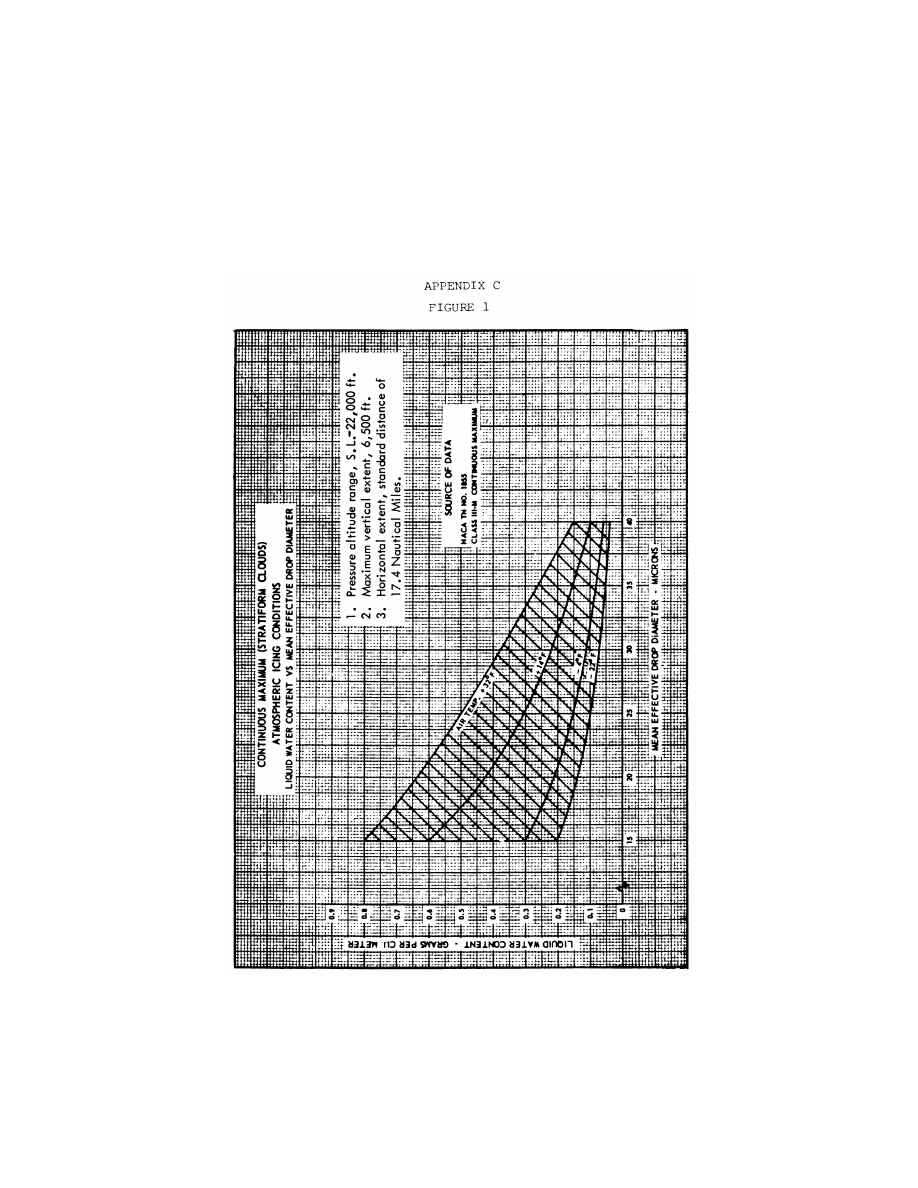
683
Federal Aviation Administration, DOT
Pt. 29, App. C
VerDate Sep<11>2014
09:06 Jun 28, 2024
Jkt 262046
PO 00000
Frm 00693
Fmt 8010
Sfmt 8006
Y:\SGML\262046.XXX
262046
EC28SE91.091</GPH>
jspears on DSK121TN23PROD with CFR
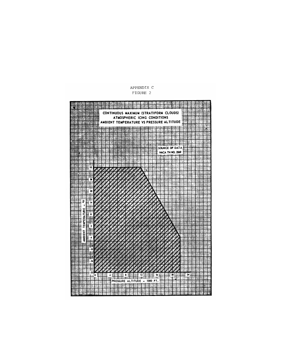
684
14 CFR Ch. I (1–1–24 Edition)
Pt. 29, App. C
VerDate Sep<11>2014
09:06 Jun 28, 2024
Jkt 262046
PO 00000
Frm 00694
Fmt 8010
Sfmt 8006
Y:\SGML\262046.XXX
262046
EC28SE91.092</GPH>
jspears on DSK121TN23PROD with CFR
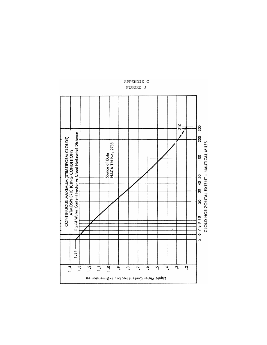
685
Federal Aviation Administration, DOT
Pt. 29, App. C
VerDate Sep<11>2014
09:06 Jun 28, 2024
Jkt 262046
PO 00000
Frm 00695
Fmt 8010
Sfmt 8006
Y:\SGML\262046.XXX
262046
EC28SE91.093</GPH>
jspears on DSK121TN23PROD with CFR
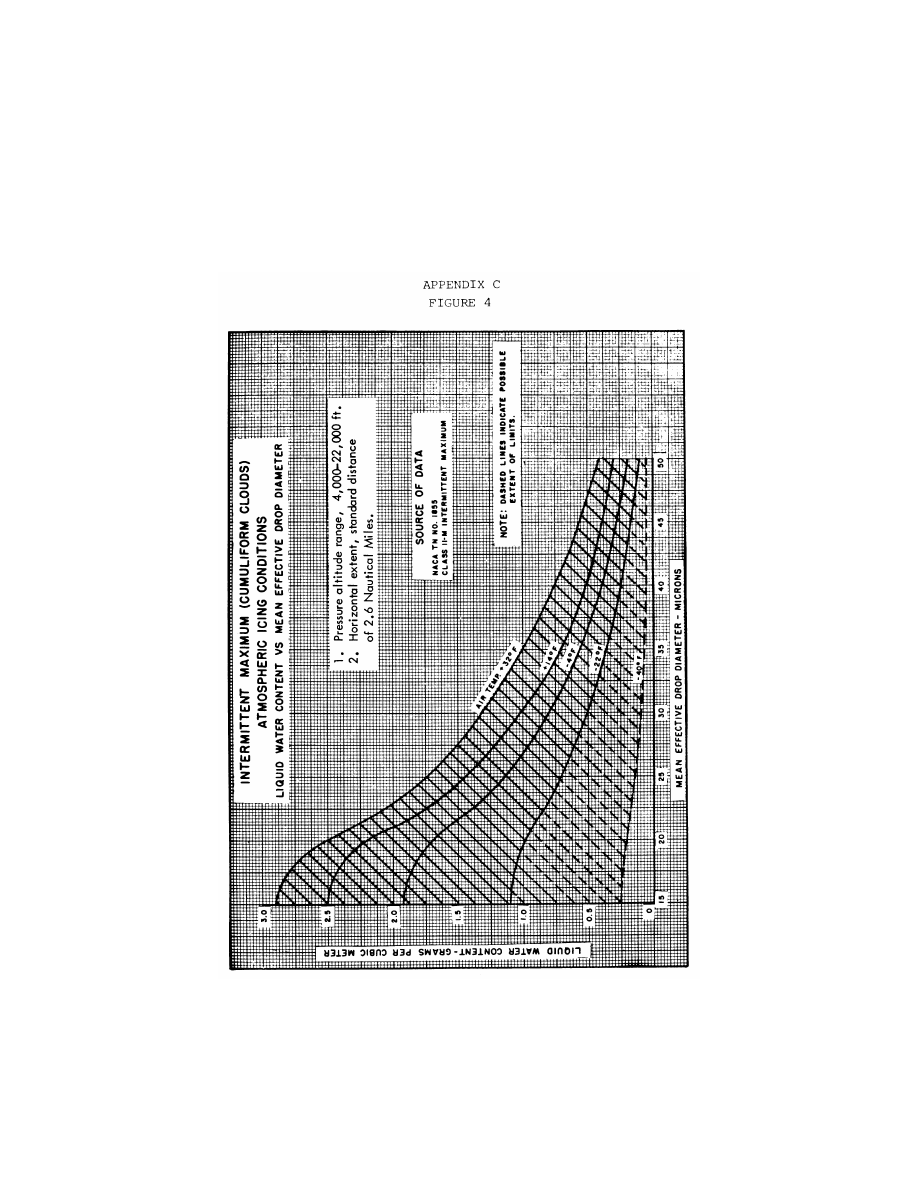
686
14 CFR Ch. I (1–1–24 Edition)
Pt. 29, App. C
VerDate Sep<11>2014
09:06 Jun 28, 2024
Jkt 262046
PO 00000
Frm 00696
Fmt 8010
Sfmt 8006
Y:\SGML\262046.XXX
262046
EC28SE91.094</GPH>
jspears on DSK121TN23PROD with CFR

687
Federal Aviation Administration, DOT
Pt. 29, App. C
VerDate Sep<11>2014
09:06 Jun 28, 2024
Jkt 262046
PO 00000
Frm 00697
Fmt 8010
Sfmt 8006
Y:\SGML\262046.XXX
262046
EC28SE91.095</GPH>
jspears on DSK121TN23PROD with CFR
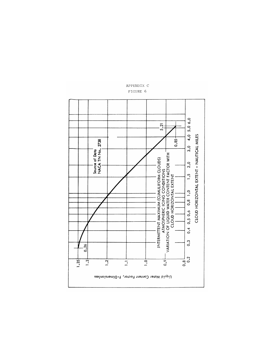
688
14 CFR Ch. I (1–1–24 Edition)
Pt. 29, App. C
[Amdt. 29–21, 48 FR 4393, Jan. 31, 1983]
VerDate Sep<11>2014
09:06 Jun 28, 2024
Jkt 262046
PO 00000
Frm 00698
Fmt 8010
Sfmt 8026
Y:\SGML\262046.XXX
262046
EC28SE91.096</GPH>
jspears on DSK121TN23PROD with CFR

689
Federal Aviation Administration, DOT
Pt. 29, App. D
A
PPENDIX
D
TO
P
ART
29—C
RITERIA FOR
D
EMONSTRATION
OF
E
MERGENCY
E
VACUATION
P
ROCEDURES
U
NDER
§ 29.803
(a) The demonstration must be conducted
either during the dark of the night or during
daylight with the dark of night simulated. If
the demonstration is conducted indoors dur-
ing daylight hours, it must be conducted in-
side a darkened hangar having doors and
windows covered. In addition, the doors and
windows of the rotorcraft must be covered if
the hangar illumination exceeds that of a
moonless night. Illumination on the floor or
ground may be used, but it must be kept low
and shielded against shining into the
rotorcraft’s windows or doors.
(b) The rotorcraft must be in a normal at-
titude with landing gear extended.
(c) Safety equipment such as mats or in-
verted liferafts may be placed on the floor or
ground to protect participants. No other
equipment that is not part of the rotorcraft’s
emergency evacuation equipment may be
used to aid the participants in reaching the
ground.
(d) Except as provided in paragraph (a) of
this appendix, only the rotorcraft’s emer-
gency lighting system may provide illumina-
tion.
(e) All emergency equipment required for
the planned operation of the rotorcraft must
be installed.
(f) Each external door and exit and each in-
ternal door or curtain must be in the takeoff
configuration.
(g) Each crewmember must be seated in
the normally assigned seat for takeoff and
must remain in that seat until receiving the
signal for commencement of the demonstra-
tion. For compliance with this section, each
crewmember must be—
(1) A member of a regularly scheduled line
crew; or
(2) A person having knowledge of the oper-
ation of exits and emergency equipment.
(h) A representative passenger load of per-
sons in normal health must be used as fol-
lows:
(1) At least 25 percent must be over 50
years of age, with at least 40 percent of these
being females.
(2) The remaining, 75 percent or less, must
be 50 years of age or younger, with at least
30 percent of these being females.
(3) Three life-size dolls, not included as
part of the total passenger load, must be car-
ried by passengers to simulate live infants 2
years old or younger, except for a total pas-
senger load of fewer than 44 but more than
19, one doll must be carried. A doll is not re-
quired for a 19 or fewer passenger load.
(4) Crewmembers, mechanics, and training
personnel who maintain or operate the rotor-
craft in the normal course of their duties
may not be used as passengers.
(i) No passenger may be assigned a specific
seat except as the Administrator may re-
quire. Except as required by paragraph (1) of
this appendix, no employee of the applicant
may be seated next to an emergency exit, ex-
cept as allowed by the Administrator.
(j) Seat belts and shoulder harnesses (as re-
quired) must be fastened.
(k) Before the start of the demonstration,
approximately one-half of the total average
amount of carry-on baggage, blankets, pil-
lows, and other similar articles must be dis-
tributed at several locations in the aisles
and emergency exit access ways to create
minor obstructions.
(l) No prior indication may be given to any
crewmember or passenger of the particular
exits to be used in the demonstration.
(m) The applicant may not practice, re-
hearse, or describe the demonstration for the
participants nor may any participant have
taken part in this type of demonstration
within the preceding 6 months.
(n) A pretakeoff passenger briefing may be
given. The passengers may also be advised to
follow directions of crewmembers, but not be
instructed on the procedures to be followed
in the demonstration.
(o) If safety equipment, as allowed by para-
graph (c) of this appendix, is provided, either
all passenger and cockpit windows must be
blacked out or all emergency exits must
have safety equipment to prevent disclosure
of the available emergency exits.
(p) Not more than 50 percent of the emer-
gency exits in the sides of the fuselage of a
rotorcraft that meet all of the requirements
applicable to the required emergency exits
for that rotorcraft may be used for dem-
onstration. Exits that are not to be used for
the demonstration must have the exit handle
deactivated or must be indicated by red
lights, red tape, or other acceptable means
placed outside the exits to indicate fire or
other reasons why they are unusable. The
exits to be used must be representative of all
the emergency exits on the rotorcraft and
must be designated by the applicant, subject
to approval by the Administrator. If in-
stalled, at least one floor level exit (Type I;
§ 29.807(a)(1)) must be used as required by
§ 29.807(c).
(q) All evacuees must leave the rotorcraft
by a means provided as part of the
rotorcraft’s equipment.
(r) Approved procedures must be fully uti-
lized during the demonstration.
(s) The evacuation time period is com-
pleted when the last occupant has evacuated
the rotorcraft and is on the ground.
[Amdt. 27–26, 55 FR 8005, Mar. 6, 1990]
VerDate Sep<11>2014
09:06 Jun 28, 2024
Jkt 262046
PO 00000
Frm 00699
Fmt 8010
Sfmt 8002
Y:\SGML\262046.XXX
262046
jspears on DSK121TN23PROD with CFR
690
14 CFR Ch. I (1–1–24 Edition)
Pt. 29, App. E
A
PPENDIX
E
TO
P
ART
29—HIRF E
NVI
-
RONMENTS
AND
E
QUIPMENT
HIRF
T
EST
L
EVELS
This appendix specifies the HIRF environ-
ments and equipment HIRF test levels for
electrical and electronic systems under
§ 29.1317. The field strength values for the
HIRF environments and laboratory equip-
ment HIRF test levels are expressed in root-
mean-square units measured during the peak
of the modulation cycle.
(a) HIRF environment I is specified in the
following table:
T
ABLE
I.—HIRF E
NVIRONMENT
I
Frequency
Field strength
(volts/meter)
Peak Average
10 kHz–2 MHz ...................................
50
50
2 MHz–30 MHz .................................
100
100
30 MHz–100 MHz .............................
50
50
100 MHz–400 MHz ...........................
100
100
400 MHz–700 MHz ...........................
700
50
700 MHz–1 GHz ................................
700
100
1 GHz–2 GHz ....................................
2,000
200
2 GHz–6 GHz ....................................
3,000
200
6 GHz–8 GHz ....................................
1,000
200
8 GHz–12 GHz ..................................
3,000
300
12 GHz–18 GHz ................................
2,000
200
18 GHz–40 GHz ................................
600
200
In this table, the higher field strength applies at the fre-
quency band edges.
(b) HIRF environment II is specified in the
following table:
T
ABLE
II.—HIRF E
NVIRONMENT
II
Frequency
Field strength
(volts/meter)
Peak Average
10 kHz–500 kHz ................................
20
20
500 kHz–2 MHz .................................
30
30
2 MHz–30 MHz .................................
100
100
30 MHz–100 MHz .............................
10
10
100 MHz–200 MHz ...........................
30
10
200 MHz–400 MHz ...........................
10
10
400 MHz–1 GHz ................................
700
40
1 GHz–2 GHz ....................................
1,300
160
2 GHz–4 GHz ....................................
3,000
120
4 GHz–6 GHz ....................................
3,000
160
6 GHz–8 GHz ....................................
400
170
8 GHz–12 GHz ..................................
1,230
230
12 GHz–18 GHz ................................
730
190
18 GHz–40 GHz ................................
600
150
In this table, the higher field strength applies at the fre-
quency band edges.
(c) HIRF environment III is specified in the
following table:
T
ABLE
III.—HIRF E
NVIRONMENT
III
Frequency
Field strength
(volts/meter)
Peak Average
10 kHz–100 kHz ................................
150
150
100 kHz–400 MHz .............................
200
200
400 MHz–700 MHz ...........................
730
200
700 MHz–1 GHz ................................
1,400
240
1 GHz–2 GHz ....................................
5,000
250
2 GHz–4 GHz ....................................
6,000
490
4 GHz–6 GHz ....................................
7,200
400
6 GHz–8 GHz ....................................
1,100
170
8 GHz–12 GHz ..................................
5,000
330
12 GHz–18 GHz ................................
2,000
330
18 GHz–40 GHz ................................
1,000
420
In this table, the higher field strength applies at the fre-
quency band edges.
(d)
Equipment HIRF Test Level 1. (1) From 10
kilohertz (kHz) to 400 megahertz (MHz), use
conducted susceptibility tests with contin-
uous wave (CW) and 1 kHz square wave mod-
ulation with 90 percent depth or greater. The
conducted susceptibility current must start
at a minimum of 0.6 milliamperes (mA) at 10
kHz, increasing 20 decibel (dB) per frequency
decade to a minimum of 30 mA at 500 kHz.
(2) From 500 kHz to 40 MHz, the conducted
susceptibility current must be at least 30
mA.
(3) From 40 MHz to 400 MHz, use conducted
susceptibility tests, starting at a minimum
of 30 mA at 40 MHz, decreasing 20 dB per fre-
quency decade to a minimum of 3 mA at 400
MHz.
(4) From 100 MHz to 400 MHz, use radiated
susceptibility tests at a minimum of 20 volts
per meter (V/m) peak with CW and 1 kHz
square wave modulation with 90 percent
depth or greater.
(5) From 400 MHz to 8 gigahertz (GHz), use
radiated susceptibility tests at a minimum
of 150 V/m peak with pulse modulation of 4
percent duty cycle with a 1 kHz pulse repeti-
tion frequency. This signal must be switched
on and off at a rate of 1 Hz with a duty cycle
of 50 percent.
(e)
Equipment HIRF Test Level 2. Equipment
HIRF test level 2 is HIRF environment II in
table II of this appendix reduced by accept-
able aircraft transfer function and attenu-
ation curves. Testing must cover the fre-
quency band of 10 kHz to 8 GHz.
(f)
Equipment HIRF Test Level 3. (1) From 10
kHz to 400 MHz, use conducted susceptibility
tests, starting at a minimum of 0.15 mA at 10
kHz, increasing 20 dB per frequency decade
to a minimum of 7.5 mA at 500 kHz.
(2) From 500 kHz to 40 MHz, use conducted
susceptibility tests at a minimum of 7.5 mA.
(3) From 40 MHz to 400 MHz, use conducted
susceptibility tests, starting at a minimum
of 7.5 mA at 40 MHz, decreasing 20 dB per fre-
quency decade to a minimum of 0.75 mA at
400 MHz.
VerDate Sep<11>2014
09:06 Jun 28, 2024
Jkt 262046
PO 00000
Frm 00700
Fmt 8010
Sfmt 8002
Y:\SGML\262046.XXX
262046
jspears on DSK121TN23PROD with CFR

691
Federal Aviation Administration, DOT
§ 31.12
(4) From 100 MHz to 8 GHz, use radiated
susceptibility tests at a minimum of 5 V/m.
[Doc. No. FAA–2006–23657, 72 FR 44028, Aug. 6,
2007]
PART 31—AIRWORTHINESS STAND-
ARDS: MANNED FREE BAL-
LOONS
Subpart A—General
Sec.
31.1
Applicability.
Subpart B—Flight Requirements
31.12
Proof of compliance.
31.14
Weight limits.
31.16
Empty weight.
31.17
Performance: Climb.
31.19
Performance: Uncontrolled descent.
31.20
Controllability.
Subpart C—Strength Requirements
31.21
Loads.
31.23
Flight load factor.
31.25
Factor of safety.
31.27
Strength.
Subpart D—Design Construction
31.31
General.
31.33
Materials.
31.35
Fabrication methods.
31.37
Fastenings.
31.39
Protection.
31.41
Inspection provisions.
31.43
Fitting factor.
31.45
Fuel cells.
31.46
Pressurized fuel systems.
31.47
Burners.
31.49
Control systems.
31.51
Ballast.
31.53
Drag rope.
31.55
Deflation means.
31.57
Rip cords.
31.59
Trapeze, basket, or other means pro-
vided for occupants.
31.61
Static discharge.
31.63
Safety belts.
31.65
Position lights.
Subpart E—Equipment
31.71
Function and installation.
Subpart F—Operating Limitations and
Information
31.81
General.
31.82
Instructions for Continued Airworthi-
ness.
31.83
Conspicuity.
31.85
Required basic equipment.
A
PPENDIX
A
TO
P
ART
31—I
NSTRUCTIONS FOR
C
ONTINUED
A
IRWORTHINESS
A
UTHORITY
: 49 U.S.C. 106(g), 40113, 44701–
44702, 44704.
S
OURCE
: Docket No. 1437, 29 FR 8258, July 1,
1964, as amended by Amdt. 31–1, 29 FR 14563,
Oct. 24, 1964, unless otherwise noted.
Subpart A—General
§ 31.1
Applicability.
(a) This part prescribes airworthiness
standards for the issue of type certifi-
cates and changes to those certificates,
for manned free balloons.
(b) Each person who applies under
Part 21 for such a certificate or change
must show compliance with the appli-
cable requirements of this part.
(c) For purposes of this part—
(1) A captive gas balloon is a balloon
that derives its lift from a captive
lighter-than-air gas;
(2) A hot air balloon is a balloon that
derives its lift from heated air;
(3) The envelope is the enclosure in
which the lifting means is contained;
(4) The basket is the container, sus-
pended beneath the envelope, for the
balloon occupants;
(5) The trapeze is a harness or is a
seat consisting of a horizontal bar or
platform suspended beneath the enve-
lope for the balloon occupants; and
(6) The design maximum weight is
the maximum total weight of the bal-
loon, less the lifting gas or air.
[Doc. No. 1437, 29 FR 8258, July 1, 1964, as
amended by Amdt. 31–3, 41 FR 55474, Dec. 20,
1976]
Subpart B—Flight Requirements
§ 31.12
Proof of compliance.
(a) Each requirement of this subpart
must be met at each weight within the
range of loading conditions for which
certification is requested. This must be
shown by—
(1) Tests upon a balloon of the type
for which certification is requested or
by calculations based on, and equal in
accuracy to, the results of testing; and
(2) Systematic investigation of each
weight if compliance cannot be reason-
ably inferred from the weights inves-
tigated.
VerDate Sep<11>2014
09:06 Jun 28, 2024
Jkt 262046
PO 00000
Frm 00701
Fmt 8010
Sfmt 8010
Y:\SGML\262046.XXX
262046
jspears on DSK121TN23PROD with CFR