
765
Federal Aviation Administration, DOT
Pt. 36
cross-references to the Airworthiness Limi-
tations section of the manual must also be
included. In addition, the applicant must in-
clude an inspection program that includes
the frequency and extent of the inspections
necessary to provide for the continued air-
worthiness of the propeller.
(7) Troubleshooting information describing
probable malfunctions, how to recognize
those malfunctions, and the remedial action
for those malfunctions.
(8) Information describing the order and
method of removing and replacing propeller
parts with any necessary precautions to be
taken.
(9) A list of the special tools needed for
maintenance other than for overhauls.
(b)
Propeller Overhaul Section. (1) Dis-
assembly information including the order
and method of disassembly for overhaul.
(2) Cleaning and inspection instructions
that cover the materials and apparatus to be
used and methods and precautions to be
taken during overhaul. Methods of overhaul
inspection must also be included.
(3) Details of all fits and clearances rel-
evant to overhaul.
(4) Details of repair methods for worn or
otherwise substandard parts and components
along with information necessary to deter-
mine when replacement is necessary.
(5) The order and method of assembly at
overhaul.
(6) Instructions for testing after overhaul.
(7) Instructions for storage preparation in-
cluding any storage limits.
(8) A list of tools needed for overhaul.
A
35.4
AIRWORTHINESS LIMITATIONS SECTION
The Instructions for Continued Airworthi-
ness must contain a section titled Airworthi-
ness Limitations that is segregated and
clearly distinguishable from the rest of the
document. This section must set forth each
mandatory replacement time, inspection in-
terval, and related procedure required for
type certification. This section must contain
a legible statement in a prominent location
that reads: ‘‘The Airworthiness Limitations
section is FAA approved and specifies main-
tenance required under §§ 43.16 and 91.403 of
the Federal Aviation Regulations unless an
alternative program has been FAA ap-
proved.’’
[Amdt. 35–5, 45 FR 60182, Sept. 11, 1980, as
amended by Amdt. 35–6, 54 FR 34330, Aug. 18,
1989]
PART 36—NOISE STANDARDS: AIR-
CRAFT TYPE AND AIRWORTHI-
NESS CERTIFICATION
Subpart A—General
Sec.
36.1
Applicability and definitions.
36.2
Requirements as of date of application.
36.3
Compatibility with airworthiness re-
quirements.
36.5
Limitation of part.
36.6
Incorporations by reference.
36.7
Acoustical change: Transport category
large airplanes and jet airplanes.
36.9
Acoustical change: Propeller-driven
small airplanes and propeller-driven
commuter category airplanes.
36.11
Acoustical change: Helicopters.
36.13
Acoustical change: Tiltrotor aircraft.
Subpart B—Transport Category Large
Airplanes and Jet Airplanes
36.101
Noise measurement and evaluation.
36.103
Noise limits.
36.105
Flight Manual Statement of Chapter
4 equivalency.
36.106
Flight Manual statement of Chapter
14 noise level equivalency.
Subpart C
[
Reserved
]
Subpart D—Noise Limits for Supersonic
Transport Category Airplanes
36.301
Noise limits: Concorde.
Subpart E
[
Reserved
]
Subpart F—Propeller Driven Small Airplanes
and Propeller-Driven, Commuter Cat-
egory Airplanes
36.501
Noise limits.
Subpart G
[
Reserved
]
Subpart H—Helicopters
36.801
Noise measurement.
36.803
Noise evaluation and calculation.
36.805
Noise limits.
Subparts I–J
[
Reserved
]
Subpart K—Tiltrotors
36.1101
Noise measurement and evaluation.
36.1103
Noise limits.
Subparts L–N
[
Reserved
]
VerDate Sep<11>2014
09:06 Jun 28, 2024
Jkt 262046
PO 00000
Frm 00775
Fmt 8010
Sfmt 8006
Y:\SGML\262046.XXX
262046
jspears on DSK121TN23PROD with CFR

766
14 CFR Ch. I (1–1–24 Edition)
§ 36.1
Subpart O—Documentation, Operating
Limitations and Information
36.1501
Procedures, noise levels and other
information.
36.1581
Manuals, markings, and placards.
36.1583
Noncomplying agricultural and fire
fighting airplanes.
A
PPENDIX
A
TO
P
ART
36—A
IRCRAFT
N
OISE
M
EASUREMENT
AND
E
VALUATION
U
NDER
§ 36.101
A
PPENDIX
B
TO
P
ART
36—N
OISE
L
EVELS FOR
T
RANSPORT
C
ATEGORY
AND
J
ET
A
IR
-
PLANES
U
NDER
§ 36.103
A
PPENDIXES
C–E
TO
P
ART
36 [R
ESERVED
]
A
PPENDIX
F
TO
P
ART
36—F
LYOVER
N
OISE
R
E
-
QUIREMENTS
FOR
P
ROPELLER
-D
RIVEN
S
MALL
A
IRPLANE AND
P
ROPELLER
-D
RIVEN
,
C
OMMUTER
C
ATEGORY
A
IRPLANE
C
ERTIFI
-
CATION
T
ESTS
P
RIOR TO
D
ECEMBER
22, 1988
A
PPENDIX
G
TO
P
ART
36—T
AKEOFF
N
OISE
R
E
-
QUIREMENTS
FOR
P
ROPELLER
-D
RIVEN
S
MALL
A
IRPLANE AND
P
ROPELLER
-D
RIVEN
,
C
OMMUTER
C
ATEGORY
A
IRPLANE
C
ERTIFI
-
CATION
T
ESTS ON OR
A
FTER
D
ECEMBER
22,
1988
A
PPENDIX
H
TO
P
ART
36—N
OISE
R
EQUIRE
-
MENTS FOR
H
ELICOPTERS
U
NDER
S
UBPART
H
A
PPENDIX
I
TO
P
ART
36 [R
ESERVED
]
A
PPENDIX
J
TO
P
ART
36—A
LTERNATIVE
N
OISE
C
ERTIFICATION
P
ROCEDURE
F
OR
H
ELI
-
COPTERS
U
NDER
S
UBPART
H H
AVING
A
M
AXIMUM
C
ERTIFICATED
T
AKEOFF
W
EIGHT
O
F
N
OT
M
ORE
T
HAN
7,000 P
OUNDS
A
PPENDIX
K
TO
P
ART
36—N
OISE
R
EQUIRE
-
MENTS FOR
T
ILTROTORS
U
NDER
S
UBPART
K
A
UTHORITY
: 42 U.S.C. 4321
et seq.; 49 U.S.C.
106(g), 40113, 44701–44702, 44704, 44715; sec. 305,
Pub. L. 96–193, 94 Stat. 50, 57; E.O. 11514, 35
FR 4247, 3 CFR, 1966–1970 Comp., p. 902.
S
OURCE
: Docket No. 9337, 34 FR 18364, Nov.
18, 1969, unless otherwise noted.
Subpart A—General
§ 36.1
Applicability and definitions.
(a) This part prescribes noise stand-
ards for the issue of the following cer-
tificates:
(1) Type certificates, and changes to
those certificates, and standard air-
worthiness certificates, for subsonic
transport category large airplanes, and
for subsonic jet airplanes regardless of
category.
(2) Type certificates and changes to
those certificates, standard airworthi-
ness certificates, and restricted cat-
egory airworthiness certificates, for
propeller-driven, small airplanes, and
for propeller-driven, commuter cat-
egory airplanes except those airplanes
that are designed for ‘‘agricultural air-
craft operations’’ (as defined in § 137.3
of this chapter, as effective on January
1, 1966) or for dispersing fire fighting
materials to which § 36.1583 of this part
does not apply.
(3) A type certificate and changes to
that certificate, and standard air-
worthiness certificates, for Concorde
airplanes.
(4) Type certificates, and changes to
those certificates, for helicopters ex-
cept those helicopters that are des-
ignated exclusively for ‘‘agricultural
aircraft operations’’ (as defined in
§ 137.3 of this chapter, as effective on
January 1, 1966), for dispensing fire
fighting materials, or for carrying ex-
ternal loads (as defined in § 133.1(b) of
this chapter, as effective on December
20, 1976).
(5) Type certificates, changes to
those certificates, and standard air-
worthiness certificates, for tiltrotors.
(b) Each person who applies under
Part 21 of this chapter for a type of air-
worthiness certificate specified in this
part must show compliance with the
applicable requirements of this part, in
addition to the applicable airworthi-
ness requirements of this chapter.
(c) Each person who applies under
Part 21 of this chapter for approval of
an acoustical change described in
§ 21.93(b) of this chapter must show that
the aircraft complies with the applica-
ble provisions of §§ 36.7, 36.9, 36.11 or
36.13 of this part in addition to the ap-
plicable airworthiness requirements of
this chapter.
(d) Each person who applies for the
original issue of a standard airworthi-
ness certificate for a transport cat-
egory large airplane or for a jet air-
plane under § 21.183 must, regardless of
date of application, show compliance
with the following provisions of this
part (including appendix B):
(1) The provisions of this part in ef-
fect on December 1, 1969, for subsonic
airplanes that have not had any flight
time before—
(i) December 1, 1973, for airplanes
with maximum weights greater than
75,000 pounds, except for airplanes that
are powered by Pratt & Whitney Turbo
Wasp JT3D series engines;
(ii) December 31, 1974, for airplanes
with maximum weights greater than
VerDate Sep<11>2014
09:06 Jun 28, 2024
Jkt 262046
PO 00000
Frm 00776
Fmt 8010
Sfmt 8010
Y:\SGML\262046.XXX
262046
jspears on DSK121TN23PROD with CFR

767
Federal Aviation Administration, DOT
§ 36.1
75,000 pounds and that are powered by
Pratt & Whitney Turbo Wasp JT3D se-
ries engines; and
(iii) December 31, 1974, for airplanes
with maximum weights of 75,000 pounds
and less.
(2) The provisions of this part in ef-
fect on October 13, 1977, including the
stage 2 noise limits, for Concorde air-
planes that have not had flight time
before January 1, 1980.
(e) Each person who applies for the
original issue of a standard airworthi-
ness certificate under § 21.183, or for the
original issue of a restricted category
airworthiness certificate under § 21.185,
for propeller-driven, commuter cat-
egory airplanes for a propeller driven
small airplane that has not had any
flight time before January 1, 1980, must
show compliance with the applicable
provisions of this part.
(f) For the purpose of showing com-
pliance with this part for transport
category large airplanes and jet air-
planes regardless of category, the fol-
lowing terms have the following mean-
ings:
(1) A ‘‘Stage 1 noise level’’ means a
flyover, lateral or approach noise level
greater than the Stage 2 noise limits
prescribed in section B36.5(b) of appen-
dix B of this part.
(2) A ‘‘Stage 1 airplane’’ means an
airplane that has not been shown under
this part to comply with the flyover,
lateral, and approach noise levels re-
quired for Stage 2 or Stage 3 airplanes.
(3) A ‘‘Stage 2 noise level’’ means a
noise level at or below the Stage 2
noise limits prescribed in section
B36.5(b) of appendix B of this part but
higher than the Stage 3 noise limits
prescribed in section B36.5(c) of appen-
dix B of this part.
(4) A ‘‘Stage 2 airplane’’ means an
airplane that has been shown under
this part to comply with Stage 2 noise
levels prescribed in section B36.5(b) of
appendix B of this part (including use
of the applicable tradeoff provisions
specified in section B36.6) and that does
not comply with the requirements for a
Stage 3 airplane.
(5) A ‘‘Stage 3 noise level’’ means a
noise level at or below the Stage 3
noise limits prescribed in section
B36.5(c) of appendix B of this part.
(6) A ‘‘Stage 3 airplane’’ means an
airplane that has been shown under
this part to comply with Stage 3 noise
levels prescribed in section B36.5(c) of
appendix B of this part (including use
of the applicable tradeoff provisions
specified in section B36.6).
(7) A ‘‘subsonic airplane’’ means an
airplane for which the maximum oper-
ating limit speed, M
mo
, does not exceed
a Mach number of 1.
(8) A ‘‘supersonic airplane’’ means an
airplane for which the maximum oper-
ating limit speed, M
mo
, exceeds a Mach
number of 1.
(9) A ‘‘Stage 4 noise level’’ means a
noise level at or below the Stage 4
noise limit prescribed in section
B36.5(d) of appendix B of this part.
(10) A ‘‘Stage 4 airplane’’ means an
airplane that has been shown under
this part not to exceed the Stage 4
noise limit prescribed in section
B36.5(d) of appendix B of this part.
(11) A ‘‘Chapter 4 noise level’’ means
a noise level at or below the maximum
noise level prescribed in Chapter 4,
Paragraph 4.4, Maximum Noise Levels,
of the International Civil Aviation Or-
ganization (ICAO) Annex 16, Volume I,
Amendment 7, effective March 21, 2002.
[Incorporated by reference, see § 36.6].
(12) A ‘‘Stage 5 noise level’’ means a
noise level at or below the Stage 5
noise limit prescribed in section
B36.5(e) of appendix B to this part.
(13) A ‘‘Stage 5 airplane’’ means an
airplane that has been shown under
this part not to exceed the Stage 5
noise limit prescribed in section
B36.5(e) of appendix B to this part.
(14) A ‘‘Chapter 14 noise level’’ means
a noise level at or below the Chapter 14
maximum noise level prescribed in
Chapter 14 of the ICAO Annex 16, Vol-
ume 1, Seventh Edition, Amendment
11–B (Incorporated by reference, see
§ 36.6).
(g) For the purpose of showing com-
pliance with this part for transport
category large airplanes and jet air-
planes regardless of category, each air-
plane may not be identified as com-
plying with more than one stage or
configuration simultaneously.
(h) For the purpose of showing com-
pliance with this part, for helicopters
in the primary, normal, transport, and
VerDate Sep<11>2014
09:06 Jun 28, 2024
Jkt 262046
PO 00000
Frm 00777
Fmt 8010
Sfmt 8010
Y:\SGML\262046.XXX
262046
jspears on DSK121TN23PROD with CFR

768
14 CFR Ch. I (1–1–24 Edition)
§ 36.1
restricted categories, the following
terms have the specified meanings:
(1)
Stage 1 noise level means a takeoff,
flyover, or approach noise level greater
than the Stage 2 noise limits pre-
scribed in section H36.305 of appendix H
of this part, or a flyover noise level
greater than the Stage 2 noise limits
prescribed in section J36.305 of appen-
dix J of this part.
(2)
Stage 1 helicopter means a heli-
copter that has not been shown under
this part to comply with the takeoff,
flyover, and approach noise levels re-
quired for Stage 2 helicopters as pre-
scribed in section H36.305 of appendix H
of this part, or a helicopter that has
not been shown under this part to com-
ply with the flyover noise level re-
quired for Stage 2 helicopters as pre-
scribed in section J36.305 of appendix J
of this part.
(3)
Stage 2 noise level means a takeoff,
flyover, or approach noise level at or
below the Stage 2 noise limits pre-
scribed in section H36.305 of appendix H
of this part, or a flyover noise level at
or below the Stage 2 limit prescribed in
section J36.305 of appendix J of this
part.
(4)
Stage 2 helicopter means a heli-
copter that has been shown under this
part to comply with Stage 2 noise lim-
its (including applicable tradeoffs) pre-
scribed in section H36.305 of appendix H
of this part, or a helicopter that has
been shown under this part to comply
with the Stage 2 noise limit prescribed
in section J36.305 of appendix J of this
part.
(5) A ‘‘Stage 3 noise level’’ means a
takeoff, flyover, or approach noise
level at or below the Stage 3 noise lim-
its prescribed in section H36.305 of ap-
pendix H of this part, or a flyover noise
level at or below the Stage 3 noise
limit prescribed in section J36.305 of
appendix J of this part.
(6) A ‘‘Stage 3 helicopter’’ means a
helicopter that has been shown under
this part to comply with the Stage 3
noise limits (including applicable
tradeoffs) prescribed in section H36.305
of appendix H of this part, or a heli-
copter that has been shown under this
part to comply with the Stage 3 noise
limit prescribed in section J36.305 of
appendix J of this part.
(7)
Maximum normal operating RPM
means the highest rotor speed cor-
responding to the airworthiness limit
imposed by the manufacturer and ap-
proved by the FAA. Where a tolerance
on the highest rotor speed is specified,
the maximum normal operating rotor
speed is the highest rotor speed for
which that tolerance is given. If the
rotor speed is automatically linked
with flight condition, the maximum
normal operating rotor speed cor-
responding with the reference flight
condition must be used during the
noise certification procedure. If rotor
speed can be changed by pilot action,
the highest normal operating rotor
speed specified in the flight manual
limitation section for reference condi-
tions must be used during the noise
certification procedure.
(i) For the purpose of showing com-
pliance with this part for tiltrotors,
the following terms have the specified
meanings:
Airplane mode means a configuration
with nacelles on the down stops (axis
aligned horizontally) and rotor speed
set to cruise revolutions per minute
(RPM).
Airplane mode RPM means the lower
range of rotor rotational speed in RPM
defined for the airplane mode cruise
flight condition.
Fixed operation points mean des-
ignated nacelle angle positions selected
for airworthiness reference. These are
default positions used to refer to nor-
mal nacelle positioning operation of
the aircraft. The nacelle angle is con-
trolled by a self-centering switch.
When the nacelle angle is 0 degrees
(airplane mode) and the pilot moves
the nacelle switch upwards, the na-
celles are programmed to automati-
cally turn to the first default position
(for example, 60 degrees) where they
will stop. A second upward move of the
switch will tilt the nacelle to the sec-
ond default position (for example, 75
degrees). Above the last default posi-
tion, the nacelle angle can be set to
any angle up to approximately 95 de-
grees by moving the switch in the up or
down direction. The number and posi-
tion of the fixed operation points may
vary on different tiltrotor configura-
tions.
VerDate Sep<11>2014
09:06 Jun 28, 2024
Jkt 262046
PO 00000
Frm 00778
Fmt 8010
Sfmt 8010
Y:\SGML\262046.XXX
262046
jspears on DSK121TN23PROD with CFR

769
Federal Aviation Administration, DOT
§ 36.5
Nacelle angle is defined as the angle
between the rotor shaft centerline and
the longitudinal axis of the aircraft fu-
selage.
Tiltrotor means a class of aircraft ca-
pable of vertical take-off and landing,
within the powered-lift category, with
rotors mounted at or near the wing tips
that vary in pitch from near vertical to
near horizontal configuration relative
to the wing and fuselage.
Vertical takeoff and landing (VTOL)
mode means the aircraft state or con-
figuration having the rotors orientated
with the axis of rotation in a vertical
manner (
i.e., nacelle angle of approxi-
mately 90 degrees) for vertical takeoff
and landing operations.
V
CON
is defined as the maximum au-
thorized speed for any nacelle angle in
VTOL/Conversion mode.
VTOL/Conversion mode is all approved
nacelle positions where the design op-
erating rotor speed is used for hover
operations.
VTOL mode RPM means highest range
of RPM that occur for takeoff, ap-
proach, hover, and conversion condi-
tions.
[Doc. No. 13243, Amdt. 36–4, 40 FR 1034, Jan.
6, 1975]
E
DITORIAL
N
OTE
: For F
EDERAL
R
EGISTER
ci-
tations affecting § 36.1, see the List of CFR
Sections Affected, which appears in the
Finding Aids section of the printed volume
and at
www.govinfo.gov.
§ 36.2
Requirements as of date of ap-
plication.
(a) Section 21.17 of this chapter not-
withstanding, each person who applies
for a type certificate for an aircraft
covered by this part, must show that
the aircraft meets the applicable re-
quirements of this part that are effec-
tive on the date of application for that
type certificate. When the time inter-
val between the date of application for
the type certificate and the issuance of
the type certificate exceeds 5 years, the
applicant must show that the aircraft
meets the applicable requirements of
this part that were effective on a date,
to be selected by the applicant, not
earlier than 5 years before the issue of
the type certificate.
(b) Section 21.101(a) of this chapter
notwithstanding, each person who ap-
plies for an acoustical change to a type
design specified in § 21.93(b) of this
chapter must show compliance with
the applicable requirements of this
part that are effective on the date of
application for the change in type de-
sign. When the time interval between
the date of application for the change
in type design and the issuance of the
amended or supplemental type certifi-
cate exceeds 5 years, the applicant
must show that the aircraft meets the
applicable requirements of this part
that were effective on a date, to be se-
lected by the applicant, not earlier
than 5 years before the issue of the
amended or supplemental type certifi-
cate.
(c) If an applicant elects to comply
with a standard in this part that was
effective after the filing of the applica-
tion for a type certificate or change to
a type design, the election:
(1) Must be approved by the FAA;
(2) Must include standards adopted
between the date of application and the
date of the election;
(3) May include other standards
adopted after the standard elected by
the applicant as determined by the
FAA.
[Amdt. 36–54, 67 FR 45211, July 8, 2002; Amdt.
36–24, 67 FR 63195, Oct. 10, 2002]
§ 36.3
Compatibility with airworthi-
ness requirements.
It must be shown that the aircraft
meets the airworthiness regulations
constituting the type certification
basis of the aircraft under all condi-
tions in which compliance with this
part is shown, and that all procedures
used in complying with this part, and
all procedures and information for the
flight crew developed under this part,
are consistent with the airworthiness
regulations constituting the type cer-
tification basis of the aircraft.
[Doc. No. 9337, 34 FR 18364, Nov. 18, 1969, as
amended by Amdt. 36–14, 53 FR 3540, Feb. 5,
1988]
§ 36.5
Limitation of part.
Pursuant to 49 U.S.C. 44715, the noise
levels in this part have been deter-
mined to be as low as is economically
reasonable, technologically prac-
ticable, and appropriate to the type of
aircraft to which they apply. No deter-
mination is made, under this part, that
VerDate Sep<11>2014
09:06 Jun 28, 2024
Jkt 262046
PO 00000
Frm 00779
Fmt 8010
Sfmt 8010
Y:\SGML\262046.XXX
262046
jspears on DSK121TN23PROD with CFR

770
14 CFR Ch. I (1–1–24 Edition)
§ 36.6
these noise levels are or should be ac-
ceptable or unacceptable for operation
at, into, or out of, any airport.
[Doc. No. 9337, 34 FR 18364, Nov. 18, 1969, as
amended by Docket FAA–2015–3782, Amdt. 36–
31, 82 FR 46129, Oct. 4, 2017]
§ 36.6
Incorporation by reference.
(a) Certain material is incorporated
by reference into this part with the ap-
proval of the Director of the Federal
Register under 5 U.S.C. 552(a) and 1
CFR part 51. All approved material is
available for inspection at the loca-
tions in this paragraph (a) and may be
obtained from the sources detailed in
paragraphs (a)(1) through (12) of this
section.
(1) The U.S. Department of Transpor-
tation, Docket Operations, West Build-
ing Ground Floor, Room W12–140, 1200
New Jersey Avenue SE., Washington,
DC 20590.
(2) Federal Aviation Administration
New England Regional Headquarters,
12 New England Executive Park, Bur-
lington, MA 01801.
(3) Federal Aviation Administration
Eastern Region Headquarters, Federal
Building, John F. Kennedy Inter-
national Airport, Jamaica, NY 11430.
(4) Federal Aviation Administration
Southern Region Headquarters, 1701
Columbia Avenue, College Park, GA
30337.
(5) Federal Aviation Administration
Great Lakes Region Headquarters,
O’Hare Lake Office Center, 2300 East
Devon Avenue, Des Plaines, IL 60018.
(6) Federal Aviation Administration
Central Region Headquarters, Federal
Building, 601 East 12th Street, Kansas
City, MO 64106.
(7) Federal Aviation Administration
Southwest Region Headquarters, 2601
Meacham Boulevard, Fort Worth, TX
76137.
(8) Federal Aviation Administration
Northwest Mountain Region Head-
quarters, 1601 Lind Avenue SW,
Renton, WA 98055.
(9) Federal Aviation Administration
Western Pacific Region Headquarters,
15000 Aviation Boulevard, Hawthorne,
CA 92007.
(10) Federal Aviation Administration
Alaskan Region Headquarters, 222 West
7th Avenue, #14, Anchorage, AK 99513.
(11) Federal Aviation Administration
European Office Headquarters, 15 Rue
de la Loi, Third Floor, B–1040, Brussels,
Belgium.
(12) The National Archives and
Records Administration (NARA). For
information on the availability of this
information at NARA, call 202–741–6030
or go to
http://www.archives.gov/fed-
eral
_
register/code
_
of
_
federal
_
regulations/
ibr
_
locations.html.
(b) International Civil Aviation Orga-
nization (ICAO), Document Sales Unit,
999 University Street, Montreal, Que-
bec, H3C 5H7, Canada.
http://
www.icao.int/publications/Pages/de-
fault.aspx.
(1) International Standards and Rec-
ommended Practices, Annex 16 to the
Convention on International Civil
Aviation, Environmental Protection,
Volume I, Aircraft Noise, Third Edi-
tion, July 1993, Amendment 7 effective
March 21, 2002, IBR approved for
§ 36.1(f), and appendices A and B to part
36.
(2) International Standards and Rec-
ommended Practices, Annex 16 to the
Convention on International Civil
Aviation, Environmental Protection,
Volume I, Aircraft Noise, Seventh Edi-
tion, July 2014, Amendment 11–B, appli-
cable January 1, 2015, IBR approved for
§ 36.1(f) and appendices A and B to part
36.
(c) International Electrotechnical
Commission (IEC) 3 Rue de Varembe,
Case Postale 131, 1211 Geneva 20, Swit-
zerland,
http://www.iec.ch/standardsdev/
publications/?ref=menu.
(1) Publication No. 179, Precision
Level Sound Meters, (IEC 179) 1973, IBR
approved for appendix F to part 36.
(2) Publication No. 561, Electro-
acoustical Measuring Equipment for
Aircraft Noise Certification, first edi-
tion, 1976, (IEC 561), IBR approved for
appendices G and J to part 36.
(3) Publication No. 651, Sound Level
Meters, first edition, 1979, (IEC 651),
IBR approved for appendices G and J to
part 36.
(4) Publication No. 804, Integrating-
averaging Sound Level Meters, first
edition, 1985, (IEC 804), IBR approved
for appendix J to part 36.
(5) Publication No. 61094–3, Measure-
ment Microphones—Part 3: Primary
Method for Free-Field Calibration of
VerDate Sep<11>2014
09:06 Jun 28, 2024
Jkt 262046
PO 00000
Frm 00780
Fmt 8010
Sfmt 8010
Y:\SGML\262046.XXX
262046
jspears on DSK121TN23PROD with CFR

771
Federal Aviation Administration, DOT
§ 36.7
Laboratory Standard Microphones by
the Reciprocity Technique, edition 1.0,
1995 (IEC 61094–3) IBR approved for ap-
pendix A to part 36.
(6) Publication No. 61094–4, Measure-
ment Microphones—Part 4: Specifica-
tions for Working Standard Micro-
phones, edition 1.0, 1995, (IEC 61094–4)
IBR approved for appendix A to part 36.
(7) Publication No. 61260,
Electroacoustics-Octave-Band and
Fractional-Octave-Band Filters, edi-
tion 1.0, 1995, (IEC 61260), IBR approved
for appendix A to part 36.
(8) Publication No, 60942,
Electroacoustics-Sound Calibrators,
edition 2.0, 1997, (IEC 60942) IBR ap-
proved for appendix A to part 36.
(d) Society of Automotive Engineers,
Inc. (SAE), 400 Commonwealth Drive,
Warrentown, PA 15096,
http://
www.sae.org/pubs/.
(1) ARP 866A, Standard Values at At-
mospheric Absorption as a Function of
Temperature and Humidity for use in
Evaluating Aircraft Flyover Noise,
March 15, 1975, IBR approved for appen-
dix H to part 36.
(2) [Reserved]
[Doc. No. FAA–2015–3782, Amdt. No. 36–31, 82
FR 46129, Oct. 4, 2017]
§ 36.7
Acoustical change: Transport
category large airplanes and jet air-
planes.
(a)
Applicability. This section applies
to all transport category large air-
planes and jet airplanes for which an
acoustical change approval is applied
for under § 21.93(b) of this chapter.
(b)
General requirements. Except as
otherwise specifically provided, for
each airplane covered by this section,
the acoustical change approval require-
ments are as follows:
(1) In showing compliance, noise lev-
els must be measured and evaluated in
accordance with the applicable proce-
dures and conditions prescribed in Ap-
pendix A of this part.
(2) Compliance with the noise limits
prescribed in section B36.5 of appendix
B must be shown in accordance with
the applicable provisions of sections
B36.7 and B36.8 of appendix B of this
part.
(c)
Stage 1 airplanes. For each Stage 1
airplane prior to the change in type de-
sign, in addition to the provisions of
paragraph (b) of this section, the fol-
lowing apply:
(1) If an airplane is a Stage 1 airplane
prior to the change in type design, it
may not, after the change in type de-
sign, exceed the noise levels created
prior to the change in type design. The
tradeoff provisions of section B36.6 of
appendix B of this part may not be
used to increase the Stage 1 noise lev-
els, unless the aircraft qualifies as a
Stage 2 airplane.
(2) In addition, for an airplane for
which application is made after Sep-
tember 17, 1971—
(i) There may be no reduction in
power or thrust below the highest air-
worthiness approved power or thrust,
during the tests conducted before and
after the change in type design; and
(ii) During the flyover and lateral
noise tests conducted before the change
in type design, the quietest airworthi-
ness approved configuration available
for the highest approved takeoff weight
must be used.
(d)
Stage 2 airplanes. If an airplane is
a Stage 2 airplane prior to the change
in type design, the following apply, in
addition to the provisions of paragraph
(b) of this section:
(1)
Airplanes with high bypass ratio jet
engines. For an airplane that has jet
engines with a bypass ratio of 2 or
more before a change in type design—
(i) The airplane, after the change in
type design, may not exceed either (A)
each Stage 3 noise limit by more than
3 EPNdB, or (B) each Stage 2 noise
limit, whichever is lower:
(ii) The tradeoff provisions of section
B36.6 of appendix B of this part may be
used in determining compliance under
this paragraph with respect to the
Stage 2 noise limit or to the Stage 3
plus 3 EPNdB noise limits, as applica-
ble; and
(iii) During the flyover and lateral
noise test conducted before the change
in type design, the quietest airworthi-
ness approved configuration available
for the highest approved takeoff weight
must be used.
(2)
Airplanes that do not have high by-
pass ratio jet engines. For an airplane
that does not have jet engines with a
bypass ratio of 2 or more before a
change in type design—
VerDate Sep<11>2014
09:06 Jun 28, 2024
Jkt 262046
PO 00000
Frm 00781
Fmt 8010
Sfmt 8010
Y:\SGML\262046.XXX
262046
jspears on DSK121TN23PROD with CFR

772
14 CFR Ch. I (1–1–24 Edition)
§ 36.9
(i) The airplane may not be a Stage 1
airplane after the change in type de-
sign; and
(ii) During the flyover and lateral
noise tests conducted before the change
in type design, the quietest airworthi-
ness approved configuration available
for the highest approved takeoff weight
must be used.
(e)
Stage 3 airplanes. If an airplane is
a Stage 3 airplane prior to the change
in type design, the following apply, in
addition to the provisions of paragraph
(b) of this section:
(1) If compliance with Stage 3 noise
levels is not required before the change
in type design, the airplane must—
(i) Be a Stage 2 airplane after the
change in type design and compliance
must be shown under the provisions of
paragraph (d)(1) or (d)(2) of this sec-
tion, as appropriate; or
(ii) Remain a Stage 3 airplane after
the change in type design. Compliance
must be shown under the provisions of
paragraph (e)(2) of this section.
(2) If compliance with Stage 3 noise
levels is required before the change in
type design, the airplane must be a
Stage 3 airplane after the change in
type design.
(3) Applications on or after [August
14, 1989.] The airplane must remain a
Stage 3 airplane after the change in
type design.
(4) If an airplane is a Stage 3 airplane
prior to a change in type design, and
becomes a Stage 4 after the change in
type design, the airplane must remain
a Stage 4 airplane.
(5) If an airplane is a Stage 3 airplane
prior to a change in type design, and
becomes a Stage 5 airplane after the
change in type design, the airplane
must remain a Stage 5 airplane.
(f)
Stage 4 airplanes. (1) If an airplane
is a Stage 4 airplane prior to a change
in type design, the airplane must re-
main a Stage 4 airplane after the
change in type design.
(2) If an airplane is a Stage 4 airplane
prior to a change in type design, and
becomes a Stage 5 airplane after the
change in type design, the airplane
must remain a Stage 5 airplane.
(g)
Stage 5 airplanes. If an airplane is
a Stage 5 airplane prior to a change in
type design, the airplane must remain
a Stage 5 airplane after the change in
type design.
[Amdt. 36–7, 42 FR 12371, Mar. 3, 1977; Amdt.
36–8, 43 FR 8730, Mar. 2, 1978; Amdt. 36–10, 43
FR 28420, June 29, 1978; Amdt. 36–12, 46 FR
33464, June 29, 1981; Amdt. 36–15, 53 FR 16366,
May 6, 1988; 53 FR 18950, May 25, 1988; Amdt.
36–17, 54 FR 21042, May 15, 1989; Amdt. 36–54,
67 FR 45212, July 8, 2002; Amdt. 36–26, 70 FR
38749, July 5, 2005; FAA Doc. No. FAA–2015–
3782, Amdt. No. 36–31, 82 FR 46130, Oct. 4,
2017]
§ 36.9
Acoustical change: Propeller-
driven small airplanes and pro-
peller-driven commuter category
airplanes.
For propeller-driven small airplanes
in the primary, normal, utility, acro-
batic, transport, and restricted cat-
egories and for propeller-driven, com-
muter category airplanes for which an
acoustical change approval is applied
for under § 21.93(b) of this chapter after
January 1, 1975, the following apply:
(a) If the airplane was type certifi-
cated under this part prior to a change
in type design, it may not subsequently
exceed the noise limits specified in
§ 36.501 of this part.
(b) If the airplane was not type cer-
tificated under this part prior to a
change in type design, it may not ex-
ceed the higher of the two following
values:
(1) The noise limit specified in § 36.501
of this part, or
(2) The noise level created prior to
the change in type design, measured
and corrected as prescribed in § 36.501 of
this part.
[Amdt. 36–16, 53 FR 47400, Nov. 22, 1988; 53 FR
50157, Dec. 13, 1988; Amdt. 36–19, 57 FR 41369,
Sept. 9, 1992]
§ 36.11
Acoustical change: Helicopters.
This section applies to all helicopters
in the primary, normal, transport, and
restricted categories for which an
acoustical change approval is applied
for under § 21.93(b) of this chapter on or
after March 6, 1986. Compliance with
the requirements of this section must
be demonstrated under appendix H of
this part, or, for helicopters having a
maximum certificated takeoff weight
of not more than 7,000 pounds, compli-
ance with this section may be dem-
onstrated under appendix J of this
part.
VerDate Sep<11>2014
09:06 Jun 28, 2024
Jkt 262046
PO 00000
Frm 00782
Fmt 8010
Sfmt 8010
Y:\SGML\262046.XXX
262046
jspears on DSK121TN23PROD with CFR

773
Federal Aviation Administration, DOT
§ 36.101
(a)
General requirements. Except as
otherwise provided, for helicopters cov-
ered by this section, the acoustical
change approval requirements are as
follows:
(1) In showing compliance with the
requirements of appendix H of this
part, noise levels must be measured,
evaluated, and calculated in accord-
ance with the applicable procedures
and conditions prescribed in parts B
and C of appendix H of this part. For
helicopters having a maximum certifi-
cated takeoff weight of not more than
7,000 pounds that alternatively dem-
onstrate compliance under appendix J
of this part, the flyover noise level pre-
scribed in appendix J of this part must
be measured, evaluated, and calculated
in accordance with the applicable pro-
cedures and conditions prescribed in
parts B and C of appendix J of this
part.
(2) Compliance with the noise limits
prescribed in section H36.305 of appen-
dix H of this part must be shown in ac-
cordance with the applicable provisions
of part D of appendix H of this part.
For those helicopters that demonstrate
compliance with the requirements of
appendix J of this part, compliance
with the noise levels prescribed in sec-
tion J36.305 of appendix J of this part
must be shown in accordance with the
applicable provisions of part D of ap-
pendix J of this part.
(b)
Stage 1 helicopters. Except as pro-
vided in § 36.805(c), for each Stage 1 hel-
icopter prior to a change in type de-
sign, the helicopter noise levels may
not, after a change in type design, ex-
ceed the noise levels specified in sec-
tion H36.305(a)(1) of appendix H of this
part where the demonstration of com-
pliance is under appendix H of this
part. The tradeoff provisions under sec-
tion H36.305(b) of appendix H of this
part may not be used to increase any
Stage 1 noise level beyond these limits.
If an applicant chooses to demonstrate
compliance under appendix J of this
part, for each Stage 1 helicopter prior
to a change in type design, the heli-
copter noise levels may not, after a
change in type design, exceed the Stage
2 noise levels specified in section
J36.305(a) of appendix J of this part.
(c)
Stage 2 helicopters. For each heli-
copter that is Stage 2 prior to a change
in type design, after a change in type
design the helicopter must either:
(1) Remain a Stage 2 helicopter; or
(2) Comply with Stage 3 requirements
and remain a Stage 3 helicopter there-
after.
(d)
Stage 3 helicopters. For a heli-
copter that is a Stage 3 helicopter prior
to a change in type design, the heli-
copter must remain a Stage 3 heli-
copter after a change in type design.
[Doc. No. 26910, 57 FR 42854, Sept. 16, 1992, as
amended by Amdt. 36–25, 69 FR 31234, June 2,
2004; Amdt. 36–30, 79 FR 12044, Mar. 4, 2014]
§ 36.13
Acoustical change: Tiltrotor
aircraft.
The following requirements apply to
tiltrotors in any category for which an
acoustical change approval is applied
for under § 21.93(b) of this chapter on or
after March 11, 2013:
(a) In showing compliance with Ap-
pendix K of this part, noise levels must
be measured, evaluated, and calculated
in accordance with the applicable pro-
cedures and conditions prescribed in
Appendix K of this part.
(b) Compliance with the noise limits
prescribed in section K4 (Noise Limits)
of Appendix K of this part must be
shown in accordance with the applica-
ble provisions of sections K2 (Noise
Evaluation Measure), K3 (Noise Meas-
urement Reference Points), K6 (Noise
Certification Reference Procedures),
and K7 (Test Procedures) of Appendix K
of this part.
(c) After a change in type design,
tiltrotor noise levels may not exceed
the limits specified in § 36.1103.
[Amdt. 36–29, 78 FR 1139, Jan. 8, 2013]
Subpart B—Transport Category
Large Airplanes and Jet Airplanes
§ 36.101
Noise measurement and eval-
uation.
For transport category large air-
planes and jet airplanes, the noise gen-
erated by the airplane must be meas-
ured and evaluated under appendix A of
this part or under an approved equiva-
lent procedure.
[Amdt. 36–54, 67 FR 45212, July 8, 2002]
VerDate Sep<11>2014
09:06 Jun 28, 2024
Jkt 262046
PO 00000
Frm 00783
Fmt 8010
Sfmt 8010
Y:\SGML\262046.XXX
262046
jspears on DSK121TN23PROD with CFR

774
14 CFR Ch. I (1–1–24 Edition)
§ 36.103
§ 36.103
Noise limits.
(a) For subsonic transport category
large airplanes and subsonic jet air-
planes compliance with this section
must be shown with noise levels meas-
ured and evaluated as prescribed in ap-
pendix A of this part, and dem-
onstrated at the measuring points, and
in accordance with the test procedures
under section B36.8 (or an approved
equivalent procedure), stated under ap-
pendix B of this part.
(b) Type certification applications
between November 5, 1975 and Decem-
ber 31, 2005. If application is made on or
after November 5, 1975, and before Jan-
uary 1, 2006, it must be shown that the
noise levels of the airplane are no
greater than the Stage 3 noise limit
prescribed in section B36.5(c) of appen-
dix B of this part.
(c) Type certification applications
between January 1, 2006, and the date
specified in paragraph (d) or (e) of this
section, as applicable for airplane
weight. If application is made on or
after January 1, 2006, and before the
date specified in paragraph (d) or (e) of
this section (as applicable for airplane
weight), it must be shown that the
noise levels of the airplane are no
greater than the Stage 4 noise limit
prescribed in section B36.5(d) of appen-
dix B of this part. If an applicant chose
to voluntarily certificate an airplane
to Stage 4 prior to January 2006, then
the requirements of § 36.7(f) apply to
that airplane.
(d) For airplanes with a maximum
certificated takeoff weight of 121,254
pounds (55,000 kg) or more, type certifi-
cation applications on or after Decem-
ber 31, 2017. If application is made on or
after December 31, 2017, it must be
shown that the noise levels of the air-
plane are no greater than the Stage 5
noise limit prescribed in section
B36.5(e) of appendix B of this part.
Prior to December 31, 2017, an appli-
cant may seek voluntary certification
to Stage 5. If Stage 5 certification is
chosen, the requirements of § 36.7(g)
will apply.
(e) For airplanes with a maximum
certificated take-off weight of less
than 121,254 pounds (55,000 kg), type
certification applications on or after
December 31, 2020. If application is
made on or after December 31, 2020, it
must be shown that the noise levels of
the airplane are no greater than the
Stage 5 noise limit prescribed in sec-
tion B36.5(e) of appendix B of this part.
Prior to December 31, 2020, an appli-
cant may seek voluntary certification
to Stage 5. If Stage 5 certification is
chosen, the requirements of § 36.7(g)
will apply.
[Amdt. 36–54, 67 FR 45212, July 8, 2002, as
amended by Amdt. 36–26, 70 FR 38749, July 5,
2005; FAA Doc. No. FAA–2015–3782, Amdt. No.
36–31, 82 FR 46130, Oct. 4, 2017]
§ 36.105
Flight Manual Statement of
Chapter 4 equivalency.
For each airplane that meets the re-
quirements for Stage 4 certification,
the Airplane Flight Manual or oper-
ations manual must include the fol-
lowing statement: ‘‘The following noise
levels comply with part 36, Appendix B,
Stage 4 maximum noise level require-
ments and were obtained by analysis of
approved data from noise tests con-
ducted under the provisions of part 36,
Amendment 36 (insert part 36 amend-
ment to which the airplane was certifi-
cated). The noise measurement and
evaluation procedures used to obtain
these noise levels are considered by the
FAA to be equivalent to the Chapter 4
noise level required by the Inter-
national Civil Aviation Organization
(ICAO) in Annex 16, Volume I, Appen-
dix 2, Amendment 7, effective March 21,
2002.’’.
[Amdt. 36–26, 70 FR 38749, July 5, 2005; 70 FR
41610, July 20, 2005; FAA Doc. No. FAA–2015–
3782, Amdt. No. 36–31, 82 FR 46129, Oct. 4,
2017]
§ 36.106
Flight Manual statement of
Chapter 14 noise level equivalency.
For each airplane that meets the re-
quirements for Stage 5 certification,
the Airplane Flight Manual or oper-
ations manual must include the fol-
lowing statement: ‘‘The following noise
levels comply with part 36, appendix B,
Stage 5 maximum noise level require-
ments and were obtained by analysis of
approved data from noise tests con-
ducted under the provisions of part 36,
Amendment [insert part 36 amendment
number to which the airplane was cer-
tificated]. The noise measurement and
evaluation procedures used to obtain
these noise levels are considered by the
VerDate Sep<11>2014
09:06 Jun 28, 2024
Jkt 262046
PO 00000
Frm 00784
Fmt 8010
Sfmt 8010
Y:\SGML\262046.XXX
262046
jspears on DSK121TN23PROD with CFR

775
Federal Aviation Administration, DOT
§ 36.501
FAA to be equivalent to the Chapter 14
noise levels required by the Inter-
national Civil Aviation Organization
(ICAO) in Annex 16, Volume 1, Aircraft
Noise, Seventh Edition, July 2014,
Amendment 11–B, applicable January 1,
2015.’’
[FAA Doc. No. FAA–2015–3782, Amdt. No. 36–
31, 82 FR 46129, Oct. 4, 2017]
Subpart C
[
Reserved
]
Subpart D—Noise Limits for Super-
sonic Transport Category Air-
planes
§ 36.301
Noise limits: Concorde.
(a)
General. For the Concorde air-
plane, compliance with this subpart
must be shown with noise levels meas-
ured and evaluated as prescribed in
Subpart B of this part, and dem-
onstrated at the measuring points pre-
scribed in appendix B of this part.
(b)
Noise limits. It must be shown, in
accordance with the provisions of this
part in effect on October 13, 1977, that
the noise levels of the airplane are re-
duced to the lowest levels that are eco-
nomically reasonable, technologically
practicable, and appropriate for the
Concorde type design.
[Amdt. 36–10, 43 FR 28420, June 29, 1978, as
amended by Amdt. 36–54, 67 FR 45212, July 8,
2002]
Subpart E
[
Reserved
]
Subpart F—Propeller Driven Small
Airplanes and Propeller-Driv-
en, Commuter Category Air-
planes
§ 36.501
Noise limits.
(a) Compliance with this subpart
must be shown for—
(1) Propeller driven small airplanes
for which application for the issuance
of a new, amended, or supplemental
type certificate in the normal, utility,
acrobatic, transport, or restricted cat-
egory is made on or after October 10,
1973; and propeller-driven, commuter
category airplanes for which applica-
tion for the issuance of a type certifi-
cate in the commuter category is made
on or after January 15, 1987.
(2) Propeller driven small airplanes
and propeller-driven, commuter cat-
egory airplanes for which application is
made for the original issuance of a
standard airworthiness certificate or
restricted category airworthiness cer-
tificate, and that have not had any
flight time before January 1, 1980 (re-
gardless of date of application).
(3) Airplanes in the primary cat-
egory:
(i) Except as provided in paragraph
(a)(3)(ii) of this section, for an airplane
for which application for a type certifi-
cate in the primary category is made,
and that was not previously certifi-
cated under appendix F of this part,
compliance with appendix G of this
part must be shown.
(ii) For an airplane in the normal,
utility or acrobatic category that (A)
has a type certificate issued under this
chapter, (B) has a standard airworthi-
ness certificate issued under this chap-
ter, (C) has not undergone an acous-
tical change from its type design, (D)
has not previously been certificated
under appendix F or G of this part, and
(E) for which application for conver-
sion to the primary category is made,
no further showing of compliance with
this part is required.
(b) For aircraft covered by this sub-
part for which certification tests are
completed before December 22, 1988,
compliance must be shown with noise
levels as measured and prescribed in
Parts B and C of appendix F, or under
approved equivalent procedures. It
must be shown that the noise level of
the airplane is no greater than the ap-
plicable limit set in Part D of appendix
F.
(c) For aircraft covered by this sub-
part for which certification tests are
not completed before December 22, 1988,
compliance must be shown with noise
levels as measured and prescribed in
Parts B and C of appendix G, or under
approved equivalent procedures. It
must be shown that the noise level of
the airplane is no greater than the ap-
plicable limits set in Part D of appen-
dix G.
[Doc. No. 13243, 40 FR 1034, Jan. 6, 1975, as
amended by Amdt. 36–13, 52 FR 1836, Jan. 15,
1987; Amdt. 36–16, 53 FR 47400, Nov. 22, 1988;
Amdt. 36–19, 57 FR 41369, Sept. 9, 1992]
VerDate Sep<11>2014
09:06 Jun 28, 2024
Jkt 262046
PO 00000
Frm 00785
Fmt 8010
Sfmt 8010
Y:\SGML\262046.XXX
262046
jspears on DSK121TN23PROD with CFR

776
14 CFR Ch. I (1–1–24 Edition)
§ 36.801
Subpart G
[
Reserved
]
Subpart H—Helicopters
S
OURCE
: Amdt. 36–14, 53 FR 3540, Feb. 5,
1988; 53 FR 7728, Mar. 10, 1988, unless other-
wise noted.
§ 36.801
Noise measurement.
For primary, normal, transport, or
restricted category helicopters for
which certification is sought under ap-
pendix H of this part, the noise gen-
erated by the helicopter must be meas-
ured at the noise measuring points and
under the test conditions prescribed in
part B of appendix H of this part, or
under an FAA-approved equivalent pro-
cedure. For those primary, normal,
transport, and restricted category heli-
copters having a maximum certificated
takeoff weight of not more than 7,000
pounds for which compliance with ap-
pendix J of this part is demonstrated,
the noise generated by the helicopter
must be measured at the noise meas-
uring point and under the test condi-
tions prescribed in part B of appendix J
of this part, or an FAA-approved equiv-
alent procedure.
[Doc. No. 26910, 57 FR 42854, Sept. 16, 1992, as
amended by Amdt. 36–25, 69 FR 31234, June 2,
2004]
§ 36.803
Noise evaluation and calcula-
tion.
The noise measurement data required
under § 36.801 and obtained under ap-
pendix H of this part must be corrected
to the reference conditions contained
in part A of appendix H of this part,
and evaluated under the procedures of
part C of appendix H of this part, or an
FAA-approved equivalent procedure.
The noise measurement data required
under § 36.801 and obtained under ap-
pendix J of this part must be corrected
to the reference conditions contained
in part A of appendix J of this part, and
evaluated under the procedures of part
C of appendix J of this part, or an FAA-
approved equivalent procedure.
[Doc. No. 26910, 57 FR 42854, Sept. 16, 1992]
§ 36.805
Noise limits.
(a) Compliance with the noise levels
prescribed under part D of appendix H
of this part, or under part D of appen-
dix J of this part, must be shown for
helicopters for which application for
issuance of a type certificate in the
primary, normal, transport, or re-
stricted category is made on or after
March 6, 1986.
(b) For helicopters covered by this
section, except as provided in para-
graph (c) or (d)(2) of this section, it
must be shown either:
(1) When an application for issuance
of a type certificate in the primary,
normal, transport, or restricted cat-
egory is made on and after March 6,
1986 and before May 5, 2014, that the
noise levels of the helicopter are no
greater than the Stage 2 noise limits
prescribed in either section H36.305 of
appendix H of this part or section
J36.305 of appendix J of this part, as ap-
plicable; or
(2) When an application for issuance
of a type certificate in the primary,
normal, transport, or restricted cat-
egory is made on or after May 5, 2014,
that the noise levels of the helicopter
are no greater than the Stage 3 noise
limits prescribed in either section
H36.305 of appendix H of this part, or
section J36.305 of appendix J of this
part, as applicable.
(c) For helicopters for which applica-
tion for issuance of an original type
certificate in the primary, normal,
transport, or restricted category is
made on or after March 6, 1986, and
which the FAA finds to be the first
civil version of a helicopter that was
designed and constructed for, and ac-
cepted for operational use by, an
Armed Force of the United States or
the U.S. Coast Guard on or before
March 6, 1986, it must be shown that
the noise levels of the helicopter are no
greater than the noise limits for a
change in type design as specified in
section H36.305(a)(1)(ii) of appendix H of
this part for compliance demonstrated
under appendix H of this part, or as
specified in section J36.305 of appendix
J of this part for compliance dem-
onstrated under appendix J of this
part. Subsequent civil versions of any
such helicopter must meet the Stage 2
requirements.
(d) Helicopters in the primary cat-
egory:
(1) Except as provided in paragraph
(d)(2) of this section, for a helicopter
VerDate Sep<11>2014
09:06 Jun 28, 2024
Jkt 262046
PO 00000
Frm 00786
Fmt 8010
Sfmt 8010
Y:\SGML\262046.XXX
262046
jspears on DSK121TN23PROD with CFR

777
Federal Aviation Administration, DOT
§ 36.1581
for which application for a type certifi-
cate in the primary category is made,
and that was not previously certifi-
cated under appendix H of this part,
compliance with appendix H of this
part must be shown.
(2) For a helicopter that:
(i) Has a normal or transport type
certificate issued under this chapter,
(ii) Has a standard airworthiness cer-
tificate issued under this chapter,
(iii) Has not undergone an acoustical
change from its type design,
(iv) Has not previously been certifi-
cated under appendix H of this part,
and
(v) For which application for conver-
sion to the primary category is made,
no further showing of compliance with
this part is required.
[Doc. No. 26910, 57 FR 42855, Sept. 16, 1992, as
amended by Amdt. 36–30, 79 FR 12045, Mar. 4,
2014]
Subparts I–J
[
Reserved
]
Subpart K—Tiltrotors
S
OURCE
: 78 FR 1139, Jan. 8, 2013, unless oth-
erwise noted.
§ 36.1101
Noise measurement and eval-
uation.
For tiltrotors, the noise generated
must be measured and evaluated under
Appendix K of this part, or under an
approved equivalent procedure.
§ 36.1103
Noise limits.
(a) Compliance with the maximum
noise levels prescribed in Appendix K
of this part must be shown for a
tiltrotor for which the application for
the issuance of a type certificate is
made on or after March 11, 2013.
(b) To demonstrate compliance with
this part, noise levels may not exceed
the noise limits listed in Appendix K,
Section K4, Noise Limits of this part.
Appendix K of this part (or an approved
equivalent procedure) must also be
used to evaluate and demonstrate com-
pliance with the approved test proce-
dures, and at the applicable noise
measurement points.
Subparts L–N
[
Reserved
]
Subpart O—Documentation, Op-
erating Limitations and Infor-
mation
§ 36.1501
Procedures, noise levels and
other information.
(a) All procedures, weights, configu-
rations, and other information or data
employed for obtaining the certified
noise levels prescribed by this part, in-
cluding equivalent procedures used for
flight, testing, and analysis, must be
developed and approved. Noise levels
achieved during type certification
must be included in the approved air-
plane (rotorcraft) flight manual.
(b) Where supplemental test data are
approved for modification or extension
of an existing flight data base, such as
acoustic data from engine static tests
used in the certification of acoustical
changes, the test procedures, physical
configuration, and other information
and procedures that are employed for
obtaining the supplemental data must
be developed and approved.
[Amdt. 36–15, 53 FR 16366, May 6, 1988]
§ 36.1581
Manuals, markings, and plac-
ards.
(a) If an Airplane Flight Manual or
Rotorcraft Flight Manual is approved,
the approved portion of the Airplane
Flight Manual or Rotorcraft Flight
Manual must contain the following in-
formation, in addition to that specified
under § 36.1583 of this part. If an Air-
plane Flight Manual or Rotorcraft
Flight Manual is not approved, the pro-
cedures and information must be fur-
nished in any combination of approved
manual material, markings, and plac-
ards.
(1) For transport category large air-
planes and jet airplanes, the noise level
information must be one value for each
flyover, lateral, and approach as de-
fined and required by appendix B of
this part, along with the maximum
takeoff weight, maximum landing
weight, and configuration.
(2) For propeller driven small air-
planes, the noise level information
must be one value for takeoff as de-
fined and required by appendix G of
this part, along with the maximum
takeoff weight and configuration.
VerDate Sep<11>2014
09:06 Jun 28, 2024
Jkt 262046
PO 00000
Frm 00787
Fmt 8010
Sfmt 8010
Y:\SGML\262046.XXX
262046
jspears on DSK121TN23PROD with CFR

778
14 CFR Ch. I (1–1–24 Edition)
§ 36.1583
(3) For rotorcraft, the noise level in-
formation must be one value for each
takeoff, flyover, and approach as de-
fined and required by appendix H of
this part, or one value for flyover as
defined and required by appendix J of
this part, at the maximum takeoff
weight and configuration.
(b) If supplemental operational noise
level information is included in the ap-
proved portion of the Airplane Flight
Manual, it must be segregated, identi-
fied as information in addition to the
certificated noise levels, and clearly
distinguished from the information re-
quired under § 36.1581(a).
(c) The following statement must be
furnished near the listed noise levels:
No determination has been made by the Fed-
eral Aviation Administration that the noise
levels of this aircraft are or should be ac-
ceptable or unacceptable for operation at,
into, or out of, any airport.
(d) For transport category large air-
planes and jet airplanes, for which the
weight used in meeting the takeoff or
landing noise requirements of this part
is less than the maximum weight es-
tablished under the applicable air-
worthiness requirements, those lesser
weights must be furnished, as oper-
ating limitations in the operating limi-
tations section of the Airplane Flight
Manual. Further, the maximum takeoff
weight must not exceed the takeoff
weight that is most critical from a
takeoff noise standpoint.
(e) For propeller driven small air-
planes and for propeller-driven, com-
muter category airplanes for which the
weight used in meeting the flyover
noise requirements of this part is less
than the maximum weight by an
amount exceeding the amount of fuel
needed to conduct the test, that lesser
weight must be furnished, as an oper-
ating limitation, in the operating limi-
tations section of an approved Airplane
Flight Manual, in approved manual
material, or on an approved placard.
(f) For primary, normal, transport,
and restricted category helicopters, if
the weight used in meeting the takeoff,
flyover, or approach noise require-
ments of appendix H of this part, or the
weight used in meeting the flyover
noise requirement of appendix J of this
part, is less than the certificated max-
imum takeoff weight established under
either § 27.25(a) or § 29.25(a) of this chap-
ter, that lesser weight must be fur-
nished as an operating limitation in
the operating limitations section of the
Rotorcraft Flight Manual, in FAA-ap-
proved manual material, or on an FAA-
approved placard.
(g) Except as provided in paragraphs
(d), (e), and (f) of this section, no oper-
ating limitations are furnished under
this part.
[Doc. No. 13243, 40 FR 1035, Jan. 6, 1975]
E
DITORIAL
N
OTE
: For F
EDERAL
R
EGISTER
ci-
tations affecting § 36.1581, see the List of CFR
Sections Affected, which appears in the
Finding Aids section of the printed volume
and at
www.govinfo.gov.
§ 36.1583
Noncomplying agricultural
and fire fighting airplanes.
(a) This section applies to propeller-
driven, small airplanes that—
(1) Are designed for ‘‘agricultural air-
craft operations’’ (as defined in § 137.3
of this chapter, effective on January 1,
1966) or for dispensing fire fighting ma-
terials; and
(2) Have not been shown to comply
with the noise levels prescribed under
appendix F of this part—
(i) For which application is made for
the original issue of a standard air-
worthiness certificate and that do not
have any flight time before January 1,
1980; or
(ii) For which application is made for
an acoustical change approval, for air-
planes which have a standard air-
worthiness certificate after the change
in the type design, and that do not
have any flight time in the changed
configuration before January 1, 1980.
(b) For airplanes covered by this sec-
tion an operating limitation reading as
follows must be furnished in the man-
ner prescribed in § 36.1581:
Noise abatement: This airplane has not
been shown to comply with the noise limits
in FAR Part 36 and must be operated in ac-
cordance with the noise operating limitation
prescribed under FAR § 91.815.
[Amdt. 36–11, 45 FR 67066, Oct. 9, 1980. Redes-
ignated by Amdt. 36–14, 53 FR 3540, Feb. 5,
1988; Amdt. 36–18, 54 FR 34330, Aug. 18, 1989]
VerDate Sep<11>2014
09:06 Jun 28, 2024
Jkt 262046
PO 00000
Frm 00788
Fmt 8010
Sfmt 8006
Y:\SGML\262046.XXX
262046
jspears on DSK121TN23PROD with CFR

779
Federal Aviation Administration, DOT
Pt. 36, App. A
A
PPENDIX
A
TO
P
ART
36—A
IRCRAFT
N
OISE
M
EASUREMENT AND
E
VALUA
-
TION
U
NDER
§ 36.101
Sec.
A36.1
Introduction.
A36.2
Noise Certification Test and Measurement
Conditions.
A36.3
Measurement of Airplane Noise Received
on the Ground.
A36.4
Calculations of Effective Perceived Noise
Level From Measured Data.
A36.5
Reporting of Data to the FAA.
A36.6
Nomenclature: Symbols and Units.
A36.7
Sound Attenuation in Air.
A36.8 [Reserved]
A36.9
Adjustment of Airplane Flight Test Re-
sults.
Section A36.1 Introduction
A36.1.1 This appendix prescribes the condi-
tions under which airplane noise certifi-
cation tests must be conducted and states
the measurement procedures that must be
used to measure airplane noise. The proce-
dures that must be used to determine the
noise evaluation quantity designated as ef-
fective perceived noise level, EPNL, under
§§ 36.101 and 36.803 are also stated.
A36.1.2 The instructions and procedures
given are intended to ensure uniformity dur-
ing compliance tests and to permit compari-
son between tests of various types of air-
planes conducted in various geographical lo-
cations.
A36.1.3 A complete list of symbols and
units, the mathematical formulation of per-
ceived noisiness, a procedure for determining
atmospheric attenuation of sound, and de-
tailed procedures for correcting noise levels
from non-reference to reference conditions
are included in this appendix.
A36.1.4 For Stage 4 airplanes, an acceptable
alternative for noise measurement and eval-
uation is Appendix 2 to ICAO Annex 16, Vol-
ume I, Amendment 7 (incorporated by ref-
erence, see § 36.6).
A36.1.5 For Stage 5 airplanes, an acceptable
alternative for noise measurement and eval-
uation is Appendix 2 to ICAO Annex 16, Vol-
ume 1, Amendment 11–B (incorporated by
reference, see § 36.6).
Section A36.2 Noise Certification Test and
Measurement Conditions
A36.2.1
General.
A36.2.1.1 This section prescribes the condi-
tions under which noise certification must
be conducted and the measurement proce-
dures that must be used.
N
OTE
: Many noise certifications involve
only minor changes to the airplane type de-
sign. The resulting changes in noise can
often be established reliably without resort-
ing to a complete test as outlined in this ap-
pendix. For this reason, the FAA permits the
use of approved equivalent procedures. There
are also equivalent procedures that may be
used in full certification tests, in the inter-
est of reducing costs and providing reliable
results. Guidance material on the use of
equivalent procedures in the noise certifi-
cation of subsonic jet and propeller-driven
large airplanes is provided in the current ad-
visory circular for this part.
A36.2.2
Test environment.
A36.2.2.1 Locations for measuring noise
from an airplane in flight must be sur-
rounded by relatively flat terrain having no
excessive sound absorption characteristics
such as might be caused by thick, matted, or
tall grass, shrubs, or wooded areas. No ob-
structions that significantly influence the
sound field from the airplane must exist
within a conical space above the point on the
ground vertically below the microphone, the
cone being defined by an axis normal to the
ground and by a half-angle 80
°
from this axis.
N
OTE
: Those people carrying out the meas-
urements could themselves constitute such
obstruction.
A36.2.2.2 The tests must be carried out
under the following atmospheric conditions.
(a) No precipitation;
(b) Ambient air temperature not above 95
°
F (35
°
C) and not below 14
°
F (
¥
10
°
C), and
relative humidity not above 95% and not
below 20% over the whole noise path between
a point 33 ft (10 m) above the ground and the
airplane;
N
OTE
: Care should be taken to ensure that
the noise measuring, airplane flight path
tracking, and meteorological instrumenta-
tion are also operated within their specific
environmental limitations.
(c) Relative humidity and ambient tem-
perature over the whole noise path between
a point 33 ft (10 m) above the ground and the
airplane such that the sound attenuation in
the one-third octave band centered on 8 kHz
will not be more than 12 dB/100 m unless:
(1) The dew point and dry bulb tempera-
tures are measured with a device which is ac-
curate to
±
0.9
°
F (
±
0.5
°
C) and used to obtain
relative humidity; in addition layered sec-
tions of the atmosphere are used as described
in section A36.2.2.3 to compute equivalent
weighted sound attenuations in each one-
third octave band; or
(2) The peak noy values at the time of
PNLT, after adjustment to reference condi-
tions, occur at frequencies less than or equal
to 400 Hz.;
(d) If the atmospheric absorption coeffi-
cients vary over the PNLTM sound propaga-
tion path by more than
±
1.6 dB/1000 ft (
±
0.5
dB/100m) in the 3150Hz one-third octave band
from the value of the absorption coefficient
derived from the meteorological measure-
ment obtained at 33 ft (10 m) above the sur-
face, ‘‘layered’’ sections of the atmosphere
must be used as described in section A36.2.2.3
VerDate Sep<11>2014
09:06 Jun 28, 2024
Jkt 262046
PO 00000
Frm 00789
Fmt 8010
Sfmt 8002
Y:\SGML\262046.XXX
262046
jspears on DSK121TN23PROD with CFR

780
14 CFR Ch. I (1–1–24 Edition)
Pt. 36, App. A
to compute equivalent weighted sound at-
tenuations in each one-third octave band;
the FAA will determine whether a sufficient
number of layered sections have been used.
For each measurement, where multiple
layering is not required, equivalent sound at-
tenuations in each one-third octave band
must be determined by averaging the atmos-
pheric absorption coefficients for each such
band at 33 ft (10 m) above ground level, and
at the flight level of the airplane at the time
of PNLTM, for each measurement;
(e) Average wind velocity 33 ft (10 m) above
ground may not exceed 12 knots and the
crosswind velocity for the airplane may not
exceed 7 knots. The average wind velocity
must be determined using a 30-second aver-
aging period spanning the 10 dB-down time
interval. Maximum wind velocity 33 ft (10 m)
above ground is not to exceed 15 knots and
the crosswind velocity is not to exceed 10
knots during the 10 dB-down time interval;
(f) No anomalous meteorological or wind
conditions that would significantly affect
the measured noise levels when the noise is
recorded at the measuring points specified
by the FAA; and
(g) Meteorological measurements must be
obtained within 30 minutes of each noise test
measurement; meteorological data must be
interpolated to actual times of each noise
measurement.
A36.2.2.3 When a multiple layering calcula-
tion is required by section A36.2.2.2(c) or
A36.2.2.2(d) the atmosphere between the air-
plane and 33 ft (10 m) above the ground must
be divided into layers of equal depth. The
depth of the layers must be set to not more
than the depth of the narrowest layer across
which the variation in the atmospheric ab-
sorption coefficient of the 3150 Hz one-third
octave band is not greater than
±
1.6 dB/1000
ft (
±
0.5 dB/100m), with a minimum layer
depth of 100 ft (30 m). This requirement must
be met for the propagation path at PNLTM.
The mean of the values of the atmospheric
absorption coefficients at the top and bot-
tom of each layer may be used to charac-
terize the absorption properties of each
layer.
A36.2.2.4 The airport control tower or an-
other facility must be aproved by the FAA
for use as the central location at which
measurements of atmospheric parameters
are representative of those conditions exist-
ing over the geographical area in which noise
measurements are made.
A36.2.3
Flight path measurement.
A36.2.3.1 The airplane height and lateral
position relative to the flight track must be
determined by a method independent of nor-
mal flight instrumentation such as radar
tracking, theodolite triangulation, or photo-
graphic scaling techniques, to be approved
by the FAA.
A36.2.3.2 The airplane position along the
flight path must be related to the noise re-
corded at the noise measurement locations
by means of synchronizing signals over a dis-
tance sufficient to assure adequate data dur-
ing the period that the noise is within 10 dB
of the maximum value of PNLT.
A36.2.3.3 Position and performance data re-
quired to make the adjustments referred to
in section A36.9 of this appendix must be
automatically recorded at an approved sam-
pling rate. Measuring equipment must be ap-
proved by the FAA.
Section A36.3 Measurement of Airplane Noise
Received on the Ground
A36.3.1
Definitions.
For the purposes of section A36.3 the fol-
lowing definitions apply:
A36.3.1.1
Measurement system means the
combination of instruments used for the
measurement of sound pressure levels, in-
cluding a sound calibrator, windscreen,
microphone system, signal recording and
conditioning devices, and one-third octave
band analysis system.
N
OTE
: Practical installations may include
a number of microphone systems, the out-
puts from which are recorded simultaneously
by a multi-channel recording/analysis device
via signal conditioners, as appropriate. For
the purpose of this section, each complete
measurement channel is considered to be a
measurement system to which the require-
ments apply accordingly.
A36.3.1.2
Microphone system means the com-
ponents of the measurement system which
produce an electrical output signal in re-
sponse to a sound pressure input signal, and
which generally include a microphone, a pre-
amplifier, extension cables, and other de-
vices as necessary.
A36.3.1.3
Sound incidence angle means in de-
grees, an angle between the principal axis of
the microphone, as defined in IEC 61094–3 and
IEC 61094–4, as amended and a line from the
sound source to the center of the diaphragm
of the microphone (incorporated by ref-
erence, see § 36.6).
N
OTE
: When the sound incidence angle is
0
°
, the sound is said to be received at the
microphone at ‘‘normal (perpendicular) inci-
dence;’’ when the sound incidence angle is
90
°
, the sound is said to be received at ‘‘graz-
ing incidence.’’
A36.3.1.4
Reference direction means, in de-
grees, the direction of sound incidence speci-
fied by the manufacturer of the microphone,
relative to a sound incidence angle of 0
°
, for
which the free-field sensitivity level of the
microphone system is within specified toler-
ance limits.
A36.3.1.5
Free-field sensitivity of a micro-
phone system means, in volts per Pascal, for
a sinusoidal plane progressive sound wave of
specified frequency, at a specified sound inci-
dence angle, the quotient of the root mean
square voltage at the output of a microphone
VerDate Sep<11>2014
09:06 Jun 28, 2024
Jkt 262046
PO 00000
Frm 00790
Fmt 8010
Sfmt 8002
Y:\SGML\262046.XXX
262046
jspears on DSK121TN23PROD with CFR

781
Federal Aviation Administration, DOT
Pt. 36, App. A
system and the root mean square sound pres-
sure that would exist at the position of the
microphone in its absence.
A36.3.1.6
Free-field sensitivity level of a micro-
phone system means, in decibels, twenty
times the logarithm to the base ten of the
ratio of the free-field sensitivity of a micro-
phone system and the reference sensitivity
of one volt per Pascal.
N
OTE
: The free-field sensitivity level of a
microphone system may be determined by
subtracting the sound pressure level (in deci-
bels re 20
μ
Pa) of the sound incident on the
microphone from the voltage level (in deci-
bels re 1 V) at the output of the microphone
system, and adding 93.98 dB to the result.
A36.3.1.7
Time-average band sound pressure
level means in decibels, ten times the loga-
rithm to the base ten, of the ratio of the
time mean square of the instantaneous
sound pressure during a stated time interval
and in a specified one-third octave band, to
the square of the reference sound pressure of
20
μ
Pa.
A36.3.1.8
Level range means, in decibels, an
operating range determined by the setting of
the controls that are provided in a measure-
ment system for the recording and one-third
octave band analysis of a sound pressure sig-
nal. The upper boundary associated with any
particular level range must be rounded to
the nearest decibel.
A36.3.1.9
Calibration sound pressure level
means, in decibels, the sound pressure level
produced, under reference environmental
conditions, in the cavity of the coupler of
the sound calibrator that is used to deter-
mine the overall acoustical sensitivity of a
measurement system.
A36.3.1.10
Reference level range means, in
decibels, the level range for determining the
acoustical sensitivity of the measurement
system and containing the calibration sound
pressure level.
A36.3.1.11
Calibration check frequency
means, in hertz, the nominal frequency of
the sinusoidal sound pressure signal pro-
duced by the sound calibrator.
A36.3.1.12
Level difference means, in deci-
bels, for any nominal one-third octave
midband frequency, the output signal level
measured on any level range minus the level
of the corresponding electrical input signal.
A36.3.1.13
Reference level difference means,
in decibels, for a stated frequency, the level
difference measured on a level range for an
electrical input signal corresponding to the
calibration sound pressure level, adjusted as
appropriate, for the level range.
A36.3.1.14
Level non-linearity means, in deci-
bels, the level difference measured on any
level range, at a stated one-third octave
nominal midband frequency, minus the cor-
responding reference level difference, all
input and output signals being relative to
the same reference quantity.
A36.3.1.15
Linear operating range means, in
decibels, for a stated level range and fre-
quency, the range of levels of steady sinus-
oidal electrical signals applied to the input
of the entire measurement system, exclusive
of the microphone but including the micro-
phone preamplifier and any other signal-con-
ditioning elements that are considered to be
part of the microphone system, extending
from a lower to an upper boundary, over
which the level non-linearity is within speci-
fied tolerance limits.
N
OTE
: Microphone extension cables as con-
figured in the field need not be included for
the linear operating range determination.
A36.3.1.16
Windscreen insertion loss means,
in decibels, at a stated nominal one-third oc-
tave midband frequency, and for a stated
sound incidence angle on the inserted micro-
phone, the indicated sound pressure level
without the windscreen installed around the
microphone minus the sound pressure level
with the windscreen installed.
A36.3.2
Reference environmental conditions.
A36.3.2.1 The reference environmental con-
ditions for specifying the performance of a
measurement system are:
(a) Air temperature 73.4
°
F (23
°
C);
(b) Static air pressure 101.325 kPa; and
(c) Relative humidity 50%.
A36.3.3.
General.
N
OTE
: Measurements of aircraft noise that
are made using instruments that conform to
the specifications of this section will yield
one-third octave band sound pressure levels
as a function of time. These one-third octave
band levels are to be used for the calculation
of effective perceived noise level as described
in section A36.4.
A36.3.3.1 The measurement system must
consist of equipment approved by the FAA
and equivalent to the following:
(a) A windscreen (See A36.3.4.);
(b) A microphone system (See A36.3.5):
(c) A recording and reproducing system to
store the measured aircraft noise signals for
subsequent analysis (see A36.3.6);
(d) A one-third octave band analysis sys-
tem (see A36.3.7); and
(e) Calibration systems to maintain the
acoustical sensitivity of the above systems
within specified tolerance limits (see
A36.3.8).
A36.3.3.2. For any component of the meas-
urement system that converts an analog sig-
nal to digital form, such conversion must be
performed so that the levels of any possible
aliases or artifacts of the digitization proc-
ess will be less than the upper boundary of
the linear operating range by at least 50 dB
at any frequency less than 12.5 kHz. The
sampling rate must be at least 28 kHz. An
anti-aliasing filter must be included before
the digitization process.
A36.3.4
Windscreen.
VerDate Sep<11>2014
09:06 Jun 28, 2024
Jkt 262046
PO 00000
Frm 00791
Fmt 8010
Sfmt 8002
Y:\SGML\262046.XXX
262046
jspears on DSK121TN23PROD with CFR

782
14 CFR Ch. I (1–1–24 Edition)
Pt. 36, App. A
A36.3.4.1 In the absence of wind and for si-
nusoidal sounds at grazing incidence, the in-
sertion loss caused by the windscreen of a
stated type installed around the microphone
must not exceed
±
1.5 dB at nominal one-third
octave midband frequencies from 50 Hz to 10
kHz inclusive.
A36.3.5
Microphone system.
A36.3.5.1 The microphone system must
meet the specifications in sections A36.3.5.2
to A36.3.5.4. Various microphone systems
may be approved by the FAA on the basis of
demonstrated equivalent overall
electroacoustical performance. Where two or
more microphone systems of the same type
are used, demonstration that at least one
system conforms to the specifications in full
is sufficient to demonstrate conformance.
N
OTE
: An applicant must still calibrate
and check each system as required in section
A36.3.9.
A36.3.5.2 The microphone must be mounted
with the sensing element 4 ft (1.2 m) above
the local ground surface and must be ori-
ented for grazing incidence,
i.e., with the
sensing element substantially in the plane
defined by the predicted reference flight path
of the aircraft and the measuring station.
The microphone mounting arrangement
must minimize the interference of the sup-
ports with the sound to be measured. Figure
A36–1 illustrates sound incidence angles on a
microphone.
A36.3.5.3 The free-field sensitivity level of
the microphone and preamplifier in the ref-
erence direction, at frequencies over at least
the range of one-third-octave nominal
midband frequencies from 50 Hz to 5 kHz in-
clusive, must be within
±
1.0 dB of that at the
calibration check frequency, and within
±
2.0
dB for nominal midband frequencies of 6.3
kHz, 8 kHz and 10 kHz.
A36.3.5.4 For sinusoidal sound waves at
each one-third octave nominal midband fre-
quency over the range from 50 Hz to 10 kHz
inclusive, the free-field sensitivity levels of
the microphone system at sound incidence
angles of 30
°
, 60
°
, 90
°
, 120
°
and 150
°
, must not
differ from the free-field sensitivity level at
a sound incidence angle of 0
°
(‘‘normal inci-
dence’’) by more than the values shown in
Table A36–1. The free-field sensitivity level
differences at sound incidence angles be-
tween any two adjacent sound incidence an-
gles in Table A36–1 must not exceed the tol-
erance limit for the greater angle.
VerDate Sep<11>2014
09:06 Jun 28, 2024
Jkt 262046
PO 00000
Frm 00792
Fmt 8010
Sfmt 8002
Y:\SGML\262046.XXX
262046
jspears on DSK121TN23PROD with CFR
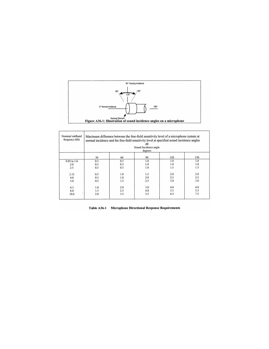
783
Federal Aviation Administration, DOT
Pt. 36, App. A
A36.3.6
Recording and reproducing systems.
A36.3.6.1 A recording and reproducing sys-
tem, such as a digital or analog magnetic
tape recorder, a computer-based system or
other permanent data storage device, must
be used to store sound pressure signals for
subsequent analysis. The sound produced by
the aircraft must be recorded in such a way
that a record of the complete acoustical sig-
nal is retained. The recording and reproduc-
ing systems must meet the specifications in
sections A36.3.6.2 to A36.3.6.9 at the recording
speeds and/or data sampling rates used for
the noise certification tests. Conformance
must be demonstrated for the frequency
bandwidths and recording channels selected
for the tests.
A36.3.6.2 The recording and reproducing
systems must be calibrated as described in
section A36.3.9.
(a) For aircraft noise signals for which the
high frequency spectral levels decrease rap-
idly with increasing frequency, appropriate
pre-emphasis and complementary de-empha-
sis networks may be included in the meas-
urement system. If pre-emphasis is included,
over the range of nominal one-third octave
midband frequencies from 800 Hz to 10 kHz
inclusive, the electrical gain provided by the
pre-emphasis network must not exceed 20 dB
relative to the gain at 800 Hz.
A36.3.6.3 For steady sinusoidal electrical
signals applied to the input of the entire
measurement system including all parts of
the microphone system except the micro-
phone at a selected signal level within 5 dB
of that corresponding to the calibration
sound pressure level on the reference level
range, the time-average signal level indi-
cated by the readout device at any one-third
octave nominal midband frequency from 50
Hz to 10 kHz inclusive must be within
±
1.5 dB
of that at the calibration check frequency.
The frequency response of a measurement
system, which includes components that
convert analog signals to digital form, must
be within
±
0.3 dB of the response at 10 kHz
over the frequency range from 10 kHz to 11.2
kHz.
N
OTE
: Microphone extension cables as con-
figured in the field need not be included for
the frequency response determination. This
VerDate Sep<11>2014
09:06 Jun 28, 2024
Jkt 262046
PO 00000
Frm 00793
Fmt 8010
Sfmt 8002
Y:\SGML\262046.XXX
262046
ER08JY02.000</GPH>
jspears on DSK121TN23PROD with CFR

784
14 CFR Ch. I (1–1–24 Edition)
Pt. 36, App. A
allowance does not eliminate the require-
ment of including microphone extension ca-
bles when performing the pink noise record-
ing in section A36.3.9.5.
A36.3.6.4 For analog tape recordings, the
amplitude fluctuations of a 1 kHz sinusoidal
signal recorded within 5 dB of the level cor-
responding to the calibration sound pressure
level must not vary by more than
±
0.5 dB
throughout any reel of the type of magnetic
tape used. Conformance to this requirement
must be demonstrated using a device that
has time-averaging properties equivalent to
those of the spectrum analyzer.
A36.3.6.5 For all appropriate level ranges
and for steady sinusoidal electrical signals
applied to the input of the measurement sys-
tem, including all parts of the microphone
system except the microphone, at one-third-
octave nominal midband frequencies of 50
Hz, 1 kHz and 10 kHz, and the calibration
check frequency, if it is not one of these fre-
quencies, the level non-linearity must not
exceed
±
0.5 dB for a linear operating range of
at least 50 dB below the upper boundary of
the level range.
N
OTE
1: Level linearity of measurement
system components may be tested according
to the methods described in IEC 61265 as
amended.
N
OTE
2: Microphone extension cables con-
figured in the field need not be included for
the level linearity determination.
A36.3.6.6 On the reference level range, the
level corresonding to the calibration sound
pressure level must be at least 5 dB, but no
more than 30 dB less than the upper bound-
ary of the level range.
A36.3.6.7 The linear operating ranges on ad-
jacent level ranges must overlap by at least
50 dB minus the change in attenuation intro-
duced by a change in the level range con-
trols.
N
OTE
: It is possible for a measurement sys-
tem to have level range controls that permit
attenuation changes of either 10 dB or 1 dB,
for example. With 10 dB steps, the minimum
overlap required would be 40 dB, and with 1
dB steps the minimum overlap would be 49
dB.
A36.3.6.8 An overload indicator must be in-
cluded in the recording and reproducing sys-
tems so that an overload indication will
occur during an overload condition on any
relevant level range.
A36.3.6.9 Attenuators included in the meas-
urement system to permit range changes
must operate in known intervals of decibel
steps.
A36.3.7
Analysis systems.
A36.3.7.1 The analysis system must con-
form to the specifications in sections
A36.3.7.2 to A36.3.7.7 for the frequency
bandwidths, channel configurations and gain
settings used for analysis.
A36.3.7.2 The output of the analysis system
must consist of one-third octave band sound
pressure levels as a function of time, ob-
tained by processing the noise signals (pref-
erably recorded) through an analysis system
with the following characteristics:
(a) A set of 24 one-third octave band filters,
or their equivalent, having nominal midband
frequencies from 50 Hz to 10 kHz inclusive;
(b) Response and averaging properties in
which, in principle, the output from any one-
third octave filter band is squared, averaged
and displayed or stored as time-averaged
sound pressure levels;
(c) The interval between successive sound
pressure level samples must be 500 ms
±
5 mil-
liseconds(ms) for spectral analysis with or
without slow time-weighting, as defined in
section A36.3.7.4;
(d) For those analysis systems that do not
process the sound pressure signals during the
period of time required for readout and/or re-
setting of the analyzer, the loss of data must
not exceed a duration of 5 ms; and
(e) The analysis system must operate in
real time from 50 Hz through at least 12 kHz
inclusive. This requirement applies to all op-
erating channels of a multi-channel spectral
analysis system.
A36.3.7.3 The minimum standard for the
one-third octave band analysis system is the
class 2 electrical performance requirements
of IEC 61260 as amended, over the range of
one-third octave nominal midband fre-
quencies from 50 Hz through 10 kHz inclusive
(incorporated by reference, see § 36.6).
N
OTE
: IEC 61260 specifies procedures for
testing of one-third octave band analysis
systems for relative attenuation, anti-
aliasing filters, real time operation, level
linearity, and filter integrated response (ef-
fective bandwidth).
A36.3.7.4 When slow time averaging is per-
formed in the analyzer, the response of the
one-third octave band analysis system to a
sudden onset or interruption of a constant
sinusoidal signal at the respective one-third
octave nominal midband frequency, must be
measured at sampling instants 0.5, 1, 1.5 and
2 seconds(s) after the onset and 0.5 and 1s
after interruption. The rising response must
be
¥
4
±
1 dB at 0.5s,
¥
1.75
±
0.75 dB at 1s,
¥
1
±
0.5 dB at 1.5s and
¥
0.5
±
0.5 dB at 2s relative
to the steady-state level. The falling re-
sponse must be such that the sum of the out-
put signal levels, relative to the initial
steady-state level, and the corresponding ris-
ing response reading is
¥
6.5
±
1 dB, at both 0.5
and 1s. At subsequent times the sum of the
rising and falling responses must be
¥
7.5 dB
or less. This equates to an exponential aver-
aging process (slow time-weighting) with a
nominal 1s time constant (
i.e., 2s averaging
time).
A36.3.7.5 When the one-third octave band
sound pressure levels are determined from
VerDate Sep<11>2014
09:06 Jun 28, 2024
Jkt 262046
PO 00000
Frm 00794
Fmt 8010
Sfmt 8002
Y:\SGML\262046.XXX
262046
jspears on DSK121TN23PROD with CFR

785
Federal Aviation Administration, DOT
Pt. 36, App. A
the output of the analyzer without slow
time-weighting, slow time-weighting must
be simulated in the subsequent processing.
Simulated slow time-weighted sound pres-
sure levels can be obtained using a contin-
uous exponential averaging process by the
following equation:
L
s
(i,k) = 10 log [(0.60653) 10
0.1
Ls[i,
(
k
¥
1
)
]
+
(0.39347) 10
0.1 L
(
i, k
)
]
where L
s
(i,k) is the simulated slow time-
weighted sound pressure level and L(i,k)
is the as-measured 0.5s time average
sound pressure level determined from the
output of the analyzer for the k-th in-
stant of time and i-th one-third octave
band. For k = 1, the slow time-weighted
sound pressure L
s
[i, (k
¥
1 = 0)] on the
right hand side should be set to 0 dB. An
approximation of the continuous expo-
nential averaging is represented by the
following equation for a four sample
averaging process for k
≥
4:
L
s
(i,k) = 10 log [(0.13) 10
0.1 L[i,
(
k
¥
3
)
]
+ (0.21) 10
0.1
L[i,
(
k
¥
2
)
]
+ (0.27) 10
0.1 L[i,
(
k
¥
1
)
]
+ (0.39) 10
0.1 L[i,
k]
]
where L
s
(i, k) is the simulated slow time-
weighted sound pressure level and L (i, k)
is the as measured 0.5s time average
sound pressure level determined from the
output of the analyzer for the k-th in-
stant of time and the i-th one-third oc-
tave band.
The sum of the weighting factors is 1.0 in
the two equations. Sound pressure levels cal-
culated by means of either equation are valid
for the sixth and subsequent 0.5s data sam-
ples, or for times greater than 2.5s after ini-
tiation of data analysis.
N
OTE
: The coefficients in the two equa-
tions were calculated for use in determining
equivalent slow time-weighted sound pres-
sure levels from samples of 0.5s time average
sound pressure levels. The equations do not
work with data samples where the averaging
time differs from 0.5s.
A36.3.7.6 The instant in time by which a
slow time-weighted sound pressure level is
characterized must be 0.75s earlier than the
actual readout time.
N
OTE
: The definition of this instant in
time is needed to correlate the recorded
noise with the aircraft position when the
noise was emitted and takes into account
the averaging period of the slow time-
weighting. For each 0.5 second data record
this instant in time may also be identified as
1.25 seconds after the start of the associated
2 second averaging period.
A36.3.7.7 The resolution of the sound pres-
sure levels, both displayed and stored, must
be 0.1 dB or finer.
A36.3.8
Calibration systems.
A36.3.8.1 The acoustical sensitivity of the
measurement system must be determined
using a sound calibrator generating a known
sound pressure level at a known frequency.
The minimum standard for the sound cali-
brator is the class 1L requirements of IEC
60942 as amended (incorporated by reference,
see § 36.6).
A36.3.9
Calibration and checking of system.
A36.3.9.1 Calibration and checking of the
measurement system and its constituent
components must be carried out to the satis-
faction of the FAA by the methods specified
in sections A36.3.9.2 through A36.3.9.10. The
calibration adjustments, including those for
environmental effects on sound calibrator
output level, must be reported to the FAA
and applied to the measured one-third-oc-
tave sound pressure levels determined from
the output of the analyzer. Data collected
during an overload indication are invalid and
may not be used. If the overload condition
occurred during recording, the associated
test data are invalid, whereas if the overload
occurred during analysis, the analysis must
be repeated with reduced sensitivity to
eliminate the overload.
A36.3.9.2 The free-field frequency response
of the microphone system may be deter-
mined by use of an electrostatic actuator in
combination with manufacturer’s data or by
tests in an anechoic free-field facility. The
correction for frequency response must be
determined within 90 days of each test series.
The correction for non-uniform frequency re-
sponse of the microphone system must be re-
ported to the FAA and applied to the meas-
ured one-third octave band sound pressure
levels determined from the output of the an-
alyzer.
A36.3.9.3 When the angles of incidence of
sound emitted from the aircraft are within
±
30
°
of grazing incidence at the microphone
(see Figure A36–1), a single set of free-field
corrections based on grazing incidence is
considered sufficient for correction of direc-
tional response effects. For other cases, the
angle of incidence for each 0.5 second sample
must be determined and applied for the cor-
rection of incidence effects.
A36.3.9.4 For analog magnetic tape record-
ers, each reel of magnetic tape must carry at
least 30 seconds of pink random or pseudo-
random noise at its beginning and end. Data
obtained from analog tape-recorded signals
will be accepted as reliable only if level dif-
ferences in the 10 kHz one-third-octave-band
are not more than 0.75 dB for the signals re-
corded at the beginning and end.
A36.3.9.5 The frequency response of the en-
tire measurement system while deployed in
the field during the test series, exclusive of
the microphone, must be determined at a
level within 5 dB of the level corresponding
to the calibration sound pressure level on
the level range used during the tests for each
one-third octave nominal midband frequency
from 50 Hz to 10 kHz inclusive, utilizing pink
random or pseudo-random noise. Within six
months of each test series the output of the
VerDate Sep<11>2014
09:06 Jun 28, 2024
Jkt 262046
PO 00000
Frm 00795
Fmt 8010
Sfmt 8002
Y:\SGML\262046.XXX
262046
jspears on DSK121TN23PROD with CFR

786
14 CFR Ch. I (1–1–24 Edition)
Pt. 36, App. A
noise generator must be determined by a
method traceable to the U.S. National Insti-
tute of Standards and Technology or to an
equivalent national standards laboratory as
determined by the FAA. Changes in the rel-
ative output from the previous calibration at
each one-third octave band may not exceed
0.2 dB. The correction for frequency response
must be reported to the FAA and applied to
the measured one-third octave sound pres-
sure levels determined from the output of
the analyzer.
A36.3.9.6 The performance of switched at-
tenuators in the equipment used during
noise certification measurements and cali-
bration must be checked within six months
of each test series to ensure that the max-
imum error does not exceed 0.1 dB.
A36.3.9.7 The sound pressure level produced
in the cavity of the coupler of the sound cali-
brator must be calculated for the test envi-
ronmental conditions using the manufactur-
er’s supplied information on the influence of
atmospheric air pressure and temperature.
This sound pressure level is used to establish
the acoustical sensitivity of the measure-
ment system. Within six months of each test
series the output of the sound calibrator
must be determined by a method traceable
to the U.S. National Institute of Standards
and Technology or to an equivalent national
standards laboratory as determined by the
FAA. Changes in output from the previous
calibration must not exceed 0.2 dB.
A36.3.9.8 Sufficient sound pressure level
calibrations must be made during each test
day to ensure that the acoustical sensitivity
of the measurement system is known at the
prevailing environmental conditions cor-
responding with each test series. The dif-
ference between the acoustical sensitivity
levels recorded immediately before and im-
mediately after each test series on each day
may not exceed 0.5 dB. The 0.5 dB limit ap-
plies after any atmospheric pressure correc-
tions have been determined for the cali-
brator output level. The arithmetic mean of
the before and after measurements must be
used to represent the acoustical sensitivity
level of the measurement system for that
test series. The calibration corrections must
be reported to the FAA and applied to the
measured one-third octave band sound pres-
sure levels determined from the output of
the analyzer.
A36.3.9.9 Each recording medium, such as a
reel, cartridge, cassette, or diskette, must
carry a sound pressure level calibration of at
least 10 seconds duration at its beginning
and end.
A36.3.9.10 The free-field insertion loss of
the windscreen for each one-third octave
nominal midband frequency from 50 Hz to 10
kHz inclusive must be determined with si-
nusoidal sound signals at the incidence an-
gles determined to be applicable for correc-
tion of directional response effects per sec-
tion A36.3.9.3. The interval between angles
tested must not exceed 30 degrees. For a
windscreen that is undamaged and
uncontaminated, the insertion loss may be
taken from manufacturer’s data. Alter-
natively, within six months of each test se-
ries the insertion loss of the windscreen may
be determined by a method traceable to the
U.S. National Institute of Standards and
Technology or an equivalent national stand-
ards laboratory as determined by the FAA.
Changes in the insertion loss from the pre-
vious calibration at each one-third-octave
frequency band must not exceed 0.4 dB. The
correction for the free-field insertion loss of
the windscreen must be reported to the FAA
and applied to the measured one-third octave
sound pressure levels determined from the
output of the analyzer.
A36.3.10 Adjustments for ambient noise.
A36.3.10.1 Ambient noise, including both an
acoustical background and electrical noise of
the measurement system, must be recorded
for at least 10 seconds at the measurement
points with the system gain set at the levels
used for the aircraft noise measurements.
Ambient noise must be representative of the
acoustical background that exists during the
flyover test run. The recorded aircraft noise
data is acceptable only if the ambient noise
levels, when analyzed in the same way, and
quoted in PNL (see A36.4.1.3 (a)), are at least
20 dB below the maximum PNL of the air-
craft.
A36.3.10.2 Aircraft sound pressure levels
within the 10 dB-down points (see A36.4.5.1)
must exceed the mean ambient noise levels
determined in section A36.3.10.1 by at least 3
dB in each one-third octave band, or must be
adjusted using a method approved by the
FAA; one method is described in the current
advisory circular for this part.
Section A36.4 Calculation of Effective Perceived
Noise Level From Measured Data
A36.4.1
General.
A36.4.1.1 The basic element for noise cer-
tification criteria is the noise evaluation
measure known as effective perceived noise
level, EPNL, in units of EPNdB, which is a
single number evaluator of the subjective ef-
fects of airplane noise on human beings.
EPNL consists of instantaneous perceived
noise level, PNL, corrected for spectral
irregularities, and for duration. The spectral
irregularity correction, called ‘‘tone correc-
tion factor’’, is made at each time increment
for only the maximum tone.
A36.4.1.2 Three basic physical properties of
sound pressure must be measured: level, fre-
quency distribution, and time variation. To
determine EPNL, the instantaneous sound
pressure level in each of the 24 one-third oc-
tave bands is required for each 0.5 second in-
crement of time during the airplane noise
measurement.
VerDate Sep<11>2014
09:06 Jun 28, 2024
Jkt 262046
PO 00000
Frm 00796
Fmt 8010
Sfmt 8002
Y:\SGML\262046.XXX
262046
jspears on DSK121TN23PROD with CFR

787
Federal Aviation Administration, DOT
Pt. 36, App. A
A36.4.1.3 The calculation procedure that
uses physical measurements of noise to de-
rive the EPNL evaluation measure of subjec-
tive response consists of the following five
steps:
(a) The 24 one-third octave bands of sound
pressure level are converted to perceived
noisiness (noy) using the method described
in section A36.4.2.1 (a). The noy values are
combined and then converted to instanta-
neous perceived noise levels, PNL(k).
(b) A tone correction factor C(k) is cal-
culated for each spectrum to account for the
subjective response to the presence of spec-
tral irregularities.
(c) The tone correction factor is added to
the perceived noise level to obtain tone-cor-
rected perceived noise levels PNLT(k), at
each one-half second increment:
PNLT(k) = PNL(k) + C(k)
The instantaneous values of tone-corrected
perceived noise level are derived and the
maximum value, PNLTM, is determined.
(d) A duration correction factor, D, is com-
puted by integration under the curve of tone-
corrected perceived noise level versus time.
(e) Effective perceived noise level, EPNL,
is determined by the algebraic sum of the
maximum tone-corrected perceived noise
level and the duration correction factor:
EPNL = PNLTM + D
A36.4.2
Perceived noise level.
A36.4.2.1 Instantaneous perceived noise lev-
els, PNL(k), must be calculated from instan-
taneous one-third octave band sound pres-
sure levels, SPL(i, k) as follows:
(a) Step 1: For each one-third octave band
from 50 through 10,000 Hz, convert SPL(i, k)
to perceived noisiness n(i, k), by using the
mathematical formulation of the noy table
given in section A36.4.7.
(b) Step 2: Combine the perceived noisiness
values, n(i, k), determined in step 1 by using
the following formula:
N (k)
n (k) +
n (i, k)
( , )
=
⎡
⎣
⎢
⎤
⎦
⎥ −
⎧
⎨
⎪
⎩⎪
⎫
⎬
⎪
⎭⎪
=
+
=
=
∑
∑
0 15
0 85
0 15
1
24
1
24
.
( )
.
( )
.
i
i
n k
n k
n i k
where n(k) is the largest of the 24 values of
n(i, k) and N(k) is the total perceived
noisiness.
(c) Step 3: Convert the total perceived
noisiness, N(k), determined in Step 2 into
perceived noise level, PNL(k), using the fol-
lowing formula:
PNL (k) = 40.0 +
10
log
log N (k)
2
N
OTE
: PNL(k) is plotted in the current ad-
visory circular for this part.
A36.4.3
Correction for spectral irregularities.
A36.4.3.1 Noise having pronounced spectral
irregularities (for example, the maximum
discrete frequency components or tones)
must be adjusted by the correction factor
C(k) calculated as follows:
(a) Step 1: After applying the corrections
specified under section A36.3.9, start with the
sound pressure level in the 80 Hz one-third
octave band (band number 3), calculate the
changes in sound pressure level (or ‘‘slopes’’)
in the remainder of the one-third octave
bands as follows:
s(3,k) = no value
s(4,
k) = SPL(4,k)
¥
SPL(3,
k)
•
•
s(
i,k) = SPL(i,k)
¥
SPL(
i
¥
1,
k)
•
•
s(24,
k) = SPL(24,k)
¥
SPL(23,
k)
(b) Step 2: Encircle the value of the slope,
s(i, k), where the absolute value of the
change in slope is greater than five; that is
where:
|
D
s(i,k)
|
=
|
s(i,k)
¥
s(i
¥
1,
k)
|
>5
(c) Step 3:
(1) If the encircled value of the slope s(i, k)
is positive and algebraically greater than the
slope s(i
¥
1, k) encircle SPL(i, k).
(2) If the encircled value of the slope s(i, k)
is zero or negative and the slope s(i
¥
1, k) is
positive, encircle SPL(i
¥
1, k).
(3) For all other cases, no sound pressure
level value is to be encircled.
(d) Step 4: Compute new adjusted sound
pressure levels SPL
′
(i, k) as follows:
(1) For non-encircled sound pressure levels,
set the new sound pressure levels equal to
the original sound pressure levels, SPL
′
(i, k)
= SPL(i, k).
(2) For encircled sound pressure levels in
bands 1 through 23 inclusive, set the new
sound pressure level equal to the arithmetic
average of the preceding and following sound
pressure levels as shown below:
SPL
′
(
i,k) =
1
⁄
2
[SPL(
i
¥
1,
k) + SPL(i + 1,k)]
(3) If the sound pressure level in the high-
est frequency band (i = 24) is encircled, set
the new sound pressure level in that band
equal to:
SPL
′
(24,
k) = SPL(23,k) + s(23,k)
(e) Step 5: Recompute new slope s
′
(i, k), in-
cluding one for an imaginary 25th band, as
follows:
s
′
(3,
k) = s
′
(4,
k)
s
′
(4,
k) = SPL
′
(4,
k)
¥
SPL
′
(3,
k)
•
•
s
′
(
i,k) = SPL
′
(
i,k)
¥
SPL
′
(
i
¥
1,
k)
•
•
VerDate Sep<11>2014
09:06 Jun 28, 2024
Jkt 262046
PO 00000
Frm 00797
Fmt 8010
Sfmt 8002
Y:\SGML\262046.XXX
262046
ER08JY02.001</MATH>
ER08JY02.002</MATH>
jspears on DSK121TN23PROD with CFR

788
14 CFR Ch. I (1–1–24 Edition)
Pt. 36, App. A
s
′
(24,
k) = SPL
′
(24,
k)
¥
SPL
′
(23,
k)
s
′
(25,
k) = s
′
(24,
k)
(f) Step 6: For i, from 3 through 23, com-
pute the arithmetic average of the three ad-
jacent slopes as follows:
s¯(i,k) =
1
⁄
3
[
s
′
(
i,k) + s
′
(
i + 1,k) + s
′
(
i + 2,k)]
(g) Step 7: Compute final one-third octave-
band sound pressure levels, SPL
′
(i,k), by be-
ginning with band number 3 and proceeding
to band number 24 as follows:
SPL
′
(3,
k) = SPL(3,k)
SPL
′
(4,
k) = SPL
′
(3,k) +
s¯(3,k)
•
•
SPL
′
(
i,k) = SPL
′
(i
¥
1,k) +
s¯(i
¥
1,k)
•
•
SPL
′
(24,
k) = SPL
′
(23,k) +
s¯(23,k)
(h) Setp 8: Calculate the differences, F
(i,k), between the original sound pressure
level and the final background sound pres-
sure level as follows:
F(i,k) = SPL(i,k)-SPL
′
(
i,k)
and note only values equal to or greater than
1.5.
(i) Step 9: For each of the relevant one-
third octave bands (3 through 24), determine
tone correction factors from the sound pres-
sure level differences F (i, k) and Table A36–
2.
VerDate Sep<11>2014
09:06 Jun 28, 2024
Jkt 262046
PO 00000
Frm 00798
Fmt 8010
Sfmt 8002
Y:\SGML\262046.XXX
262046
jspears on DSK121TN23PROD with CFR
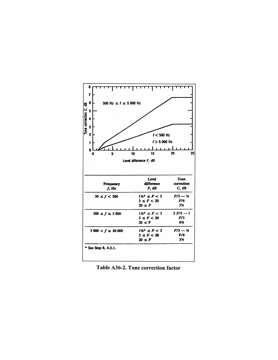
789
Federal Aviation Administration, DOT
Pt. 36, App. A
(j) Step 10: Designate the largest of the
tone correction factors, determined in Step
9, as C(k). (An example of the tone correction
procedure is given in the current advisory
circular for this part). Tone-corrected per-
ceived noise levels PNLT(k) must be deter-
mined by adding the C(k) values to cor-
responding PNL(k) values, that is:
PNLT(
k) = PNL(k) + C(k)
For any i-th one-third octave band, at any k-
th increment of time, for which the tone cor-
rection factor is suspected to result from
something other than (or in addition to) an
actual tone (or any spectral irregularity
other than airplane noise), an additional
analysis may be made using a filter with a
bandwidth narrower than one-third of an oc-
tave. If the narrow band analysis corrobo-
rates these suspicions, then a revised value
for the background sound pressure level
VerDate Sep<11>2014
09:06 Jun 28, 2024
Jkt 262046
PO 00000
Frm 00799
Fmt 8010
Sfmt 8003
Y:\SGML\262046.XXX
262046
ER08JY02.003</GPH>
jspears on DSK121TN23PROD with CFR
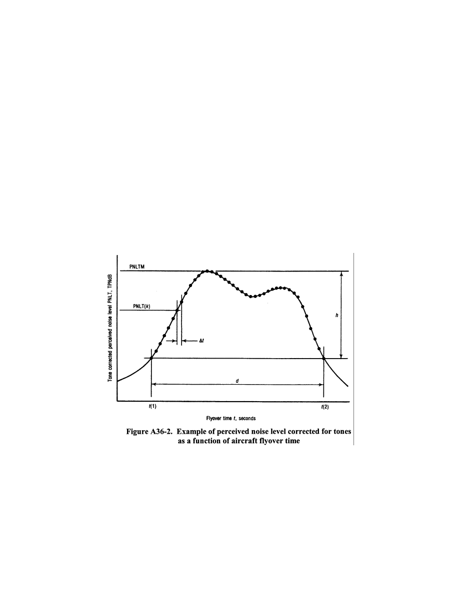
790
14 CFR Ch. I (1–1–24 Edition)
Pt. 36, App. A
SPL
′
(i,k), may be determined from the nar-
row band analysis and used to compute a re-
vised tone correction factor for that par-
ticular one-third octave band. Other methods
of rejecting spurious tone corrections may be
approved.
A36.4.3.2 The tone correction procedure
will underestimate EPNL if an important
tone is of a frequency such that it is re-
corded in two adjacent one-third octave
bands. An applicant must demonstrate that
either:
(a) No important tones are recorded in two
adjacent one-third octave bands; or
(b) That if an important tone has occurred,
the tone correction has been adjusted to the
value it would have had if the tone had been
recorded fully in a single one-third octave
band.
A36.4.4 Maximum tone-corrected perceived
noise level
A36.4.4.1 The maximum tone-corrected per-
ceived noise level, PNLTM, must be the max-
imum calculated value of the tone-corrected
perceived noise level PNLT(k). It must be
calculated using the procedure of section
A36.4.3. To obtain a satisfactory noise time
history, measurements must be made at 0.5
second time intervals.
N
OTE
1: Figure A36–2 is an example of a fly-
over noise time history where the maximum
value is clearly indicated.
N
OTE
2: In the absence of a tone correction
factor, PNLTM would equal PNLM.
A36.4.4.2 After the value of PNLTM is ob-
tained, the frequency band for the largest
tone correction factor is identified for the
two preceding and two succeeding 500 ms
data samples. This is performed in order to
identity the possibility of tone suppression
at PNLTM by one-third octave band sharing
of that tone. If the value of the tone correc-
tion factor C(k) for PNLTM is less than the
average value of C(k) for the five consecutive
time intervals, the average value of C(k)
must be used to compute a new value for
PNLTM.
A36.4.5
Duration correction.
A36.4.5.1 The duration correction factor D
determined by the integration technique is
defined by the expression:
VerDate Sep<11>2014
09:06 Jun 28, 2024
Jkt 262046
PO 00000
Frm 00800
Fmt 8010
Sfmt 8002
Y:\SGML\262046.XXX
262046
ER08JY02.004</GPH>
jspears on DSK121TN23PROD with CFR

791
Federal Aviation Administration, DOT
Pt. 36, App. A
D
log
T
antilog
PNLT
10
t 1
=
⎛
⎝
⎞
⎠
⎡
⎣
⎢
⎢
⎤
⎦
⎥
⎥
−
( )
( )
∫
10
1
2
t
dt
PNLTM
where T is a normalizing time constant,
PNLTM is the maximum value of PNLT,
t(1) is the first point of time after which
PNLT becomes greater than PNLTM–10,
and t(2) is the point of time after which
PNLT remains constantly less than
PNLTM–10.
A36.4.5.2 Since PNLT is calculated from
measured values of sound pressure level
(SPL), there is no obvious equation for
PNLT as a function of time. Consequently,
the equation is to be rewritten with a sum-
mation sign instead of an integral sign as
follows:
D
10 log
1
T
t.antilog
PNLTM
d/ t
=
⎛
⎝
⎞
⎠
( )
⎡
⎣
⎢
⎤
⎦
⎥ −
=
∑
Δ
Δ
k
PNLT k
0
10
where
D
t is the length of the equal incre-
ments of time for which PNLT(k) is cal-
culated and d is the time interval to the
nearest 0.5s during which PNLT(k) re-
mains greater or equal to PNLTM–10.
A36.4.5.3 To obtain a satisfactory history of
the perceived noise level use one of the fol-
lowing:
(a) Half-Second time intervals for
D
t; or
(b) A shorter time interval with approved
limits and constants.
A36.4.5.4 The following values for T and
D
t
must be used in calculating D in the equa-
tion given in section A36.4.5.2:
T = 10 s, and
D
t = 0.5s (or the approved sampling time in-
terval).
Using these values, the equation for D be-
comes:
D = 10 log
antilog
PNLT k
10
PNLTM
2d
k
=
∑
( )
⎡
⎣
⎢
⎤
⎦
⎥ −
−
0
13
where d is the duration time defined by the
points corresponding to the values
PNLTM–10.
A36.4.5.5 If in using the procedures given in
section A36.4.5.2, the limits of PNLTM–10 fall
between the calculated PNLT(k) values (the
usual case), the PNLT(k) values defining the
limits of the duration interval must be cho-
sen from the PNLT(k) values closest to
PNLTM–10. For those cases with more than
one peak value of PNLT(k), the applicable
limits must be chosen to yield the largest
possible value for the duration time.
A36.4.6
Effective perceived noise level.
The total subjective effect of an airplane
noise event, designated effective perceived
noise level, EPNL, is equal to the algebraic
sum of the maximum value of the tone-cor-
rected perceived noise level, PNLTM, and
the duration correction D. That is:
EPNL = PNLTM + D
where PNLTM and D are calculated using
the procedures given in sections A36.4.2,
A36.4.3, A36.4.4. and A36.4.5.
A36.4.7
Mathematical formulation of noy ta-
bles.
A36.4.7.1 The relationship between sound
pressure level (SPL) and the logarithm of
perceived noisiness is illustrated in Figure
A36–3 and Table A36–3.
A36.4.7.2 The bases of the mathematical
formulation are:
(a) The slopes (M(b), M(c), M(d) and M(e))
of the straight lines;
(b) The intercepts (SPL(b) and SPL(c)) of
the lines on the SPL axis; and
(c) The coordinates of the discontinuities,
SPL(a) and log n(a); SPL(d) and log n =
¥
1.0;
and SPL(e) and log n = log (0.3).
A36.4.7.3 Calculate noy values using the
following equations:
(a)
SPL
≥
SPL (a)
n = antilog
{
(c)[SPL
¥
SPL(c)]
}
VerDate Sep<11>2014
09:06 Jun 28, 2024
Jkt 262046
PO 00000
Frm 00801
Fmt 8010
Sfmt 8002
Y:\SGML\262046.XXX
262046
ER08JY02.005</GPH>
ER08JY02.006</GPH>
ER08JY02.007</MATH>
jspears on DSK121TN23PROD with CFR
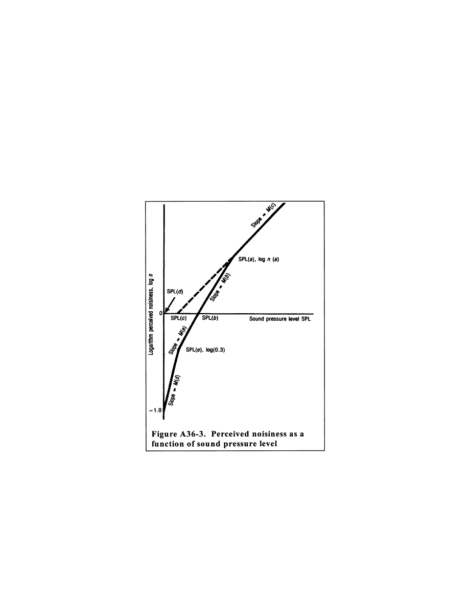
792
14 CFR Ch. I (1–1–24 Edition)
Pt. 36, App. A
(b)
SPL(b)
≤
SPL <SPL(a)
n = antilog
{
M(b)[SPL
¥
SPL(b)]
}
(c)
SPL(e)
≤
SPL <SPL(b)
n = 0.3 antilog
{
M(e)[SPL
¥
SPL(e)]
}
(d)
SPL(d)
≤
SPL <SPL(e)
n = 0.1 antilog
{
M(d)[SPL
¥
SPL(d)]
}
A36.4.7.4 Table A36–3 lists the values of the
constants necessary to calculate perceived
noisiness as a function of sound pressure
level.
VerDate Sep<11>2014
09:06 Jun 28, 2024
Jkt 262046
PO 00000
Frm 00802
Fmt 8010
Sfmt 8006
Y:\SGML\262046.XXX
262046
ER08JY02.008</GPH>
jspears on DSK121TN23PROD with CFR
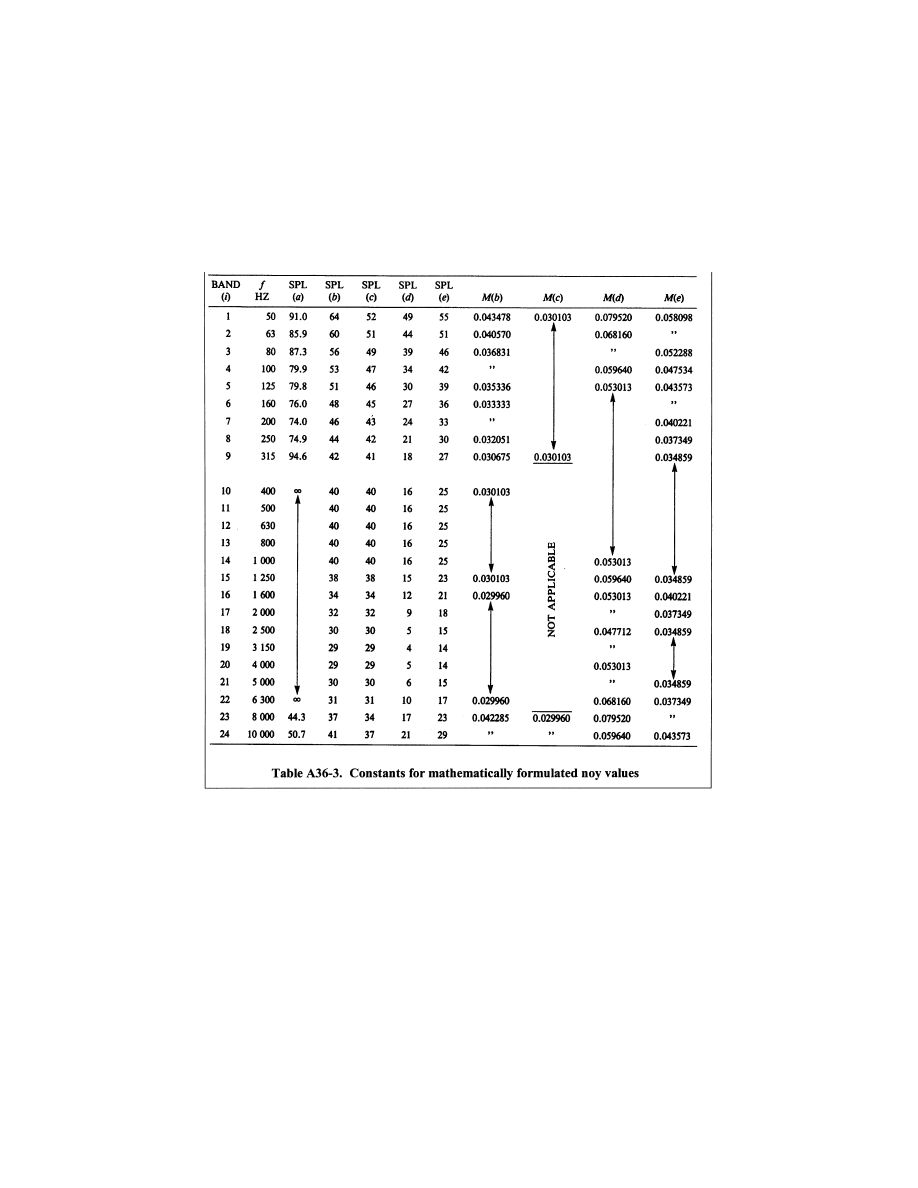
793
Federal Aviation Administration, DOT
Pt. 36, App. A
Section A36.5 Reporting of Data to the FAA
A36.5.1
General.
A36.5.1.1 Data representing physical meas-
urements and data used to make corrections
to physical measurements must be recorded
in an approved permanent form and ap-
pended to the record.
A36.5.1.2 All corrections must be reported
to and approved by the FAA, including cor-
rections to measurements for equipment re-
sponse deviations.
A36.5.1.3 Applicants may be required to
submit estimates of the individual errors in-
herent in each of the operations employed in
obtaining the final data.
A36.5.2
Data reporting.
An applicant is required to submit a noise
certification compliance report that includes
the following.
A36.5.2.1 The applicant must present meas-
ured and corrected sound pressure levels in
one-third octave band levels that are ob-
tained with equipment conforming to the
standards described in section A36.3 of this
appendix.
A36.5.2.2 The applicant must report the
make and model of equipment used for meas-
urement and analysis of all acoustic per-
formance and meteorological data.
A36.5.2.3 The applicant must report the fol-
lowing atmospheric environmental data, as
measured immediately before, after, or dur-
ing each test at the observation points pre-
scribed in section A36.2 of this appendix.
(a) Air temperature and relative humidity;
(b) Maximum, minimum and average wind
velocities; and
(c) Atmospheric pressure.
VerDate Sep<11>2014
09:06 Jun 28, 2024
Jkt 262046
PO 00000
Frm 00803
Fmt 8010
Sfmt 8002
Y:\SGML\262046.XXX
262046
ER08JY02.009</GPH>
jspears on DSK121TN23PROD with CFR
794
14 CFR Ch. I (1–1–24 Edition)
Pt. 36, App. A
A36.5.2.4 The applicant must report condi-
tions of local topography, ground cover, and
events that might interfere with sound re-
cordings.
A36.5.2.5 The applicant must report the fol-
lowing:
(a) Type, model and serial numbers (if any)
of airplane, engine(s), or propeller(s) (as ap-
plicable);
(b) Gross dimensions of airplane and loca-
tion of engines;
(c) Airplane gross weight for each test run
and center of gravity range for each series of
test runs;
(d) Airplane configuration such as flap, air-
brakes and landing gear positions for each
test run;
(e) Whether auxiliary power units (APU),
when fitted, are operating for each test run;
(f) Status of pneumatic engine bleeds and
engine power take-offs for each test run;
(g) Indicated airspeed in knots or kilo-
meters per hour for each test run;
(h) Engine performance data:
(1) For jet airplanes: engine performance in
terms of net thrust, engine pressure ratios,
jet exhaust temperatures and fan or com-
pressor shaft rotational speeds as determined
from airplane instruments and manufactur-
er’s data for each test run;
(2) For propeller-driven airplanes: engine
performance in terms of brake horsepower
and residual thrust; or equivalent shaft
horsepower; or engine torque and propeller
rotational speed; as determined from air-
plane instruments and manufacturer’s data
for each test run;
(i) Airplane flight path and ground speed
during each test run; and
(j) The applicant must report whether the
airplane has any modifications or non-stand-
ard equipment likely to affect the noise
characteristics of the airplane. The FAA
must approve any such modifications or non-
standard equipment.
A36.5.3
Reporting of noise certification ref-
erence conditions.
A36.5.3.1 Airplane position and perform-
ance data and the noise measurements must
be corrected to the noise certification ref-
erence conditions specified in the relevant
sections of appendix B of this part. The ap-
plicant must report these conditions, includ-
ing reference parameters, procedures and
configurations.
A36.5.4
Validity of results.
A36.5.4.1 Three average reference EPNL
values and their 90 percent confidence limits
must be produced from the test results and
reported, each such value being the arith-
metical average of the adjusted acoustical
measurements for all valid test runs at each
measurement point (flyover, lateral, or ap-
proach). If more than one acoustic measure-
ment system is used at any single measure-
ment location, the resulting data for each
test run must be averaged as a single meas-
urement. The calculation must be performed
by:
(a) Computing the arithmetic average for
each flight phase using the values from each
microphone point; and
(b) Computing the overall arithmetic aver-
age for each reference condition (flyover, lat-
eral or approach) using the values in para-
graph (a) of this section and the related 90
percent confidence limits.
A36.5.4.2 For each of the three certification
measuring points, the minimum sample size
is six. The sample size must be large enough
to establish statistically for each of the
three average noise certification levels a 90
percent confidence limit not exceeding
±
1.5
EPNdB. No test result may be omitted from
the averaging process unless approved by the
FAA.
N
OTE
: Permitted methods for calculating
the 90 percent confidence interval are shown
in the current advisory circular for this part.
A36.5.4.3 The average EPNL figures ob-
tained by the process described in section
A36.5.4.1 must be those by which the noise
performance of the airplane is assessed
against the noise certification criteria.
Section A36.6 Nomenclature: Symbols and Units
Symbol Unit
Meaning
antilog ..........
.....................
Antilogarithm to the base 10.
C(k) ..............
dB ................
Tone correction factor. The
factor to be added to
PNL(k) to account for the
presence of spectral irreg-
ularities such as tones at
the k-th increment of time.
d ...................
s ..................
Duration time. The time inter-
val between the limits of
t(1) and t(2) to the nearest
0.5 second.
D ..................
dB ................
Duration correction. The fac-
tor to be added to PNLTM
to account for the duration
of the noise.
EPNL ...........
EPNdB ........
Effective perceived noise
level. The value of PNL ad-
justed for both spectral
irregularities and duration of
the noise. (The unit EPNdB
is used instead of the unit
dB).
EPNL
r
..........
EPNdB ........
Effective perceived noise
level adjusted for reference
conditions.
f(i) ................
Hz ................
Frequency. The geometrical
mean frequency for the i-th
one-third octave band.
VerDate Sep<11>2014
09:06 Jun 28, 2024
Jkt 262046
PO 00000
Frm 00804
Fmt 8010
Sfmt 8002
Y:\SGML\262046.XXX
262046
jspears on DSK121TN23PROD with CFR
795
Federal Aviation Administration, DOT
Pt. 36, App. A
Symbol Unit
Meaning
F (i, k) ..........
dB ................
Delta-dB. The difference be-
tween the original sound
pressure level and the final
background sound pressure
level in the i-th one-third
octave band at the k-th in-
terval of time. In this case,
background sound pressure
level means the broadband
noise level that would be
present in the one-third oc-
tave band in the absence of
the tone.
h ...................
dB ................
dB-down. The value to be
subtracted from PNLTM
that defines the duration of
the noise.
H ..................
Percent ........
Relative humidity. The ambi-
ent atmospheric relative hu-
midity.
i ....................
.....................
Frequency band index. The
numerical indicator that de-
notes any one of the 24
one-third octave bands with
geometrical mean fre-
quencies from 50 to 10,000
Hz.
k ...................
.....................
Time increment index. The
numerical indicator that de-
notes the number of equal
time increments that have
elapsed from a reference
zero.
Log ...............
.....................
Logarithm to the base 10.
log n(a) ........
.....................
Noy discontinuity coordinate.
The log n value of the inter-
section point of the straight
lines representing the vari-
ation of SPL with log n.
M(b), M(c),
etc.
.....................
Noy inverse slope. The recip-
rocals of the slopes of
straight lines representing
the variation of SPL with
log n.
n ...................
noy ..............
The perceived noisiness at
any instant of time that oc-
curs in a specified fre-
quency range.
n(i,k) .............
noy ..............
The perceived noisiness at
the k-th instant of time that
occurs in the i-th one-third
octave band.
n(k) ..............
noy ..............
Maximum perceived noisi-
ness. The maximum value
of all of the 24 values of
n(i) that occurs at the k-th
instant of time.
N(k) ..............
noy ..............
Total perceived noisiness.
The total perceived noisi-
ness at the k-th instant of
time calculated from the 24-
instantaneous values of n
(i, k).
p(b), p(c), etc
.....................
Noy slope. The slopes of
straight lines representing
the variation of SPL with
log n.
PNL ..............
PNdB ...........
The perceived noise level at
any instant of time. (The
unit PNdB is used instead
of the unit dB).
Symbol Unit
Meaning
PNL(k) .........
PNdB ...........
The perceived noise level cal-
culated from the 24 values
of SPL (i, k), at the k-th in-
crement of time. (The unit
PNdB is used instead of
the unit dB).
PNLM ...........
PNdB ...........
Maximum perceived noise
level. The maximum value
of PNL(k). (The unit PNdB
is used instead of the unit
dB).
PNLT ...........
TPNdB .........
Tone-corrected perceived
noise level. The value of
PNL adjusted for the spec-
tral irregularities that occur
at any instant of time. (The
unit TPNdB is used instead
of the unit dB).
PNLT(k) .......
TPNdB .........
The tone-corrected perceived
noise level that occurs at
the k-th increment of time.
PNLT(k) is obtained by ad-
justing the value of PNL(k)
for the spectral irregularities
that occur at the k-th incre-
ment of time. (The unit
TPNdB is used instead of
the unit dB).
PNLTM ........
TPNdB .........
Maximum tone-corrected per-
ceived noise level. The
maximum value of PNLT(k).
(The unit TPNdB is used in-
stead of the unit dB).
PNLT
r
..........
TPNdB .........
Tone-corrected perceived
noise level adjusted for ref-
erence conditions.
s (i, k) ..........
dB ................
Slope of sound pressure
level. The change in level
between adjacent one-third
octave band sound pres-
sure levels at the i-th band
for the k-th instant of time.
D
s (i, k) ........
dB ................
Change in slope of sound
pressure level.
s
′
(i, k) .........
dB ................
Adjusted slope of sound pres-
sure level. The change in
level between adjacent ad-
justed one-third octave
band sound pressure levels
at the i-th band for the k-th
instant of time.
s¯ (i, k) ..........
dB ................
Average slope of sound pres-
sure level.
SPL ..............
dB re ...........
20
μ
Pa
Sound pressure level. The
sound pressure level that
occurs in a specified fre-
quency range at any instant
of time.
SPL(a) .........
dB re ...........
20
μ
Pa
Noy discontinuity coordinate.
The SPL value of the inter-
section point of the straight
lines representing the vari-
ation of SPL with log n.
SPL(b) .........
SPL (c)
dB re ...........
20
μ
Pa
Noy intercept. The intercepts
on the SPL-axis of the
straight lines representing
the variation of SPL with
log n.
SPL (i, k) .....
dB re ...........
20
μ
Pa
The sound pressure level at
the k-th instant of time that
occurs in the i-th one-third
octave band.
VerDate Sep<11>2014
09:06 Jun 28, 2024
Jkt 262046
PO 00000
Frm 00805
Fmt 8010
Sfmt 8002
Y:\SGML\262046.XXX
262046
jspears on DSK121TN23PROD with CFR
796
14 CFR Ch. I (1–1–24 Edition)
Pt. 36, App. A
Symbol Unit
Meaning
SPL
′
(i, k) ....
dB re ...........
20
μ
Pa
Adjusted sound pressure
level. The first approxima-
tion to background sound
pressure level in the i-th
one-third octave band for
the k-th instant of time.
SPL(i) ...........
dB re ...........
20
μ
Pa
Maximum sound pressure
level. The sound pressure
level that occurs in the i-th
one-third octave band of
the spectrum for PNLTM.
SPL(i)
r
..........
dB re ...........
20
μ
Pa
Corrected maximum sound
pressure level. The sound
pressure level that occurs
in the i-th one-third octave
band of the spectrum for
PNLTM corrected for at-
mospheric sound absorp-
tion.
SPL
′
(i, k) ....
dB re ...........
20
μ
Pa
Final background sound pres-
sure level. The second and
final approximation to back-
ground sound pressure
level in the i-th one-third
octave band for the k-th in-
stant of time.
t ....................
s ..................
Elapsed time. The length of
time measured from a ref-
erence zero.
t(1), t(2) ........
s ..................
Time limit. The beginning and
end, respectively, of the
noise time history defined
by h.
D
t .................
s ..................
Time increment. The equal in-
crements of time for which
PNL(k) and PNLT(k) are
calculated.
T ..................
s ..................
Normalizing time constant.
The length of time used as
a reference in the integra-
tion method for computing
duration corrections, where
T = 10s.
t(
°
F) (
°
C) ......
°
F,
°
C ..........
Temperature. The ambient air
temperature.
a
(i) ...............
dB/1000ft db/
100m.
Test atmospheric absorption.
The atmospheric attenu-
ation of sound that occurs
in the i-th one-third octave
band at the measured air
temperature and relative
humidity.
a
(i)
o
..............
dB/1000ft db/
100m.
Reference atmospheric ab-
sorption. The atmospheric
attenuation of sound that
occurs in the i-th one-third
octave band at a reference
air temperature and relative
humidity.
A
1
.................
Degrees .......
First constant climb angle
(Gear up, speed of at least
V
2
+ 10 kt (V
2
+ 19 km/h),
takeoff thrust).
A
2
.................
Degrees .......
Second constant climb angle
(Gear up, speed of at least
V
2
+ 10 kt (V
2
+ 19 km/h),
after cut-back).
d
...................
e
Degrees .......
Thrust cutback angles. The
angles defining the points
on the takeoff flight path at
which thrust reduction is
started and ended respec-
tively.
h
..................
Degrees .......
Approach angle.
Symbol Unit
Meaning
h
r
.................
Degrees .......
Reference approach angle.
q
...................
Degrees .......
Noise angle (relative to flight
path). The angle between
the flight path and noise
path. It is identical for both
measured and corrected
flight paths.
y
..................
Degrees .......
Noise angle (relative to
ground). The angle be-
tween the noise path and
the ground. It is identical for
both measured and cor-
rected flight paths.
μ
..................
.....................
Engine noise emission pa-
rameter.
μ
r
..................
.....................
Reference engine noise emis-
sion parameter.
D
1
.................
EPNdB ........
PNLT correction. The correc-
tion to be added to the
EPNL calculated from
measured data to account
for noise level changes due
to differences in atmos-
pheric absorption and noise
path length between ref-
erence and test conditions.
D
2
.................
EPNdB ........
Adjustment to duration correc-
tion. The adjustment to be
made to the EPNL cal-
culated from measured
data to account for noise
level changes due to the
noise duration between ref-
erence and test conditions.
D
3
.................
EPNdB ........
Source noise adjustment. The
adjustment to be made to
the EPNL calculated from
measured data to account
for noise level changes due
to differences between ref-
erence and test engine op-
erating conditions.
Section A36.7 Sound Attenuation in Air
A36.7.1 The atmospheric attenuation of
sound must be determined in accordance
with the procedure presented in section
A36.7.2.
A36.7.2 The relationship between sound at-
tenuation, frequency, temperature, and hu-
midity is expressed by the following equa-
tions.
A36.7.2(a) For calculations using the
English System of Units:
α
η δ
θ
θ
(i)
10
2.05 log
log
0
0
=
+
( )
×
(
)
+
×
−
[
]
( )
+
×
−
[
]
−
−
f
f
/
.33
.
.
.
1000
6
10
1 45325
4 6833 10
2 4215
4
3
10
and
δ
θ
θ
θ
=
( )
×
−
+
×
(
)
−
×
+
×
(
)
−
−
−
1010
10
10
1 97274664 2 288074 10
9 589 10
3 0 10
2
5 2
7 3
f 0
log H
.
.
.
.
VerDate Sep<11>2014
09:06 Jun 28, 2024
Jkt 262046
PO 00000
Frm 00806
Fmt 8010
Sfmt 8006
Y:\SGML\262046.XXX
262046
ER08JY02.010</MATH>
ER08JY02.011</MATH>
jspears on DSK121TN23PROD with CFR

797
Federal Aviation Administration, DOT
Pt. 36, App. A
where
h
(
d
) is listed in Table A36–4 and f
0
in Table
A36–5;
a
(i) is the attenuation coefficient in dB/1000
ft;
q
is the temperature in
°
F; and
H is the relative humidity, expressed as a
percentage.
A36.7.2(b) For calculations using the Inter-
national System of Units (SI):
α
η δ
θ
θ
i
log
0
0
( )
=
+
×
(
)
+
×
−
[
]
( )
+
×
−
[
]
−
−
10
10
2 05
1000
1 1394 10
1 916984
8 42994 10
2 755624
3
3
.
/
.
.
log
.
.
( )
f
f
and
δ
θ
θ
θ
=
1010
0
f
10
10
1
3 179768 10
2 173716 10
1 7496 10
2
4 2
6 3
log
.328924
.
.
.
H
−
+
×
(
)
−
×
+
×
(
)
−
−
−
×
where
h
(
d
) is listed in Table A36–4 and f
0
in Table
A36–5;
a
(i) is the attenuation coefficient in dB/100
m;
q
is the temperature in
°
C; and
H is the relative humidity, expressed as a
percentage.
A36.7.3 The values listed in table A36–4 are
to be used when calculating the equations
listed in section A36.7.2. A term of quadratic
interpolation is to be used where necessary.
Section A36.8 [Reserved]
VerDate Sep<11>2014
09:06 Jun 28, 2024
Jkt 262046
PO 00000
Frm 00807
Fmt 8010
Sfmt 8002
Y:\SGML\262046.XXX
262046
ER08JY02.012</MATH>
ER08JY02.013</MATH>
jspears on DSK121TN23PROD with CFR
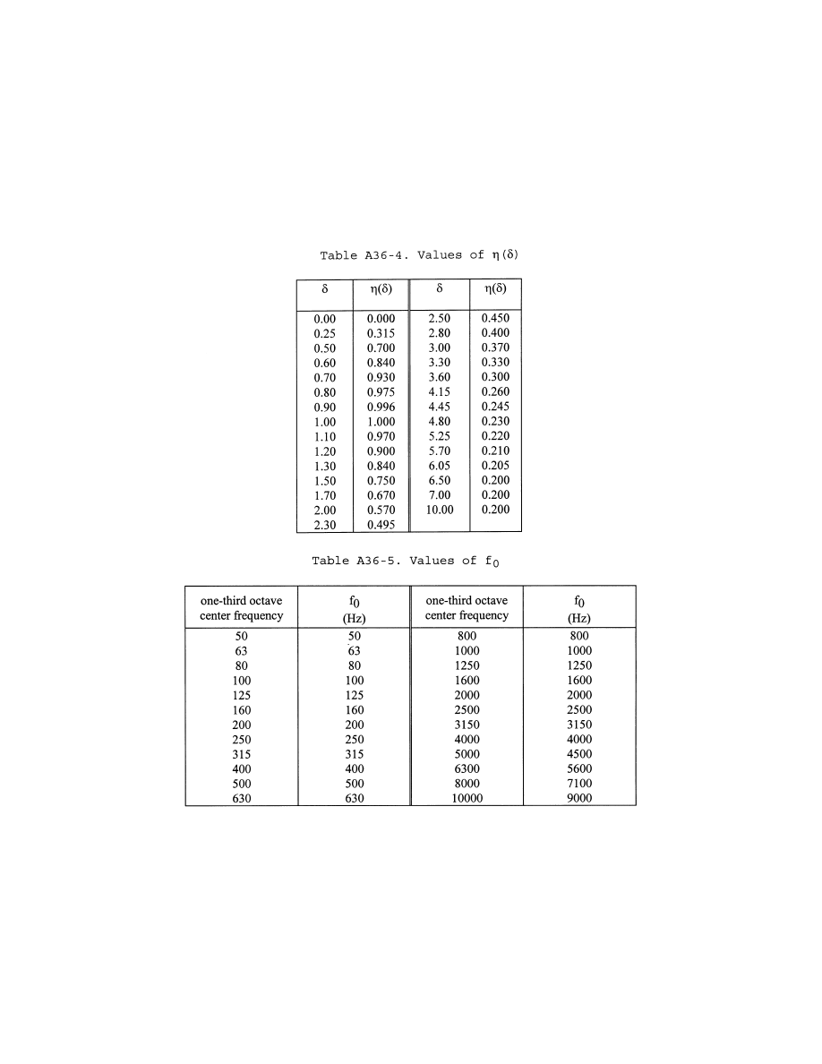
798
14 CFR Ch. I (1–1–24 Edition)
Pt. 36, App. A
Section A36.9 Adjustment of Airplane Flight
Test Results.
A36.9.1 When certification test conditions
are not identical to reference conditions, ap-
propriate adjustments must be made to the
measured noise data using the methods de-
scribed in this section.
A36.9.1.1 Adjustments to the measured
noise values must be made using one of the
methods described in sections A36.9.3 and
A36.9.4 for differences in the following:
(a) Attenuation of the noise along its path
as affected by ‘‘inverse square’’ and atmos-
pheric attenuation
(b) Duration of the noise as affected by the
distance and the speed of the airplane rel-
ative to the measuring point
VerDate Sep<11>2014
09:06 Jun 28, 2024
Jkt 262046
PO 00000
Frm 00808
Fmt 8010
Sfmt 8002
Y:\SGML\262046.XXX
262046
ER08JY02.014</MATH>
jspears on DSK121TN23PROD with CFR

799
Federal Aviation Administration, DOT
Pt. 36, App. A
(c) Source noise emitted by the engine as
affected by the differences between test and
reference engine operating conditions
(d) Airplane/engine source noise as affected
by differences between test and reference
airspeeds. In addition to the effect on dura-
tion, the effects of airspeed on component
noise sources must be accounted for as fol-
lows: for conventional airplane configura-
tions, when differences between test and ref-
erence airspeeds exceed 15 knots (28 km/h)
true airspeed, test data and/or analysis ap-
proved by the FAA must be used to quantify
the effects of the airspeed adjustment on re-
sulting certification noise levels.
A36.9.1.2 The ‘‘integrated’’ method of ad-
justment, described in section A36.9.4, must
be used on takeoff or approach under the fol-
lowing conditions:
(a) When the amount of the adjustment
(using the ‘‘simplified’’ method) is greater
than 8 dB on flyover, or 4 dB on approach; or
(b) When the resulting final EPNL value on
flyover or approach (using the simplified
method) is within 1 dB of the limiting noise
levels as prescribed in section B36.5 of this
part.
A36.9.2
Flight profiles.
As described below, flight profiles for both
test and reference conditions are defined by
their geometry relative to the ground, to-
gether with the associated airplane speed
relative to the ground, and the associated
engine control parameter(s) used for deter-
mining the noise emission of the airplane.
A36.9.2.1
Takeoff Profile.
N
OTE
: Figure A36–4 illustrates a typical
takeoff profile.
(a) The airplane begins the takeoff roll at
point A, lifts off at point B and begins its
first climb at a constant angle at point C.
Where thrust or power (as appropriate) cut-
back is used, it is started at point D and
completed at point E. From here, the air-
plane begins a second climb at a constant
angle up to point F, the end of the noise cer-
tification takeoff flight path.
(b) Position K
1
is the takeoff noise meas-
uring station and AK
1
is the distance from
start of roll to the flyover measuring point.
Position K
2
is the lateral noise measuring
station, which is located on a line parallel
to, and the specified distance from, the run-
way center line where the noise level during
takeoff is greatest.
(c) The distance AF is the distance over
which the airplane position is measured and
synchronized with the noise measurements,
as required by section A36.2.3.2 of this part.
A36.9.2.2
Approach Profile.
N
OTE
: Figure A36–5 illustrates a typical ap-
proach profile.
(a) The airplane begins its noise certifi-
cation approach flight path at point G and
touches down on the runway at point J, at a
distance OJ from the runway threshold.
(b) Position K
3
is the approach noise meas-
uring station and K
3
O is the distance from
the approach noise measurement point to
the runway threshold.
(c) The distance GI is the distance over
which the airplane position is measured and
synchronized with the noise measurements,
as required by section A36.2.3.2 of this part.
VerDate Sep<11>2014
09:06 Jun 28, 2024
Jkt 262046
PO 00000
Frm 00809
Fmt 8010
Sfmt 8002
Y:\SGML\262046.XXX
262046
jspears on DSK121TN23PROD with CFR
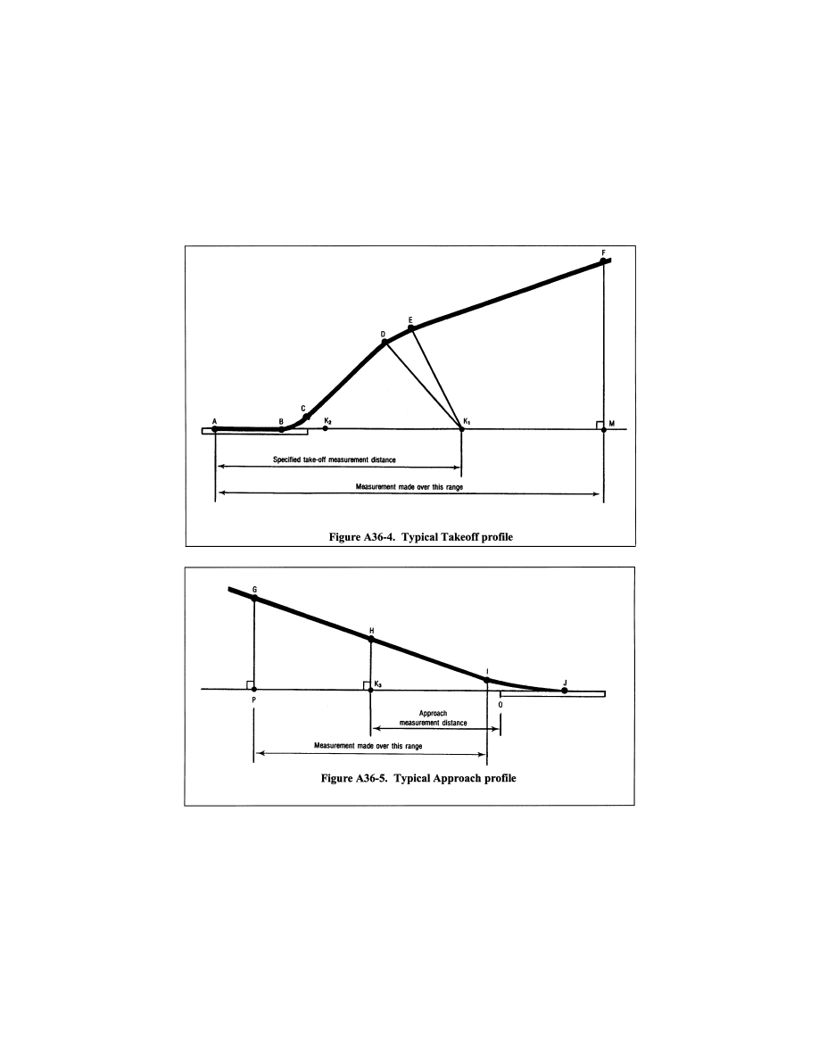
800
14 CFR Ch. I (1–1–24 Edition)
Pt. 36, App. A
The airplane reference point for approach
measurements is the instrument landing sys-
tem (ILS) antenna. If no ILS antenna is in-
stalled an alternative reference point must
be approved by the FAA.
A36.9.3
Simplified method of adjustment.
A36.9.3.1
General. As described below, the
simplified adjustment method consists of ap-
plying adjustments (to the EPNL, which is
calculated from the measured data) for the
differences between measured and reference
conditions at the moment of PNLTM.
A36.9.3.2
Adjustments to PNL and PNLT.
(a) The portions of the test flight path and
the reference flight path described below,
and illustrated in Figure A36–6, include the
noise time history that is relevant to the
calculation of flyover and approach EPNL.
In figure A36–6:
VerDate Sep<11>2014
09:06 Jun 28, 2024
Jkt 262046
PO 00000
Frm 00810
Fmt 8010
Sfmt 8002
Y:\SGML\262046.XXX
262046
ER08JY02.015</MATH>
jspears on DSK121TN23PROD with CFR
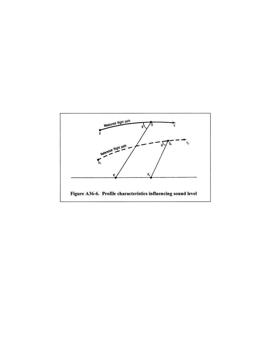
801
Federal Aviation Administration, DOT
Pt. 36, App. A
(1) XY represents the portion of the meas-
ured flight path that includes the noise time
history relevant to the calculation of flyover
and approach EPNL; X
r
Y
r
represents the cor-
responding portion of the reference flight
path.
(2) Q represents the airplane’s position on
the measured flight path at which the noise
was emitted and observed as PNLTM at the
noise measuring station K. Q
r
is the cor-
responding position on the reference flight
path, and K
r
the reference measuring station.
QK and Q
r
K
r
are, respectively, the measured
and reference noise propagation paths, Q
r
being determined from the assumption that
QK and Q
r
K
r
form the same angle
q
with their
respective flight paths.
(b) The portions of the test flight path and
the reference flight path described in para-
graph (b)(1) and (2), and illustrated in Figure
A36–7(a) and (b), include the noise time his-
tory that is relevant to the calculation of
lateral EPNL.
(1) In figure A36–7(a), XY represents the
portion of the measured flight path that in-
cludes the noise time history that is relevant
to the calculation of lateral EPNL; in figure
A36–7(b), X
r
Y
r
represents the corresponding
portion of the reference flight path.
(2) Q represents the airplane position on
the measured flight path at which the noise
was emitted and observed as PNLTM at the
noise measuring station K. Q
r
is the cor-
responding position on the reference flight
path, and K
r
the reference measuring station.
QK and Q
r
K
r
are, respectively, the measured
and reference noise propagation paths. In
this case K
r
is only specified as being on a
particular Lateral line; K
r
and Q
r
are there-
fore determined from the assumptions that
QK and Q
r
K
r
:
(i) Form the same angle
q
with their re-
spective flight paths; and
(ii) Form the same angle
y
with the
ground.
N
OTE
: For the lateral noise measurement,
sound propagation is affected not only by in-
verse square and atmospheric attenuation,
but also by ground absorption and reflection
effects which depend mainly on the angle
y
.
VerDate Sep<11>2014
09:06 Jun 28, 2024
Jkt 262046
PO 00000
Frm 00811
Fmt 8010
Sfmt 8002
Y:\SGML\262046.XXX
262046
ER08JY02.016</MATH>
jspears on DSK121TN23PROD with CFR
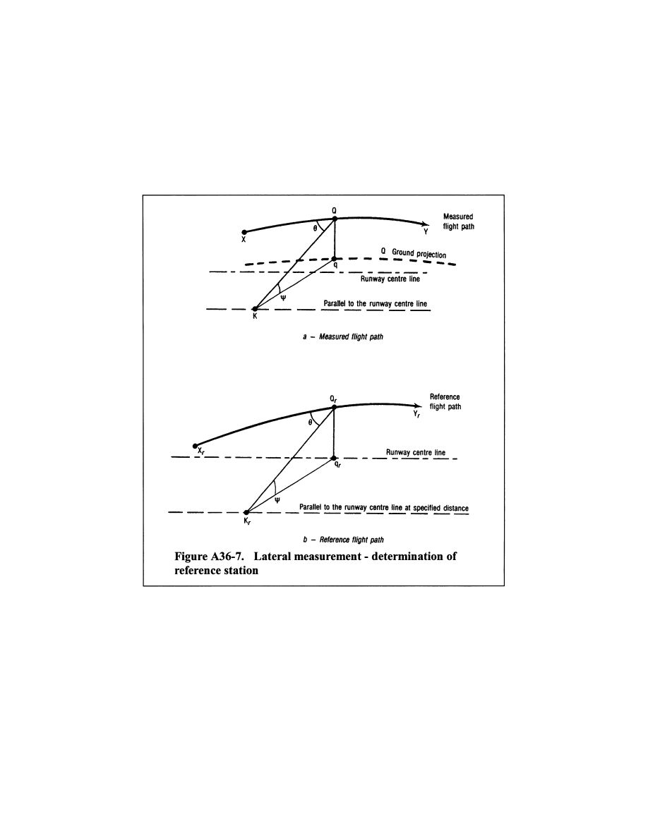
802
14 CFR Ch. I (1–1–24 Edition)
Pt. 36, App. A
A36.9.3.2.1 The one-third octave band levels
SPL(i) comprising PNL (the PNL at the mo-
ment of PNLTM observed at K) must be ad-
justed to reference levels SPL(i)
r
as follows:
A36.9.3.2.1(a) For calculations using the
English System of Units:
SPL(
i)
r
= SPL(
i) + 0.001[
a
(
i)
¥
a
(
i)
0
]QK
+ 0.001
a
(
i)
0
(QK
¥
Q
r
K
r
)
+ 20log(QK/Q
r
K
r
)
In this expression,
(1) The term 0.001[
a
(
i)
¥
a
(
i)
0
]QK is the ad-
justment for the effect of the change in
sound attenuation coefficient, and
a
(i) and
a
(i)
0
are the coefficients for the test and ref-
erence atmospheric conditions respectively,
determined under section A36.7 of this appen-
dix;
(2) The term 0.001
a
(i)
0
(QK
¥
Q
r
K
r
) is the ad-
justment for the effect of the change in the
noise path length on the sound attenuation;
(3) The term 20 log(QK/Q
r
K
r
) is the adjust-
ment for the effect of the change in the noise
path length due to the ‘‘inverse square’’ law;
(4) QK and Q
r
K
r
are measured in feet and
a
(i) and
a
(i)
0
are expressed in dB/1000 ft.
A36.9.3.2.1(b) For calculations using the
International System of Units:
SPL(i)
r
= SPL(i) + 0.01[
a
(i)
¥
a
(i)
0
]QK
+ 0.01
a
(i)
0
(QK
¥
Q
r
K
r
)
+ 20 log(QK/Q
r
K
r
)
In this expression,
VerDate Sep<11>2014
09:06 Jun 28, 2024
Jkt 262046
PO 00000
Frm 00812
Fmt 8010
Sfmt 8003
Y:\SGML\262046.XXX
262046
ER08JY02.017</MATH>
jspears on DSK121TN23PROD with CFR
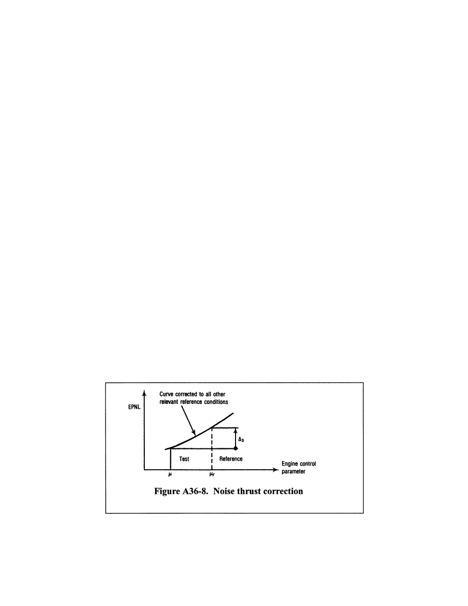
803
Federal Aviation Administration, DOT
Pt. 36, App. A
(1) The term 0.01[
a
(i)
¥
a
(i)
0
]QK is the ad-
justment for the effect of the change in
sound attenuation coefficient, and
a
(i) and
a
(i)
0
are the coefficients for the test and ref-
erence atmospheric conditions respectively,
determined under section A36.7 of this appen-
dix;
(2) The term 0.01
a
(i)
0
(QK
¥
Q
r
K
r
) is the ad-
justment for the effect of the change in the
noise path length on the sound attenuation;
(3) The term 20 log(QK/Q
r
K
r
) is the adjust-
ment for the effect of the change in the noise
path length due to the inverse square law;
(4) QK and Q
r
K
r
are measured in meters and
a
(i) and
a
(i)
0
are expressed in dB/100 m.
A36.9.3.2.1.1
PNLT Correction.
(a) Convert the corrected values, SPL(i)
r
,
to PNLT
r
;
(b) Calculate the correction term
D
1
using
the following equation:
D
1
= PNLT
r
¥
PNLTM
A36.9.3.2.1.2 Add
D
1
arithmetically to the
EPNL calculated from the measured data.
A36.9.3.2.2 If, during a test flight, several
peak values of PNLT that are within 2 dB of
PNLTM are observed, the procedure defined
in section A36.9.3.2.1 must be applied at each
peak, and the adjustment term, calculated
according to section A36.9.3.2.1, must be
added to each peak to give corresponding ad-
justed peak values of PNLT. If these peak
values exceed the value at the moment of
PNLTM, the maximum value of such exceed-
ance must be added as a further adjustment
to the EPNL calculated from the measured
data.
A36.9.3.3
Adjustments to duration correction.
A36.9.3.3.1 Whenever the measured flight
paths and/or the ground velocities of the test
conditions differ from the reference flight
paths and/or the ground velocities of the ref-
erence conditions, duration adjustments
must be applied to the EPNL values cal-
culated from the measured data. The adjust-
ments must be calculated as described below.
A36.9.3.3.2 For the flight path shown in Fig-
ure A36–6, the adjustment term is calculated
as follows:
D
2
=
¥
7.5 log(QK/Q
r
K
r
) + 10 log(V/V
r
)
(a) Add
D
2
arithmetically to the EPNL cal-
culated from the measured data.
A36.9.3.4
Source noise adjustments.
A36.9.3.4.1 To account for differences be-
tween the parameters affecting engine noise
as measured in the certification flight tests,
and those calculated or specified in the ref-
erence conditions, the source noise adjust-
ment must be calculated and applied. The
adjustment is determined from the manufac-
turer’s data approved by the FAA. Typical
data used for this adjustment are illustrated
in Figure A36–8 that shows a curve of EPNL
versus the engine control parameter
μ
, with
the EPNL data being corrected to all the
other relevant reference conditions (airplane
mass, speed and altitude, air temperature)
and for the difference in noise between the
test engine and the average engine (as de-
fined in section B36.7(b)(7)). A sufficient
number of data points over a range of values
of
μ
r
is required to calculate the source noise
adjustments for lateral, flyover and ap-
proach noise measurements.
A36.9.3.4.2 Calculate adjustment term
D
3
by
subtracting the EPNL value corresponding
to the parameter
μ
from the EPNL value cor-
responding to the parameter
μ
r
. Add
D
3
VerDate Sep<11>2014
09:06 Jun 28, 2024
Jkt 262046
PO 00000
Frm 00813
Fmt 8010
Sfmt 8002
Y:\SGML\262046.XXX
262046
ER08JY02.018</GPH>
jspears on DSK121TN23PROD with CFR
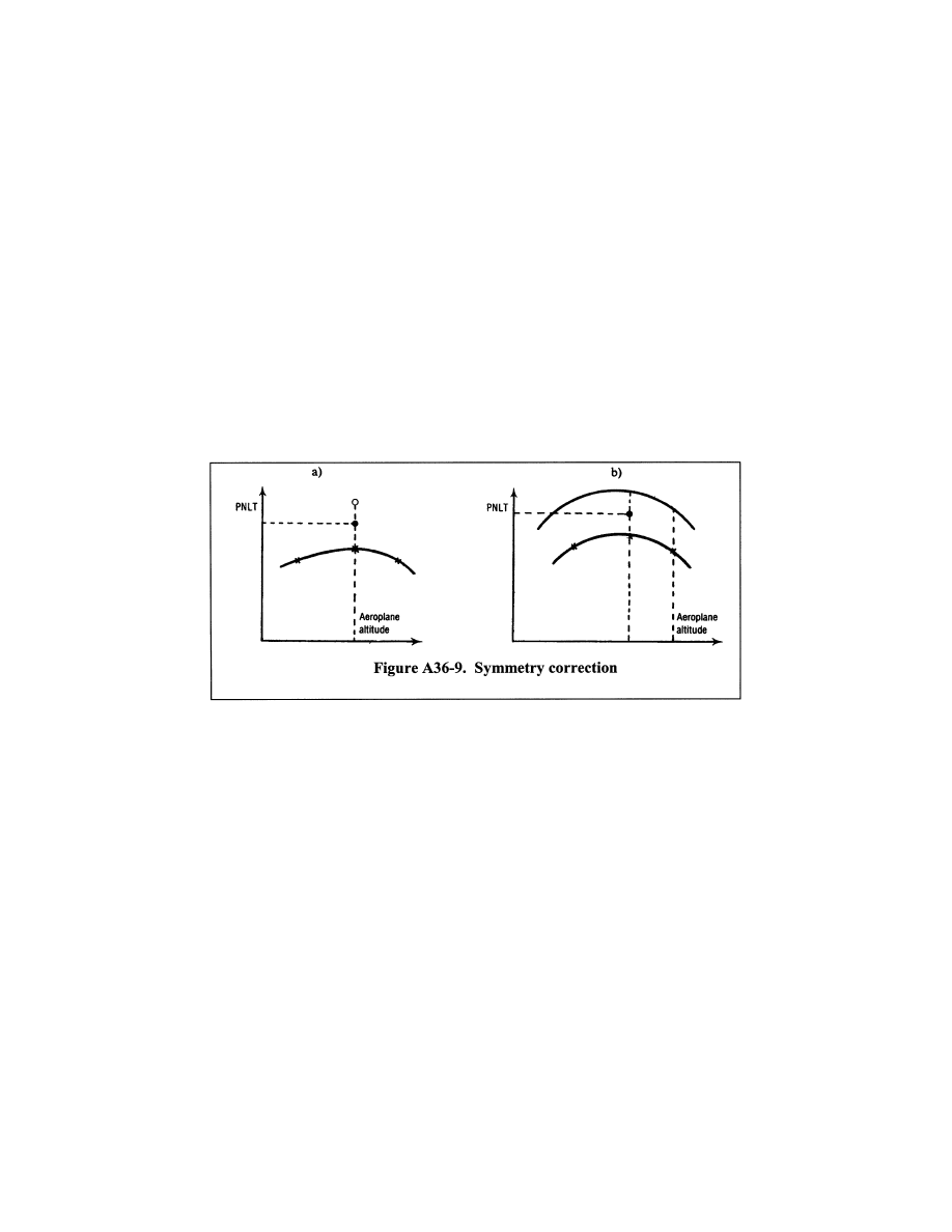
804
14 CFR Ch. I (1–1–24 Edition)
Pt. 36, App. A
arithmetically to the EPNL value calculated
from the measured data.
A36.9.3.5
Symmetry adjustments.
A36.9.3.5.1 A symmetry adjustment to each
lateral noise value (determined at the sec-
tion B36.4(b) measurement points), is to be
made as follows:
(a) If the symmetrical measurement point
is opposite the point where the highest noise
level is obtained on the main lateral meas-
urement line, the certification noise level is
the arithmetic mean of the noise levels
measured at these two points (see Figure
A36–9(a));
(b) If the condition described in paragraph
(a) of this section is not met, then it is as-
sumed that the variation of noise with the
altitude of the airplane is the same on both
sides; there is a constant difference between
the lines of noise versus altitude on both
sides (see figure A36–9(b)). The certification
noise level is the maximum value of the
mean between these lines.
A36.9.4
Integrated method of adjustment
A36.9.4.1
General. As described in this sec-
tion, the integrated adjustment method con-
sists of recomputing under reference condi-
tions points on the PNLT time history cor-
responding to measured points obtained dur-
ing the tests, and computing EPNL directly
for the new time history obtained in this
way. The main principles are described in
sections A36.9.4.2 through A36.9.4.4.1.
A36.9.4.2
PNLT computations.
(a) The portions of the test flight path and
the reference flight path described in para-
graph (a)(1) and (2), and illustrated in Figure
A36–10, include the noise time history that is
relevant to the calculation of flyover and ap-
proach EPNL. In figure A36–10:
VerDate Sep<11>2014
09:06 Jun 28, 2024
Jkt 262046
PO 00000
Frm 00814
Fmt 8010
Sfmt 8002
Y:\SGML\262046.XXX
262046
ER08JY02.019</GPH>
jspears on DSK121TN23PROD with CFR
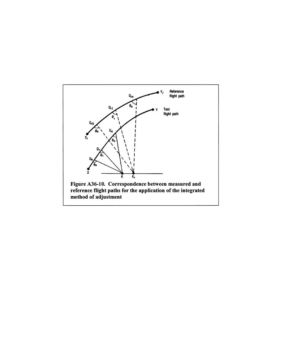
805
Federal Aviation Administration, DOT
Pt. 36, App. A
(1) XY represents the portion of the meas-
ured flight path that includes the noise time
history relevant to the calculation of flyover
and approach EPNL; X
r
Y
r
represents the cor-
responding reference flight path.
(2) The points Q
0
, Q
1
, Q
n
represent airplane
positions on the measured flight path at
time t
0
, t
1
and t
n
respectively. Point Q
1
is the
point at which the noise was emitted and ob-
served as one-third octave values SPL(i)
1
at
the noise measuring station K at time t
1
.
Point Q
r1
represents the corresponding posi-
tion on the reference flight path for noise ob-
served as SPL(i)
r1
at the reference measuring
station K
r
at time t
r1
. Q
1
K and Q
r1
K
r
are re-
spectively the measured and reference noise
propagation paths, which in each case form
the angle
q
1
with their respective flight
paths. Q
r0
and Q
rn
are similarly the points on
the reference flight path corresponding to Q
0
and Q
n
on the measured flight path. Q
0
and Q
n
are chosen so that between Q
r0
and Q
rn
all
values of PNLT
r
(computed as described in
paragraphs A36.9.4.2.2 and A36.9.4.2.3) within
10 dB of the peak value are included.
(b) The portions of the test flight path and
the reference flight path described in para-
graph (b)(1) and (2), and illustrated
in Figure
A36–11(a) and (b), include the noise time his-
tory that is relevant to the calculation of
lateral EPNL.
(1) In figure A36–11(a) XY represents the
portion of the measured flight path that in-
cludes the noise time history that is relevant
to the calculation of lateral EPNL; in figure
A36–11(b), X
r
Y
r
represents the corresponding
portion of the reference flight path.
(2) The points Q
0
, Q
1
and Q
n
represent air-
plane positions on the measured flight path
at time t
0
, t
1
and t
n
respectively. Point Q
1
is
the point at which the noise was emitted and
observed as one-third octave values SPL(i)
1
at the noise measuring station K at time t
1
.
The point Q
r1
represents the corresponding
position on the reference flight path for
noise observed as SPL(i)
r1
at the measuring
station K
r
at time t
r1
. Q
1
K and Q
r1
K
r
are re-
spectively the measured and reference noise
propagation paths. Q
r0
and Q
rn
are similarly
the points on the reference flight path cor-
responding to Q
0
and Q
n
on the measured
flight path.
VerDate Sep<11>2014
09:06 Jun 28, 2024
Jkt 262046
PO 00000
Frm 00815
Fmt 8010
Sfmt 8002
Y:\SGML\262046.XXX
262046
ER08jy02.020</GPH>
jspears on DSK121TN23PROD with CFR
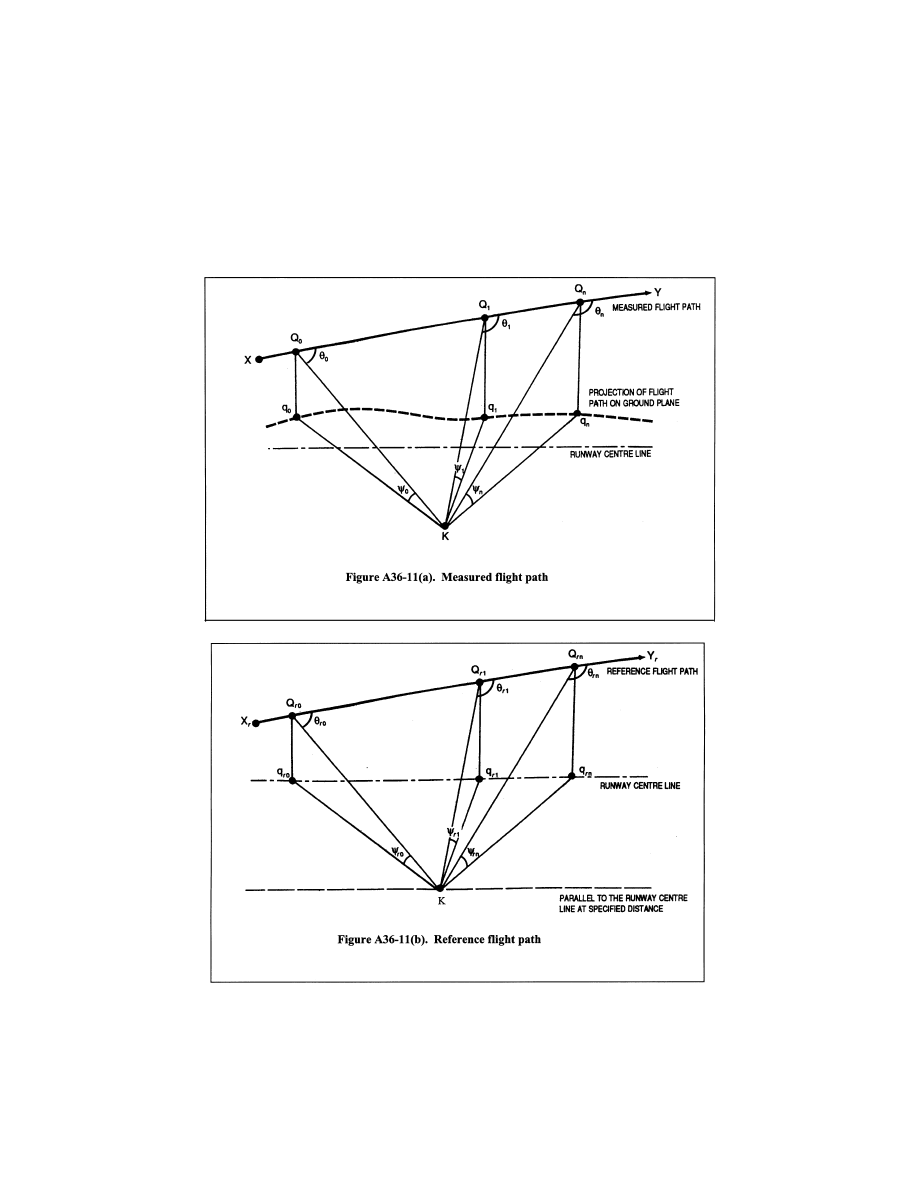
806
14 CFR Ch. I (1–1–24 Edition)
Pt. 36, App. A
Q
0
and Q
n
are chosen to that between Q
ro
and Q
rn
all values of PNLT
r
(computed as de-
scribed in paragraphs A36.9.4.2.2 and
A36.9.4.2.3) within 10 dB of the peak value are
included. In this case K
r
is only specified as
VerDate Sep<11>2014
09:06 Jun 28, 2024
Jkt 262046
PO 00000
Frm 00816
Fmt 8010
Sfmt 8002
Y:\SGML\262046.XXX
262046
ER08JY02.021</GPH>
jspears on DSK121TN23PROD with CFR
807
Federal Aviation Administration, DOT
Pt. 36, App. A
being on a particular lateral line. The posi-
tion of K
r
and Q
r1
are determined from the
following requirements.
(i) Q
1
K and Q
r1
K
r
form the same angle
q
1
with their respective flight paths; and
(ii) The differences between the angles
1
and
r1
must be minimized using a method, ap-
proved by the FAA. The differences between
the angles are minimized since, for geometri-
cal reasons, it is generally not possible to
choose K
r
so that the condition described in
paragraph A36.9.4.2(b)(2)(i) is met while at
the same time keeping
1
and
r1
equal.
N
OTE
: For the lateral noise measurement,
sound propagation is affected not only by
‘‘inverse square’’ and atmospheric attenu-
ation, but also by ground absorption and re-
flection effects which depend mainly on the
angle.
A36.9.4.2.1 In paragraphs A36.9.4.2(a)(2) and
(b)(2) the time t
r1
is later (for Q
r1
K
r
>Q
1
K)
than t
1
by two separate amounts:
(1) The time taken for the airplane to trav-
el the distance Q
r1
Q
r0
at a speed V
r
less the
time taken for it to travel Q
1
Q
0
at V;
(2) The time taken for sound to travel the
distance Q
r1
K
r
–Q
1
K.
N
OTE
: For the flight paths described in
paragraphs A36.9.4.2(a) and (b), the use of
thrust or power cut-back will result in test
and reference flight paths at full thrust or
power and at cut-back thrust or power.
Where the transient region between these
thrust or power levels affects the final re-
sult, an interpolation must be made between
them by an approved method such as that
given in the current advisory circular for
this part.
A36.9.4.2.2 The measured values of SPL(i)
1
must be adjusted to the reference values
SPL(i)
r1
to account for the differences be-
tween measured and reference noise path
lengths and between measured and reference
atmospheric conditions, using the methods
of section A36.9.3.2.1 of this appendix. A cor-
responding value of PNL
r1
must be computed
according to the method in section A36.4.2.
Values of PNL
r
must be computed for times
t
0
through t
n
.
A36.9.4.2.3 For each value of PNL
r1
, a tone
correction factor C
1
must be determined by
analyzing the reference values SPL(i)
r
using
the methods of section A36.4.3 of this appen-
dix, and added to PNL
r1
to yield PNLT
r1
.
Using the process described in this para-
graph, values of PNLT
r
must be computed for
times t
0
through t
n
.
A36.9.4.3
Duration correction.
A36.9.4.3.1 The values of PNLT
r
cor-
responding to those of PNLT at each one-
half second interval must be plotted against
time (PNLT
r1
at time t
r1
). The duration cor-
rection must then be determined using the
method of section A36.4.5.1 of this appendix,
to yield EPNL
r
.
A36.9.4.4
Source Noise Adjustment.
A36.9.4.4.1 A source noise adjustment,
D
3
,
must be determined using the methods of
section A36.9.3.4 of this appendix.
A36.9.5 F
LIGHT
P
ATH
I
DENTIFICATION
P
OSITIONS
Position Description
A ...........
Start of Takeoff roll.
B ...........
Lift-off.
C ..........
Start of first constant climb.
D ..........
Start of thrust reduction.
E ...........
Start of second constant climb.
F ...........
End of noise certification Takeoff flight path.
G ..........
Start of noise certification Approach flight path.
H ..........
Position on Approach path directly above noise
measuring station.
I ............
Start of level-off.
J ...........
Touchdown.
K ...........
Noise measurement point.
K
r
..........
Reference measurement point.
K
1
.........
Flyover noise measurement point.
K
2
.........
Lateral noise measurement point.
K
3
.........
Approach noise measurement point.
M ..........
End of noise certification Takeoff flight track.
O ..........
Threshold of Approach end of runway.
P ...........
Start of noise certification Approach flight track.
Q ..........
Position on measured Takeoff flight path cor-
responding to apparent PNLTM at station K See
section A36.9.3.2.
Q
r
.........
Position on corrected Takeoff flight path cor-
responding to PNLTM at station K. See section
A36.9.3.2.
V ...........
Airplane test speed.
V
r
..........
Airplane reference speed.
A36.9.6 F
LIGHT
P
ATH
D
ISTANCES
Distance Unit
Meaning
AB ........
Feet (meters) Length of takeoff roll. The distance
along the runway between the
start of takeoff roll and lift off.
AK ........
Feet
(meters) Takeoff measurement distance.
The distance from the start of
roll to the takeoff noise measure-
ment station along the extended
center line of the runway.
AM .......
Feet (meters) Takeoff flight track distance. The
distance from the start of roll to
the takeoff flight track position
along the extended center line of
the runway after which the posi-
tion of the airplane need no
longer be recorded.
QK .......
Feet (meters) Measured noise path. The distance
from the measured airplane po-
sition Q to station K.
Q
r
K
r
.....
Feet
(meters) Reference noise path. The dis-
tance from the reference air-
plane position Q
r
to station K
r
.
K
3
H ......
Feet
(meters) Airplane approach height. The
height of the airplane above the
approach measuring station.
OK
3
......
Feet (meters) Approach measurement distance.
The distance from the runway
threshold to the approach meas-
urement station along the ex-
tended center line of the runway.
VerDate Sep<11>2014
09:06 Jun 28, 2024
Jkt 262046
PO 00000
Frm 00817
Fmt 8010
Sfmt 8002
Y:\SGML\262046.XXX
262046
jspears on DSK121TN23PROD with CFR
808
14 CFR Ch. I (1–1–24 Edition)
Pt. 36, App. B
A36.9.6 F
LIGHT
P
ATH
D
ISTANCES
—Continued
Distance Unit
Meaning
OP .......
Feet (meters) Approach flight track distance. The
distance from the runway thresh-
old to the approach flight track
position along the extended cen-
ter line of the runway after which
the position of the airplane need
no longer be recorded.
[Amdt. 36–54, 67 FR 45212, July 8, 2002; Amdt.
36–24, 67 FR 63195, 63196, Oct. 10, 2002; 68 FR
1512, Jan. 10, 2003; Amdt. 36–26, 70 FR 38749,
July 5, 2005; FAA Doc. No. FAA–2015–3782,
Amdt. No. 36–31, 82 FR 46131, Oct. 4, 2017]
A
PPENDIX
B
TO
P
ART
36—N
OISE
L
EVELS
FOR
T
RANSPORT
C
ATEGORY AND
J
ET
A
IRPLANES
U
NDER
§ 36.103
Sec.
B36.1
Noise Measurement and Evaluation.
B36.2
Noise Evaluation Metric.
B36.3
Reference Noise Measurement Points.
B36.4
Test Noise Measurement Points.
B36.5
Maximum Noise Levels.
B36.6
Trade-Offs.
B36.7
Noise Certification Reference Procedures
and Conditions.
B36.8
Noise Certification Test Procedures.
Section B36.1 Noise measurement and evaluation
(a) The procedures of Appendix A of this
part, or approved equivalent procedures,
must be used to determine noise levels of an
airplane. These noise levels must be used to
show compliance with the requirements of
this appendix.
(b) For Stage 4 airplanes, an acceptable al-
ternative to paragraph (a) of this section for
noise measurement and evaluation is Appen-
dix 2 to ICAO Annex 16, Volume I, Amend-
ment 7 (Incorporated by reference, see § 36.6).
(c) For Stage 5 airplanes, an acceptable al-
ternative to paragraph (a) of this section for
noise measurement and evaluation is Appen-
dix 2 to ICAO Annex 16, Volume 1, Amend-
ment 11–B (Incorporated by reference, see
§ 36.6).
Section B36.2 Noise Evaluation Metric
The noise evaluation metric is the effec-
tive perceived noise level expressed in
EPNdB, as calculated using the procedures of
appendix A of this part.
Section B36.3 Reference Noise Measurement
Points
When tested using the procedures of this
part, except as provided in section B36.6, an
airplane may not exceed the noise levels
specified in section B36.5 at the following
points on level terrain:
(a) Lateral full-power reference noise
measurement point:
(1) For jet airplanes: The point on a line
parallel to and 1,476 feet (450 m) from the
runway centerline, or extended centerline,
where the noise level after lift-off is at a
maximum during takeoff. For the purpose of
showing compliance with Stage 1 or Stage 2
noise limits for an airplane powered by more
than three jet engines, the distance from the
runway centerline must be 0.35 nautical
miles (648 m). For jet airplanes, when ap-
proved by the FAA, the maximum lateral
noise at takeoff thrust may be assumed to
occur at the point (or its approved equiva-
lent) along the extended centerline of the
runway where the airplane reaches 985 feet
(300 meters) altitude above ground level. A
height of 1427 feet (435 meters) may be as-
sumed for Stage 1 or Stage 2 four engine air-
planes. The altitude of the airplane as it
passes the noise measurement points must
be within + 328 to
¥
164 feet (+100 to
¥
50 me-
ters) of the target altitude. For airplanes
powered by other than jet engines, the alti-
tude for maximum lateral noise must be de-
termined experimentally.
(2) For propeller-driven airplanes: The
point on the extended centerline of the run-
way above which the airplane, at full takeoff
power, reaches a height of 2,133 feet (650 me-
ters). For tests conducted before August 7,
2002, an applicant may use the measurement
point specified in section B36.3(a)(1) as an al-
ternative.
(b) Flyover reference noise measurement
point: The point on the extended centerline
of the runway that is 21,325 feet (6,500 m)
from the start of the takeoff roll;
(c) Approach reference noise measurement
point: The point on the extended centerline
of the runway that is 6,562 feet (2,000 m) from
the runway threshold. On level ground, this
corresponds to a position that is 394 feet (120
m) vertically below the 3
°
descent path,
which originates at a point on the runway
984 feet (300 m) beyond the threshold.
Section B36.4 Test noise measurement points.
(a) If the test noise measurement points
are not located at the reference noise meas-
urement points, any corrections for the dif-
ference in position are to be made using the
same adjustment procedures as for the dif-
ferences between test and reference flight
paths.
(b) The applicant must use a sufficient
number of lateral test noise measurement
points to demonstrate to the FAA that the
maximum noise level on the appropriate lat-
eral line has been determined. For jet air-
planes, simultaneous measurements must be
made at one test noise measurement point at
its symmetrical point on the other side of
the runway. Propeller-driven airplanes have
an inherent asymmetry in lateral noise.
Therefore, simultaneous measurements must
VerDate Sep<11>2014
09:06 Jun 28, 2024
Jkt 262046
PO 00000
Frm 00818
Fmt 8010
Sfmt 8002
Y:\SGML\262046.XXX
262046
jspears on DSK121TN23PROD with CFR

809
Federal Aviation Administration, DOT
Pt. 36, App. B
be made at each and every test noise meas-
urement point at its symmetrical position
on the opposite side of the runway. The
measurement points are considered to be
symmetrical if they are longitudinally with-
in 33 feet (
±
10 meters) of each other.
Section B36.5 Maximum Noise Levels
Except as provided in section B36.6 of this
appendix, maximum noise levels, when deter-
mined in accordance with the noise evalua-
tion methods of appendix A of this part, may
not exceed the following:
(a) For acoustical changes to Stage 1 air-
planes, regardless of the number of engines,
the noise levels prescribed under § 36.7(c) of
this part.
(b) For any Stage 2 airplane regardless of
the number of engines:
(1) Flyover: 108 EPNdB for maximum
weight of 600,000 pounds or more; for each
halving of maximum weight (from 600,000
pounds), reduce the limit by 5 EPNdB; the
limit is 93 EPNdB for a maximum weight of
75,000 pounds or less.
(2) Lateral and approach: 108 EPNdB for
maximum weight of 600,000 pounds or more;
for each halving of maximum weight (from
600,000 pounds), reduce the limit by 2 EPNdB;
the limit is 102 EPNdB for a maximum
weight of 75,000 pounds or less.
(c) For any Stage 3 airplane:
(1) Flyover.
(i) For airplanes with more than 3 engines:
106 EPNdB for maximum weight of 850,000
pounds or more; for each halving of max-
imum weight (from 850,000 pounds), reduce
the limit by 4 EPNdB; the limit is 89 EPNdB
for a maximum weight of 44,673 pounds or
less;
(ii) For airplanes with 3 engines: 104
EPNdB for maximum weight of 850,000
pounds or more; for each halving of max-
imum weight (from 850,000 pounds), reduce
the limit by 4 EPNdB; the limit is 89 EPNdB
for a maximum weight of 63,177 pounds or
less; and
(iii) For airplanes with fewer than 3 en-
gines: 101 EPNdB for maximum weight of
850,000 pounds or more; for each halving of
maximum weight (from 850,000 pounds), re-
duce the limit by 4 EPNdB; the limit is 89
EPNdB for a maximum weight of 106,250
pounds or less.
(2) Lateral, regardless of the number of en-
gines: 103 EPNdB for maximum weight of
882,000 pounds or more; for each halving of
maximum weight (from 882,000 pounds), re-
duce the limit by 2.56 EPNdB; the limit is 94
EPNdB for a maximum weight of 77,200
pounds or less.
(3) Approach, regardless of the number of
engines: 105 EPNdB for maximum weight of
617,300 pounds or more; for each halving of
maximum weight (from 617,300 pounds), re-
duce the limit by 2.33 EPNdB; the limit is 98
EPNdB for a maximum weight of 77,200
pounds or less.
(d) For any Stage 4 airplane, the flyover,
lateral, and approach maximum noise levels
are prescribed in Chapter 4, Paragraph 4.4,
Maximum Noise Levels, and Chapter 3, Para-
graph 3.4, Maximum Noise Levels, of the
International Civil Aviation Organization
(ICAO) Annex 16, Environmental Protection,
Volume I, Aircraft Noise, Third Edition,
July 1993, Amendment 7, effective March 21,
2002. [Incorporated by reference, see § 36.6].
(e) For any Stage 5 airplane, the flyover,
lateral, and approach maximum noise levels
are prescribed in Chapter 14, Paragraph 14.4,
Maximum Noise Levels of ICAO Annex 16,
Volume I, Amendment 11–B (Incorporated by
reference, see § 36.6).
Section B36.6 Trade-Offs
Except when prohibited by sections
36.7(c)(1) and 36.7(d)(1)(ii), if the maximum
noise levels are exceeded at any one or two
measurement points, the following condi-
tions must be met:
(a) The sum of the exceedance(s) may not
be greater than 3 EPNdB;
(b) Any exceedance at any single point
may not be greater than 2 EPNdB, and
(c) Any exceedance(s) must be offset by a
corresponding amount at another point or
points.
Section B36.7 Noise Certification Reference
Procedures and Conditions
(a) General conditions:
(1) All reference procedures must meet the
requirements of section 36.3 of this part.
(2) Calculations of airplane performance
and flight path must be made using the ref-
erence procedures and must be approved by
the FAA.
(3) Applicants must use the takeoff and ap-
proach reference procedures prescribed in
paragraphs (b) and (c) of this section.
(4) [Reserved]
(5) The reference procedures must be deter-
mined for the following reference conditions.
The reference atmosphere is homogeneous in
terms of temperature and relative humidity
when used for the calculation of atmospheric
absorption coefficients.
(i) Sea level atmospheric pressure of 2116
pounds per square foot (psf) (1013.25 hPa);
(ii) Ambient sea-level air temperature of 77
°
F (25
°
C,
i.e., ISA + 10
°
C);
(iii) Relative humidity of 70 per cent;
(iv) Zero wind.
(v) In defining the reference takeoff flight
path(s) for the takeoff and lateral noise
measurements, the runway gradient is zero.
(b) Takeoff reference procedure:
The takeoff reference flight path is to be
calculated using the following:
(1) Average engine takeoff thrust or power
must be used from the start of takeoff to the
VerDate Sep<11>2014
09:06 Jun 28, 2024
Jkt 262046
PO 00000
Frm 00819
Fmt 8010
Sfmt 8002
Y:\SGML\262046.XXX
262046
jspears on DSK121TN23PROD with CFR

810
14 CFR Ch. I (1–1–24 Edition)
Pt. 36, App. B
point where at least the following height
above runway level is reached. The takeoff
thrust/power used must be the maximum
available for normal operations given in the
performance section of the airplane flight
manual under the reference atmospheric
conditions given in section B36.7(a)(5).
(i) For Stage 1 airplanes and for Stage 2
airplanes that do not have jet engines with a
bypass ratio of 2 or more, the following
apply:
(A): For airplanes with more than three jet
engines—700 feet (214 meters).
(B): For all other airplanes—1,000 feet (305
meters).
(ii) For Stage 2 airplanes that have jet en-
gines with a bypass ratio of 2 or more and for
Stage 3 airplanes, the following apply:
(A): For airplanes with more than three en-
gines—689 feet (210 meters).
(B): For airplanes with three engines—853
feet (260 meters).
(C): For airplanes with fewer than three
engines—984 feet (300 meters).
(2) Upon reaching the height specified in
paragraph (b)(1) of this section, airplane
thrust or power must not be reduced below
that required to maintain either of the fol-
lowing, whichever is greater:
(i) A climb gradient of 4 per cent; or
(ii) In the case of multi-engine airplanes,
level flight with one engine inoperative.
(3) For the purpose of determining the lat-
eral noise level, the reference flight path
must be calculated using full takeoff power
throughout the test run without a reduction
in thrust or power. For tests conducted be-
fore August 7, 2002, a single reference flight
path that includes thrust cutback in accord-
ance with paragraph (b)(2) of this section, is
an acceptable alternative in determining the
lateral noise level.
(4) The takeoff reference speed is the all-
engine operating takeoff climb speed se-
lected by the applicant for use in normal op-
eration; this speed must be at least V2 + 10kt
(V2 + 19km/h) but may not be greater than
V2 + 20kt (V2 + 37km/h). This speed must be
attained as soon as practicable after lift-off
and be maintained throughout the takeoff
noise certification test. For Concorde air-
planes, the test day speeds and the acoustic
day reference speed are the minimum ap-
proved value of V2 + 35 knots, or the all-en-
gines-operating speed at 35 feet, whichever
speed is greater as determined under the reg-
ulations constituting the type certification
basis of the airplane; this reference speed
may not exceed 250 knots. For all airplanes,
noise values measured at the test day speeds
must be corrected to the acoustic day ref-
erence speed.
(5) The takeoff configuration selected by
the applicant must be maintained constantly
throughout the takeoff reference procedure,
except that the landing gear may be re-
tracted. Configuration means the center of
gravity position, and the status of the air-
plane systems that can affect airplane per-
formance or noise. Examples include, the po-
sition of lift augmentation devices, whether
the APU is operating, and whether air bleeds
and engine power take-offs are operating;
(6) The weight of the airplane at the brake
release must be the maximum takeoff weight
at which the noise certification is requested,
which may result in an operating limitation
as specified in § 36.1581(d); and
(7) The average engine is defined as the av-
erage of all the certification compliant en-
gines used during the airplane flight tests,
up to and during certification, when oper-
ating within the limitations and according
to the procedures given in the Flight Man-
ual. This will determine the relationship of
thrust/power to control parameters (e.g., N
1
or EPR). Noise measurements made during
certification tests must be corrected using
this relationship.
(c) Approach reference procedure:
The approach reference flight path must be
calculated using the following:
(1) The airplane is stabilized and following
a 3
°
glide path;
(2) For subsonic airplanes, a steady ap-
proach speed of V
ref
+ 10 kts (V
ref
+ 19 km/h)
with thrust and power stabilized must be es-
tablished and maintained over the approach
measuring point. V
ref
is the reference landing
speed, which is defined as the speed of the
airplane, in a specified landing configura-
tion, at the point where it descends through
the landing screen height in the determina-
tion of the landing distance for manual land-
ings. For Concorde airplanes, a steady ap-
proach speed that is either the landing ref-
erence speed + 10 knots or the speed used in
establishing the approved landing distance
under the airworthiness regulations consti-
tuting the type certification basis of the air-
plane, whichever speed is greater. This speed
must be established and maintained over the
approach measuring point.
(3) The constant approach configuration
used in the airworthiness certification tests,
but with the landing gear down, must be
maintained throughout the approach ref-
erence procedure;
(4) The weight of the airplane at touch-
down must be the maximum landing weight
permitted in the approach configuration de-
fined in paragraph (c)(3) of this section at
which noise certification is requested, except
as provided in § 36.1581(d) of this part; and
(5) The most critical configuration must be
used; this configuration is defined as that
which produces the highest noise level with
normal deployment of aerodynamic control
surfaces including lift and drag producing
devices, at the weight at which certification
is requested. This configuration includes all
those items listed in section A36.5.2.5 of ap-
pendix A of this part that contribute to the
VerDate Sep<11>2014
09:06 Jun 28, 2024
Jkt 262046
PO 00000
Frm 00820
Fmt 8010
Sfmt 8002
Y:\SGML\262046.XXX
262046
jspears on DSK121TN23PROD with CFR

811
Federal Aviation Administration, DOT
Pt. 36, App. F
noisiest continuous state at the maximum
landing weight in normal operation.
Section B36.8 Noise Certification Test
Procedures
(a) All test procedures must be approved by
the FAA.
(b) The test procedures and noise measure-
ments must be conducted and processed in
an approved manner to yield the noise eval-
uation metric EPNL, in units of EPNdB, as
described in appendix A of this part.
(c) Acoustic data must be adjusted to the
reference conditions specified in this appen-
dix using the methods described in appendix
A of this part. Adjustments for speed and
thrust must be made as described in section
A36.9 of this part.
(d) If the airplane’s weight during the test
is different from the weight at which noise
certification is requested, the required EPNL
adjustment may not exceed 2 EPNdB for
each takeoff and 1 EPNdB for each approach.
Data approved by the FAA must be used to
determine the variation of EPNL with
weight for both takeoff and approach test
conditions. The necessary EPNL adjustment
for variations in approach flight path from
the reference flight path must not exceed 2
EPNdB.
(e) For approach, a steady glide path angle
of 3
° ±
0.5
°
is acceptable.
(f) If equivalent test procedures different
from the reference procedures are used, the
test procedures and all methods for adjusting
the results to the reference procedures must
be approved by the FAA. The adjustments
may not exceed 16 EPNdB on takeoff and 8
EPNdB on approach. If the adjustment is
more than 8 EPNdB on takeoff, or more than
4 EPNdB on approach, the resulting numbers
must be more than 2 EPNdB below the limit
noise levels specified in section B36.5.
(g) During takeoff, lateral, and approach
tests, the airplane variation in instanta-
neous indicated airspeed must be maintained
within
±
3% of the average airspeed between
the 10 dB-down points. This airspeed is deter-
mined by the pilot’s airspeed indicator. How-
ever, if the instantaneous indicated airspeed
exceeds
±
3 kt (
±
5.5 km/h) of the average air-
speed over the 10 dB-down points, and is de-
termined by the FAA representative on the
flight deck to be due to atmospheric turbu-
lence, then the flight so affected must be re-
jected for noise certification purposes.
N
OTE
: Guidance material on the use of
equivalent procedures is provided in the cur-
rent advisory circular for this part.
[Amdt. 36–54, 67 FR 45235, July 8, 2002; Amdt.
36–24, 67 FR 63196, Oct. 10, 2002; 68 FR 1512,
Jan. 10, 2003; Amdt. 36–26, 70 FR 38749, July 5,
2005; FAA Doc. No. FAA–2015–3782, Amdt. No.
36–31, 82 FR 46131, Oct. 4, 2017]
A
PPENDIXES
C–E
TO
P
ART
36 [R
ESERVED
]
A
PPENDIX
F
TO
P
ART
36—F
LYOVER
N
OISE
R
EQUIREMENTS
FOR
P
RO
-
PELLER
-D
RIVEN
S
MALL
A
IRPLANE
AND
P
ROPELLER
-D
RIVEN
, C
OMMUTER
C
ATEGORY
A
IRPLANE
C
ERTIFICATION
T
ESTS
P
RIOR TO
D
ECEMBER
22, 1988
PART A
—
GENERAL
Sec.
F36.1
Scope.
PART B
—
NOISE MEASUREMENT
F36.101
General test conditions.
F36.103
Acoustical measurement system.
F36.105
Sensing, recording, and reproducing
equipment.
F36.107
Noise measurement procedures.
F36.109
Data recording, reporting, and ap-
proval.
F36.111
Flight procedures.
PART C
—
DATA CORRECTION
F36.201
Correction of data.
F36.203
Validity of results.
PART D
—
NOISE LIMITS
F36.301
Aircraft noise limits.
PART A
—
GENERAL
Section F36.1 Scope. This appendix pre-
scribes noise level limits and procedures for
measuring and correcting noise data for the
propeller driven small airplanes specified in
§§ 36.1 and 36.501(b).
PART B
—
NOISE MEASUREMENT
Sec. F36.101 General test conditions.
(a) The test area must be relatively flat
terrain having no excessive sound absorption
characteristics such as those caused by
thick, matted, or tall grass, by shrubs, or by
wooded areas. No obstructions which signifi-
cantly influence the sound field from the air-
plane may exist within a conical space above
the measurement position, the cone being
defined by an axis normal to the ground and
by a half-angle 75 degrees from this axis.
(b) The tests must be carried out under the
following conditions:
(1) There may be no precipitation.
(2) Relative humidity may not be higher
than 90 percent or lower than 30 percent.
(3) Ambient temperature may not be above
86 degrees F. or below 41 degrees F. at 33
′
above ground. If the measurement site is
within 1 n.m. of an airport thermometer the
airport reported temperature may be used.
(4) Reported wind may not be above 10
knots at 33
′
above ground. If wind velocities
of more than 4 knots are reported, the flight
direction must be aligned to within
±
15 de-
grees of wind direction and flights with tail
VerDate Sep<11>2014
09:06 Jun 28, 2024
Jkt 262046
PO 00000
Frm 00821
Fmt 8010
Sfmt 8002
Y:\SGML\262046.XXX
262046
jspears on DSK121TN23PROD with CFR

812
14 CFR Ch. I (1–1–24 Edition)
Pt. 36, App. F
wind and head wind must be made in equal
numbers. If the measurement site is within 1
n.m. of an airport anemometer, the airport
reported wind may be used.
(5) There may be no temperature inversion
or anomalous wind conditions that would
significantly alter the noise level of the air-
plane when the noise is recorded at the re-
quired measuring point.
(6) The flight test procedures, measuring
equipment, and noise measurement proce-
dures must be approved by the FAA.
(7) Sound pressure level data for noise eval-
uation purposes must be obtained with
acoustical equipment that complies with
section F36.103 of this appendix.
Sec. F36.103 Acoustical measurement system.
The acoustical measurement system must
consist of approved equipment equivalent to
the following:
(a) A microphone system with frequency
response compatible with measurement and
analysis system accuracy as prescribed in
section F36.105 of this appendix.
(b) Tripods or similar microphone mount-
ings that minimize interference with the
sound being measured.
(c) Recording and reproducing equipment
characteristics, frequency response, and dy-
namic range compatible with the response
and accuracy requirements of section F36.105
of this appendix.
(d) Acoustic calibrators using sine wave or
broadband noise of known sound pressure
level. If broadband noise is used, the signal
must be described in terms of its average and
maximum root-mean-square (rms) value for
nonoverload signal level.
Sec. F36.105 Sensing, recording, and
reproducing equipment.
(a) The noise produced by the airplane
must be recorded. A magnetic tape recorder
is acceptable.
(b) The characteristics of the system must
comply with the recommendations in IEC 179
(incorporated by reference, see § 36.6).
(c) The response of the complete system to
a sensibly plane progressive sinusoidal wave
of constant amplitude must lie within the
tolerance limits specified in IEC Publication
No. 179, dated 1973, over the frequency range
45 to 11,200 Hz.
(d) If limitations of the dynamic range of
the equipment make it necessary, high fre-
quency pre-emphasis must be added to the
recording channel with the converse de-em-
phasis on playback. The pre-emphasis must
be applied such that the instantaneous re-
corded sound pressure level of the noise sig-
nal between 800 and 11,200 Hz does not vary
more than 20 dB between the maximum and
minimum one-third octave bands.
(e) If requested by the Administrator, the
recorded noise signal must be read through
an ‘‘A’’ filter with dynamic characteristics
designated ‘‘slow,’’ as defined in IEC Publi-
cation No. 179, dated 1973. The output signal
from the filter must be fed to a rectifying
circuit with square law rectification, inte-
grated with time constants for charge and
discharge of about 1 second or 800 milli-
seconds.
(f) The equipment must be acoustically
calibrated using facilities for acoustic
freefield calibration and if analysis of the
tape recording is requested by the Adminis-
trator, the analysis equipment shall be elec-
tronically calibrated by a method approved
by the FAA.
(g) A windscreen must be employed with
microphone during all measurements of air-
craft noise when the wind speed is in excess
of 6 knots.
Sec. F36.107 Noise measurement procedures.
(a) The microphones must be oriented in a
known direction so that the maximum sound
received arrives as nearly as possible in the
direction for which the microphones are cali-
brated. The microphone sensing elements
must be approximately 4
′
above ground.
(b) Immediately prior to and after each
test; a recorded acoustic calibration of the
system must be made in the field with an
acoustic calibrator for the two purposes of
checking system sensitivity and providing
an acoustic reference level for the analysis
of the sound level data.
(c) The ambient noise, including both
acoustical background and electrical noise of
the measurement systems, must be recorded
and determined in the test area with the sys-
tem gain set at levels that will be used for
aircraft noise measurements. If aircraft
sound pressure levels do not exceed the back-
ground sound pressure levels by at least 10
dB(A), approved corrections for the contribu-
tion of background sound pressure level to
the observed sound pressure level must be
applied.
Sec. F36.109 Data recording, reporting, and
approval.
(a) Data representing physical measure-
ments or corrections to measured data must
be recorded in permanent form and appended
to the record except that corrections to
measurements for normal equipment re-
sponse deviations need not be reported. All
other corrections must be approved. Esti-
mates must be made of the individual errors
inherent in each of the operations employed
in obtaining the final data.
(b) Measured and corrected sound pressure
levels obtained with equipment conforming
to the specifications described in section
F36.105 of this appendix must be reported.
(c) The type of equipment used for meas-
urement and analysis of all acoustic, air-
plane performance, and meteorological data
must be reported.
VerDate Sep<11>2014
09:06 Jun 28, 2024
Jkt 262046
PO 00000
Frm 00822
Fmt 8010
Sfmt 8002
Y:\SGML\262046.XXX
262046
jspears on DSK121TN23PROD with CFR

813
Federal Aviation Administration, DOT
Pt. 36, App. F
(d) The following atmospheric data, meas-
ured immediately before, after, or during
each test at the observation points pre-
scribed in section F36.101 of this appendix
must be reported:
(1) Air temperature and relative humidity.
(2) Maximum, minimum, and average wind
velocities.
(e) Comments on local topography, ground
cover, and events that might interfere with
sound recordings must be reported.
(f) The following airplane information
must be reported:
(1) Type, model and serial numbers (if any)
of airplanes, engines, and propellers.
(2) Any modifications or nonstandard
equipment likely to affect the noise charac-
teristics of the airplane.
(3) Maximum certificated takeoff weights.
(4) Airspeed in knots for each overflight of
the measuring point.
(5) Engine performance in terms of revolu-
tions per minute and other relevant param-
eters for each overflight.
(6) Aircraft height in feet determined by a
calibrated altimeter in the aircraft, ap-
proved photographic techniques, or approved
tracking facilities.
(g) Aircraft speed and position and engine
performance parameters must be recorded at
an approved sampling rate sufficient to en-
sure compliance with the test procedures and
conditions of this appendix.
Sec. F36.111 Flight procedures.
(a) Tests to demonstrate compliance with
the noise level requirements of this appendix
must include at least six level flights over
the measuring station at a height of 1,000
′
±
30
′
and
±
10 degrees from the zenith when
passing overhead.
(b) Each test over flight must be con-
ducted:
(1) At not less than the highest power in
the normal operating range provided in an
Airplane Flight Manual, or in any combina-
tion of approved manual material, approved
placard, or approved instrument markings;
and
(2) At stabilized speed with propellers syn-
chronized and with the airplane in cruise
configuration, except that if the speed at the
power setting prescribed in this paragraph
would exceed the maximum speed authorized
in level flight, accelerated flight is accept-
able.
PART C
—
DATA CORRECTION
Sec. F36.201 Correction of data.
(a) Noise data obtained when the tempera-
ture is outside the range of 68 degrees F.
±
9
degrees F., or the relative humidity is below
40 percent, must be corrected to 77 degrees F.
and 70 percent relative humidity by a meth-
od approved by the FAA.
(b) The performance correction prescribed
in paragraph (c) of this section must be used.
It must be determined by the method de-
scribed in this appendix, and must be added
algebraically to the measured value. It is
limited to 5dB(A).
(c) The performance correction must be
computed by using the following formula:
Δ
dB
D
R C
V
y
=
−
−
+
⎧
⎨
⎪
⎩⎪
⎫
⎬
⎪
⎭⎪
60
20
11 430
50
10
50
log
( ,
/
Where:
D
50
= Takeoff distance to 50 feet at maximum
certificated takeoff weight.
R/C = Certificated best rate of climb (fpm).
V
y = Speed for best rate of climb in the same
units as rate of climb.
(d) When takeoff distance to 50
′
is not list-
ed as approved performance information, the
figures of 2000 for single-engine airplanes and
1600
′
for multi-engine airplanes must be used.
Sec. F36.203
Validity of results.
(a) The test results must produce an aver-
age dB(A) and its 90 percent confidence lim-
its, the noise level being the arithmetic av-
erage of the corrected acoustical measure-
ments for all valid test runs over the meas-
uring point.
(b) The samples must be large enough to
establish statistically a 90 pecent confidence
limit not to exceed
±
1.5 dB(A). No test result
may be omitted from the averaging process,
unless omission is approved by the FAA.
PART D
—
NOISE LIMITS
Sec. F36.301 Aircraft noise limits.
(a) Compliance with this section must be
shown with noise data measured and cor-
rected as prescribed in Parts B and C of this
appendix.
(b) For airplanes for which application for
a type certificate is made on or after October
10, 1973, the noise level must not exceed 68
dB(A) up to and including aircraft weights of
1,320 pounds (600 kg.). For weights greater
than 1,320 pounds up to and including 3,630
VerDate Sep<11>2014
09:06 Jun 28, 2024
Jkt 262046
PO 00000
Frm 00823
Fmt 8010
Sfmt 8002
Y:\SGML\262046.XXX
262046
EC28SE91.113</MATH>
jspears on DSK121TN23PROD with CFR

814
14 CFR Ch. I (1–1–24 Edition)
Pt. 36, App. G
pounds (1.650 kg.) the limit increases at the
rate of 1 dB/165 pounds (1 dB/75 kg.) to 82
dB(A) at 3,630 pounds, after which it is con-
stant at 82 dB(A). However, airplanes pro-
duced under type certificates covered by this
paragraph must also meet paragraph (d) of
this section for the original issuance of
standard airworthiness certificates or re-
stricted category airworthiness certificates
if those airplanes have not had flight time
before the date specified in that paragraph.
(c) For airplanes for which application for
a type certificate is made on or after Janu-
ary 1, 1975, the noise levels may not exceed
the noise limit curve prescribed in paragraph
(b) of this section, except that 80 dB(A) may
not be exceeded.
(d) For airplanes for which application is
made for a standard airworthiness certificate
or for a restricted category airworthiness
certificate, and that have not had any flight
time before January 1, 1980, the require-
ments of paragraph (c) of this section apply,
regardless of date of application, to the
original issuance of the certificate for that
airplane.
[Doc. No. 13243, 40 FR 1035, Jan. 6, 1975; 40 FR
6347, Feb. 11, 1975, as amended by Amdt. 36–
6, 41 FR 56064, Dec. 23, 1976; Amdt. 36-6, 42 FR
4113, Jan. 24, 1977; Amdt. 36–9, 43 FR 8754,
Mar. 2, 1978; Amdt. 36–13, 52 FR 1836, Jan. 15,
1987; Amdt. 36–16, 53 FR 47400, Nov. 22, 1988;
FAA Doc. No. FAA–2015–3782, Amdt. No. 36–
31, 82 FR 46131, Oct. 4, 2017]
A
PPENDIX
G
TO
P
ART
36—T
AKEOFF
N
OISE
R
EQUIREMENTS
FOR
P
RO
-
PELLER
-D
RIVEN
S
MALL
A
IRPLANE
AND
P
ROPELLER
-D
RIVEN
, C
OMMUTER
C
ATEGORY
A
IRPLANE
C
ERTIFICATION
T
ESTS ON OR
A
FTER
D
ECEMBER
22,
1988
PART A
—
GENERAL
Sec.
G36.1
Scope.
PART B
—
NOISE MEASUREMENT
G36.101
General Test Conditions.
G36.103
Acoustical measurement system.
G36.105
Sensing, recording, and reproducing
equipment.
G36.107
Noise measurement procedures.
G36.109
Data recording, reporting, and ap-
proval.
G36.111
Flight procedures.
PART C
—
DATA CORRECTIONS
G36.201
Corrections to Test Results.
G36.203
Validity of results.
PART D
—
NOISE LIMITS
G36.301
Aircraft Noise Limits.
PART A
—
GENERAL
Section G36.1 Scope. This appendix pre-
scribes limiting noise levels and procedures
for measuring noise and adjusting these data
to standard conditions, for propeller driven
small airplanes and propeller-driven, com-
muter category airplanes specified in §§ 36.1
and 36.501(c).
PART B
—
NOISE MEASUREMENT
Sec. G36.101 General Test Conditions.
(a) The test area must be relatively flat
terrain having no excessive sound absorption
characteristics such as those caused by
thick, matted, or tall grass, by shrubs, or by
wooded areas. No obstructions which signifi-
cantly influence the sound field from the air-
plane may exist within a conical space above
the measurement position, the cone being
defined by an axis normal to the ground and
by a half-angle 75 degrees from the normal
ground axis.
(b) The tests must be carried out under the
following conditions:
(1) No precipitation;
(2) Ambient air temperature between 36
and 95 degrees F (2.2 and 35 degrees C);
(3) Relative humidity between 20 percent
and 95 percent, inclusively;
(4) Wind speed may not exceed 10 knots (19
km/h) and cross wind may not exceed 5 knots
(9 km/h), using a 30-second average;
(5) No temperature inversion or anomalous
wind condition that would significantly alter
the noise level of the airplane when the nose
is recorded at the required measuring point,
and
(6) The meteorological measurements must
be made between 4 ft. (1.2 m) and 33 ft. (10 m)
above ground level. If the measurement site
is within 1 n.m. of an airport meteorological
station, measurements from that station
may be used.
(c) The flight test procedures, measuring
equipment, and noise measurement proce-
dures must be approved by the FAA.
(d) Sound pressure level data for noise
evaluation purposes must be obtained with
acoustical equipment that complies with
section G36.103 of this appendix.
Sec. G36.103 Acoustical Measurement System.
The acoustical measurement system must
consist of approved equipment with the fol-
lowing characteristics: (a) A microphone sys-
tem with frequency response compatible
with measurement and analysis system accu-
racy as prescribed in section G36.105 of this
appendix.
(b) Tripods or similar microphone mount-
ings that minimize interference with the
sound being measured.
(c) Recording and reproducing equipment
characteristics, frequency response, and dy-
namic range compatible with the response
VerDate Sep<11>2014
09:06 Jun 28, 2024
Jkt 262046
PO 00000
Frm 00824
Fmt 8010
Sfmt 8002
Y:\SGML\262046.XXX
262046
jspears on DSK121TN23PROD with CFR

815
Federal Aviation Administration, DOT
Pt. 36, App. G
and accuracy requirements of section G36.105
of this appendix.
(d) Acoustic calibrators using sine wave or
broadband noise of known sound pressure
level. If broadband noise is used, the signal
must be described in terms of its average and
maximum root-mean-square (rms) value for
non-overload signal level.
Sec. G36.105 Sensing, Recording, and
Reproducing Equipment.
(a) The noise produced by the airplane
must be recorded. A magnetic tape recorder,
graphic level recorder, or sound level meter
is acceptable when approved by the regional
certificating authority.
(b) The characteristics of the complete sys-
tem must comply with the requirements in
IEC 651 and IEC 561 (incorporated by ref-
erence, see § 36.6). Sound level meters must
comply with the requirements for Type 1
sound level meters as specified in IEC 651.
(c) The response of the complete system to
a sensibly plane progressive sinusoidal wave
of constant amplitude must be within the
tolerance limits specified in IEC 651, over the
frequency range 45 to 11,200 Hz.
(d) If equipment dynamic range limitations
make it necessary, high frequency pre-em-
phasis must be added to the recording chan-
nel with the converse de-emphasis on play-
back. The pre-emphasis must be applied such
that the instantaneous recorded sound pres-
sure level of the noise signal between 800 and
11,200 Hz does not vary more than 20 dB be-
tween the maximum and minimum one-third
octave bands.
(e) The output noise signal must be read
through an ‘‘A’’ filter with dynamic charac-
teristics designated ‘‘slow’’ as defined in IEC
651. A graphic recorder, sound level meter, or
digital equipment may be used.
(f) The equipment must be acoustically
calibrated using facilities for acoustic free-
field calibration and if analysis of the tape
recording is requested by the Administrator,
the analysis equipment shall be electroni-
cally calibrated by a method approved by the
FAA. Calibrations shall be performed, as ap-
propriate, in accordance with paragraphs
A36.3.8 and A36.3.9 of appendix A of this part.
(g) A windscreen must be employed with
the microphone during all measurements of
aircraft noise when the wind speed is in ex-
cess of 5 knots (9 km/hr).
Sec. G36.107 Noise Measurement Procedures.
(a) The microphone must be a pressure
type, 12.7 mm in diameter, with a protective
grid, mounted in an inverted position such
that the microphone diaphragm is 7 mm
above and parallel to a white-painted metal
circular plate. This white-painted metal
plate shall be 40 cm in diameter and at least
2.5 mm thick. The plate shall be placed hori-
zontally and flush with the surrounding
ground surface with no cavities below the
plate. The microphone must be located
three-quarters of the distance from the cen-
ter to the back edge of the plate along a ra-
dius normal to the line of flight of the test
airplane.
(b) Immediately prior to and after each
test, a recorded acoustic calibration of the
system must be made in the field with an
acoustic calibrator for the purposes of
checking system sensitivity and providing
an acoustic reference level for the analysis
of the sound level data. If a tape recorder or
graphic level recorder is used, the frequency
response of the electrical system must be de-
termined at a level within 10 dB of the full-
scale reading used during the test, utilizing
pink or pseudorandom noise.
(c) The ambient noise, including both
acoustic background and electrical systems
noise, must be recorded and determined in
the test area with the system gain set at lev-
els which will be used for aircraft noise
measurements. If aircraft sound pressure lev-
els do not exceed the background sound pres-
sure levels by at least 10 dB(A), a takeoff
measurement point nearer to the start of the
takeoff roll must be used and the results
must be adjusted to the reference measure-
ment point by an approved method.
Sec. G36.109 Data Recording, Reporting, and
Approval.
(a) Data representing physical measure-
ments and adjustments to measured data
must be recorded in permanent form and ap-
pended to the record, except that corrections
to measurements for normal equipment re-
sponse deviations need not be reported. All
other adjustments must be approved. Esti-
mates must be made of the individual errors
inherent in each of the operations employed
in obtaining the final data.
(b) Measured and corrected sound pressure
levels obtained with equipment conforming
to the specifications in section G36.105 of
this appendix must be reported.
(c) The type of equipment used for meas-
urement and analysis of all acoustical, air-
plane performance, and meteorological data
must be reported.
(d) The following atmospheric data, meas-
ured immediately before, after, or during
each test at the observation points pre-
scribed in section G36.101 of this appendix
must be reported:
(1) Ambient temperature and relative hu-
midity.
(2) Maximum and average wind speeds and
directions for each run.
(e) Comments on local topography, ground
cover, and events that might interfere with
sound recordings must be reported.
(f) The aircraft position relative to the
takeoff reference flight path must be deter-
mined by an approved method independent of
normal flight instrumentation, such as radar
VerDate Sep<11>2014
09:06 Jun 28, 2024
Jkt 262046
PO 00000
Frm 00825
Fmt 8010
Sfmt 8002
Y:\SGML\262046.XXX
262046
jspears on DSK121TN23PROD with CFR

816
14 CFR Ch. I (1–1–24 Edition)
Pt. 36, App. G
tracking, theodolite triangulation, or photo-
graphic scaling techniques.
(g) The following airplane information
must be reported:
(1) Type, model, and serial numbers (if any)
of airplanes, engines, and propellers;
(2) Any modifications or nonstandard
equipment likely to affect the noise charac-
teristics of the airplane;
(3) Maximum certificated takeoff weight;
(4) For each test flight, airspeed and ambi-
ent temperature at the flyover altitude over
the measuring site determined by properly
calibrated instruments;
(5) For each test flight, engine perform-
ance parameters, such as manifold pressure
or power, propeller speed (rpm) and other rel-
evant parameters. Each parameter must be
determined by properly calibrated instru-
ments. For instance, propeller RPM must be
validated by an independent device accurate
to within
±
1 percent, when the airplane is
equipped with a mechanical tachometer.
(6) Airspeed, position, and performance
data necessary to make the corrections re-
quired in section G36.201 of this appendix
must be recorded by an approved method
when the airplane is directly over the meas-
uring site.
Sec. G36.111 Flight Procedures.
(a) The noise measurement point is on the
extended centerline of the runway at a dis-
tance of 8200 ft (2500 m) from the start of
takeoff roll. The aircraft must pass over the
measurement point within
±
10 degrees from
the vertical and within 20% of the reference
altitude. The flight test program shall be ini-
tiated at the maximum approved takeoff
weight and the weight shall be adjusted back
to this maximum weight after each hour of
flight time. Each flight test must be con-
ducted at the speed for the best rate of climb
(V
y
)
±
5 knots (
±
9 km/hour) indicated airspeed.
All test, measurement, and data correction
procedures must be approved by the FAA.
(b) The takeoff reference flight path must
be calculated for the following atmospheric
conditions:
(1) Sea level atmospheric pressure of 1013.25
mb (013.25 hPa);
(2) Ambient air temperature of 59
°
F (15
°
C);
(3) Relative humidity of 70 percent; and
(4) Zero wind.
(c) The takeoff reference flight path must
be calculated assuming the following two
segments:
(1) First segment.
(i) Takeoff power must be used from the
brake release point to the point at which the
height of 50 ft (15m) above the runway is
reached.
(ii) A constant takeoff configuration se-
lected by the applicant must be maintained
through this segment.
(iii) The maximum weight of the airplane
at brake-release must be the maximum for
which noise certification is requested.
(iv) The length of this first segment must
correspond to the airworthiness approved
value for a takeoff on a level paved runway
(or the corresponding value for seaplanes).
(2) Second segment.
(i) The beginning of the second segment
corresponds to the end of the first segment.
(ii) The airplane must be in the climb con-
figuration with landing gear up, if retract-
able, and flap setting corresponding to nor-
mal climb position throughout this second
segment.
(iii) The airplane speed must be the speed
for the best rate of climb (V
y
).
(iv) For airplanes equipped with fixed pitch
propellers, takeoff power must be main-
tained throughout the second segment. For
airplanes equipped with variable pitch or
constant speed propellers, takeoff power and
rpm must be maintained throughout the sec-
ond segment. If airworthiness limitations do
not allow the application of takeoff power
and rpm up to the reference point, then take-
off power and rpm must be maintained for as
long as is permitted by such limitations;
thereafter, maximum continuous power and
rpm must be maintained. Maximum time al-
lowed at takeoff power under the airworthi-
ness standards must be used in the second
segment. The reference height must be cal-
culated assuming climb gradients appro-
priate to each power setting used.
PART C
—
DATA CORRECTIONS
Sec. G36.201 Corrections to Test Results.
(a) These corrections account for the ef-
fects of:
(1) Differences in atmospheric absorption
of sound between meteorological test condi-
tions and reference conditions.
(2) Differences in the noise path length be-
tween the actual airplane flight path and the
reference flight path.
(3) The change in the helical tip Mach
number between test and reference condi-
tions.
(4) The change in the engine power between
test and reference conditions.
(b) Atmospheric absorption correction is
required for noise data obtained when the
test conditions are outside those specified in
Figure G1. Noise data outside the applicable
range must be corrected to 59 F and 70 per-
cent relative humidity by an FAA approved
method.
VerDate Sep<11>2014
09:06 Jun 28, 2024
Jkt 262046
PO 00000
Frm 00826
Fmt 8010
Sfmt 8002
Y:\SGML\262046.XXX
262046
jspears on DSK121TN23PROD with CFR
817
Federal Aviation Administration, DOT
Pt. 36, App. G
(c) No corrections for helical tip Mach
number variation need to be made if the pro-
peller helical tip Mach number is:
(1) At or below 0.70 and the test helical tip
Mach number is within 0.014 of the reference
helical tip Mach number.
(2) Above 0.70 and at or below 0.80 and the
test helical tip Mach number is within 0.007
of the reference helical tip Mach number.
(3) Above 0.80 and the test helical tip Mach
number is within 0.005 of the reference hel-
ical tip Mach number. For mechanical ta-
chometers, if the helical tip Mach number is
above 0.8 and the test helical tip Mach num-
ber is within 0.008 of the reference helical tip
Mach number.
(d) When the test conditions are outside
those specified, corrections must be applied
by an approved procedure or by the following
simplified procedure:
(1) Measured sound levels must be cor-
rected from test day meteorological condi-
tions to reference conditions by adding an
increment equal to
Delta (M) = (H
T
a
—0.7 H
R
)/1000
where H
T
is the height in feet under test con-
ditions, H
R
is the height in feet under ref-
erence conditions when the aircraft is di-
rectly over the noise measurement point
and
a
is the rate of absorption for the
test day conditions at 500 Hz as specified
in SAE ARP 866A, entitled ‘‘Standard
Values of Atmospheric Absorption as a
function of Temperature and Humidity
for use in Evaluating Aircraft Flyover
Noise’’ as incorporated by reference
under § 36.6.
(2) Measured sound levels in decibels must
be corrected for height by algebraically add-
ing an increment equal to Delta (1). When
test day conditions are within those speci-
fied in figure G1:
Delta (1) = 22 log (H
T
/H
R
)
where H
T
is the height of the test aircraft
when directly over the noise measure-
ment point and H
R
is the reference
height.
When test day conditions are outside those
specified in figure G1:
Delta (1) = 20 log (H
T
/H
R
)
(3) Measured sound levels in decibels must
be corrected for helical tip Mach number by
algebraically adding an increment equal to:
Delta (2) = k log (M
R
/M
T
)
where M
T
and M
R
are the test and reference
helical tip Mach numbers, respectively.
The constant ‘‘k’’ is equal to the slope of
the line obtained for measured values of
the sound level in dB(A) versus helical
tip Mach number. The value of k may be
determined from approved data. A nomi-
nal value of k = 150 may be used when M
T
is smaller than M
R
. No correction may be
VerDate Sep<11>2014
09:06 Jun 28, 2024
Jkt 262046
PO 00000
Frm 00827
Fmt 8010
Sfmt 8002
Y:\SGML\262046.XXX
262046
ER13OC99.001</GPH>
jspears on DSK121TN23PROD with CFR
818
14 CFR Ch. I (1–1–24 Edition)
Pt. 36, App. G
made using the nominal value of k when
M
T
is larger than M
R
. The reference hel-
ical tip Mach number M
R
is the Mach
number corresponding to the reference
conditions (RPM, airspeed, temperature)
above the measurement point.
(4) Measured sound levels in decibels must
be corrected for engine power by algebra-
ically adding an increment equal to
Delta (3) = K
3
log (P
R
/P
T
)
where P
R
and P
T
are the test and reference
engine powers respectively obtained from
the manifold pressure/torque gauges and
engine rpm. The value of K
3
shall be de-
termined from approved data from the
test airplane. In the absence of flight
test data and at the discretion of the Ad-
ministrator, a value of K
3
= 17 may be
used.
Sec. G36.203 Validity of Results.
(a) The measuring point must be overflown
at least six times. The test results must
produce an average noise level (L
Amax
) value
within a 90 percent confidence limit. The av-
erage noise level is the arithmetic average of
the corrected acoustical measurements for
all valid test runs over the measuring point.
(b) The samples must be large enough to
establish statistically a 90 percent con-
fidence limit not exceeding
±
1.5 dB(A). No
test results may be omitted from the aver-
aging process unless omission is approved by
the FAA.
PART D
—
NOISE LIMITS
Sec. G36.301 Aircraft noise limits.
(a) Compliance with this section must be
shown with noise data measured and cor-
rected as prescribed in Parts B and C of this
appendix.
(b) For single-engine airplanes for which
the original type certification application is
received before February 3, 2006 and multi-
engine airplanes, the noise level must not ex-
ceed 76 dB(A) up to and including aircraft
weights of 1,320 pounds (600 kg). For aircraft
weights greater than 1,320 pounds, the limit
increases from that point with the logarithm
of airplane weight at the rate of 9.83 dB (A)
per doubling of weight, until the limit of 88
dB (A) is reached, after which the limit is
constant up to and including 19,000 pounds
(8,618 kg). Figure G2 shows noise level limits
vs airplane weight.
(c) For single-engine airplanes for which
the original type certification application is
received on or after February 3, 2006, the
noise level must not exceed 70dB(A) for air-
craft having a maximum certificated takeoff
weight of 1,257 pounds (570 kg) or less. For
aircraft weights greater than 1,257 pounds,
the noise limit increases from that point
with the logarithm of airplane weight at the
rate of 10.75dB(A) per doubling of weight,
until the limit of 85dB(A) is reached, after
which the limit is constant up to and includ-
ing 19,000 pounds (8,618 kg). Figure G2 depicts
noise level limits for airplane weights for
single-engine airplanes.
VerDate Sep<11>2014
09:06 Jun 28, 2024
Jkt 262046
PO 00000
Frm 00828
Fmt 8010
Sfmt 8006
Y:\SGML\262046.XXX
262046
ER04JA06.033</GPH>
jspears on DSK121TN23PROD with CFR

819
Federal Aviation Administration, DOT
Pt. 36, App. H
(Secs. 313(a), 603, and 611(b), Federal Aviation
Act of 1958 as amended (49 U.S.C. 1354(a),
1423, and 1431(b)); sec. 6(c), Department of
Transportation Act (49 U.S.C. 1655 (c)); Title
I, National Environmental Policy Act of 1969
(42 U.S.C. 4321
et seq.); E. O. 11514, March 5,
1970 and 14 CFR 11.45).
[Amdt. 36–16, 53 FR 47400, Nov. 22, 1988; 53 FR
50157, Dec. 13, 1988, as amended by Amdt. 36–
22, 64 FR 55602, Oct. 13, 1999; Amdt. 36–54, 67
FR 45236, July 8, 2002; Amdt. 36–27, 70 FR
45504, Aug. 5, 2005; Amdt. 36–28, 71 FR 532,
Jan. 4, 2006; FAA Doc. No. FAA–2015–3782,
Amdt. No. 36–31, 82 FR 46131, Oct. 4, 2017]
A
PPENDIX
H
TO
P
ART
36—N
OISE
R
E
-
QUIREMENTS
F
OR
H
ELICOPTERS
U
NDER
S
UBPART
H
PART A
—
REFERENCE CONDITIONS
Sec.
H36.1
General.
H36.3
Reference Test Conditions.
H36.5
Symbols and Units.
PART B
—
NOISE MEASUREMENT UNDER
§ 36.801
H36.101
Noise certification test and measurement
conditions.
H36.103
Takeoff test conditions.
H36.105
Flyover test conditions.
H36.107
Approach test conditions.
H36.109
Measurement of helicopter noise re-
ceived on the ground.
H36.111
Reporting and correcting measured
data.
H36.113
Atmospheric attenuation of sound.
PART C
—
NOISE EVALUATION AND CALCULATION
UNDER
§ 36.803
H36.201
Noise evaluation in EPNdB.
H36.203
Calculation of noise levels.
H36.205
Detailed data correction procedures.
PART D
—
NOISE LIMITS UNDER
§ 36.805
H36.301
Noise measurement, evaluation, and cal-
culation.
H36.303 [Reserved]
H36.305
Noise levels.
PART A
—
REFERENCE CONDITIONS
Section H36.1 General. This appendix pre-
scribes noise requirements for helicopters
specified under § 36.1, including:
(a) The conditions under which helicopter
noise certification tests under Part H must
be conducted and the measurement proce-
dures that must be used under § 36.801 to
measure helicopter noise during each test;
(b) The procedures which must be used
under § 36.803 to correct the measured data to
the reference conditions and to calculate the
noise evaluation quantity designated as Ef-
fective Perceived Noise Level (EPNL); and
(c) The noise limits for which compliance
must be shown under § 36.805.
Section H36.3 Reference Test Conditions.
(a)
Meteorological conditions. Aircraft posi-
tion, performance data and noise measure-
ments must be corrected to the following
noise certification reference atmospheric
conditions which shall be assumed to exist
from the surface to the aircraft altitude:
(1) Sea level pressure of 2,116 psf (1,013.25
hPa).
(2) Ambient temperature of 77 degrees F (25
degrees C).
(3) Relative humidity of 70 percent.
(4) Zero wind.
(b)
Reference test site. The reference test
site is flat and without line-of-sight obstruc-
tions across the flight path that encom-
passes the 10 dB down points.
(c)
Takeoff reference profile. (1) Figure H1 il-
lustrates a typical takeoff profile, including
reference conditions.
(2) The reference flight path is defined as a
straight line segment inclined from the
starting point (1,640 feet (500 meters) from
the center microphone location and 65 feet
(20 meters) above ground level) at a constant
climb angle
b
defined by the certificated best
rate of climb and V
y
for minimum engine
performance. The constant climb angle
b
is
derived from the manufacturer’s data (ap-
proved by the FAA) to define the flight pro-
file for the reference conditions. The con-
stant climb angle
b
is drawn through C
r
and
continues, crossing over station A, to the po-
sition corresponding to the end of the type
certification takeoff path represented by po-
sition I
r
.
(d)
Level flyover reference profile. The begin-
ning of the level flyover reference profile is
represented by helicopter position D
r
(Figure
H2). The helicopter approaches position D
r
in
level flight 492 feet above ground level as
measured at Station A. Reference airspeed
must be either 0.9V
H
; 0.9V
NE
; 0.45V
H
+ 65 kts
(0.45V
H
+ 120km/h); or 0.45V
NE
+ 65kts (0.45V
NE
+ 120 km/h), whichever of the four speeds is
least. The helicopter crosses directly over-
head station A in level flight and proceeds to
position J
r
.
(e) For noise certification purposes, V
H
is
defined as the airspeed in level flight ob-
tained using the minimum specified engine
torque corresponding to maximum contin-
uous power available for sea level pressure of
2,116 psf (1,013.25 hPa) at 77
°
F (25
°
C) ambient
conditions at the relevant maximum certifi-
cated weight. The value of V
NE
is the never-
exceed airspeed. The values of V
H
and V
NE
that are used for noise certification must be
listed in the approved Rotorcraft Flight
Manual.
(f)
Approach reference profile. (1) Figure H3
illustrates approach profile, including ref-
erence conditions.
VerDate Sep<11>2014
09:06 Jun 28, 2024
Jkt 262046
PO 00000
Frm 00829
Fmt 8010
Sfmt 8002
Y:\SGML\262046.XXX
262046
jspears on DSK121TN23PROD with CFR
820
14 CFR Ch. I (1–1–24 Edition)
Pt. 36, App. H
(i) The beginning of the approach profile is
represented by helicopter position E. The po-
sition of the helicopter is recorded for a suf-
ficient distance (EK) to ensure recording of
the entire interval during which the meas-
ured helicopter noise level is within 10 dB of
Maximum Tone Corrected Perceived Noise
Level (PNLTM). The reference flight path,
E
r
K
r
represents a stable flight condition in
terms of torque, rpm, indicated airspeed, and
rate of descent resulting in a 6
°
approach
angle.
(ii) The test approach profile is defined by
the approach angle
h
passing directly over
the station A at a height of AH, to position
K, which terminates the approach noise cer-
tification profile. The test approach angle
h
must be between 5.5
°
and 6.5
°
.
(2) The helicopter approaches position H
along a constant 6
°
approach slope through-
out the 10 dB down time period. The heli-
copter crosses position E and proceeds along
the approach slope crossing over station A
until it reaches position K.
Section H36.5 Symbols and units. The fol-
lowing symbols and units as used in this ap-
pendix for helicopter noise certification have
the following meanings.
F
LIGHT
P
ROFILE
I
DENTIFICATION
—P
OSITIONS
Posi-
tion
Description
A .....
Location of the noise measuring point at the flight-
track noise measuring station vertically below the
reference (takeoff, flyover, or approach) flight path.
C .....
Start of noise certification takeoff flight path.
C
r
....
Start of noise certification reference takeoff flight path.
D .....
Start of noise certification flyover flight path.
D
r
....
Start of noise certification reference flyover path.
E .....
Start of noise certification approach flight path.
E
r
....
Start of noise certification reference approach flight
path.
F .....
Position on takeoff flight path directly above noise
measuring station A.
F
r
....
Position on reference takeoff path directly above
noise measuring Station A.
G .....
Position on flyover flight path directly above noise
measuring station A.
G
r
....
Position on reference flyover path directly above
noise measuring Station A.
H .....
Position on approach flight path directly above noise
measuring station A.
H
r
....
Position on reference path directly above noise meas-
uring Station A.
I ......
End of noise type certification takeoff flight path.
I
r
.....
End of noise type certification reference takeoff flight
path.
J ......
End of noise type certification flyover flight path.
J
r
.....
End of noise type certification reference flyover flight
path.
K .....
End of noise certification approach type flight path.
K
r
....
End of noise type certification reference approach
flight path.
L .....
Position on measured takeoff flight path cor-
responding to PNLTM at station A.
L
r
....
Position on reference takeoff flight path corresponding
to PNLTM of station A.
M ....
Position on measured flyover flight path cor-
responding to PNLTM of station A.
F
LIGHT
P
ROFILE
I
DENTIFICATION
—P
OSITIONS
—
Continued
Posi-
tion
Description
M
r
...
Position on reference flyover flight path corresponding
to PNLTM of station A.
N .....
Position on measured approach flight path cor-
responding to PNLTM at station A.
N
r
....
Position on reference approach flight path cor-
responding to PNLTM at station A.
S .....
Sideline noise measuring station (note: a subscript
denotes the aircraft orientation relative to the direc-
tion of flight).
F
LIGHT
P
ROFILE
D
ISTANCES
Dis-
tance
Unit Meaning
AF .....
Feet
Takeoff Height. The vertical distance be-
tween helicopter and station A.
AG .....
Feet
Flyover Height. The vertical distance be-
tween the helicopter and station A.
AH .....
Feet
Approach Height. The vertical distance be-
tween the helicopter and station A.
AL .....
Feet
Measured Takeoff Noise Path. The distance
from station A to the measured helicopter
position L.
AL
r
....
Feet
Reference Takeoff Noise Path. The distance
from station A to the reference helicopter
position L
r
.
AM ....
Feet
Measured Flyover Noise Path. The distance
from station A to the measured helicopter
position M.
AM
r
...
Feet
Reference Flyover Noise Path. The distance
from station A to helicopter position M
r
on
the reference flyover flight path.
AN .....
Feet
Measured Approach Noise Path. The dis-
tance from station A to the measured heli-
copter noise position N.
AN
r
....
Feet
Reference Approach Noise Path. The dis-
tance from station A to the reference heli-
copter position N
r
.
CI ......
Feet
Takeoff Flight Path Distance. The distance
from position C at which the helicopter es-
tablishes a constant climb angle on the
takeoff flight path passing over station A
and continuing to position I at which the
position of the helicopter need no longer
be recorded.
DJ .....
Feet
Flyover Flight Path Distance. The distance
from position D at which the helicopter is
established on the flyover flight path pass-
ing over station A and continuing to posi-
tion J at which the position of the heli-
copter need no longer be recorded.
EK .....
Feet
Approach Flight Path Distance. The distance
from position E at which the helicopter es-
tablishes a constant angle on the approach
flight path passing over station A and con-
tinuing to position K at which the position
of the helicopter need no longer be re-
corded.
PART B
—
NOISE MEASUREMENT UNDER
§ 36.801
Section H36.101 Noise certification test and
measurement conditions.
(a)
General. This section prescribes the con-
ditions under which aircraft noise certifi-
cation tests must be conducted and the
VerDate Sep<11>2014
09:06 Jun 28, 2024
Jkt 262046
PO 00000
Frm 00830
Fmt 8010
Sfmt 8002
Y:\SGML\262046.XXX
262046
jspears on DSK121TN23PROD with CFR

821
Federal Aviation Administration, DOT
Pt. 36, App. H
measurement procedures that must be used
to measure helicopter noise during each test.
(b)
Test site requirements. (1) Tests to show
compliance with established helicopter noise
certification levels must consist of a series
of takeoffs, level flyovers, and approaches
during which measurement must be taken at
noise measuring stations located at the
measuring points prescribed in this section.
(2) Each takeoff test, flyover test, and ap-
proach test includes simultaneous measure-
ments at the flight-track noise measuring
station vertically below the reference flight
path and at two sideline noise measuring
stations, one on each side of the reference
flight track 492 feet (150m) from, and on a
line perpendicular to, the flight track of the
noise measuring station.
(3) The difference between the elevation of
either sideline noise measuring station may
not differ from the flight-track noise meas-
uring station by more than 20 feet.
(4) Each noise measuring station must be
surrounded by terrain having no excessive
sound absorption characteristics, such as
might be caused by thick, matted, or tall
grass, shrubs, or wooded areas.
(5) During the period when the takeoff, fly-
over, or approach noise/time record indicates
the noise measurement is within 10 dB of
PNLTM, no obstruction that significantly
influences the sound field from the aircraft
may exist—
(i) For any flight-track or sideline noise
measuring station, within a conical space
above the measuring position (the point on
the ground vertically below the microphone),
the cone being defined by an axis normal to
the ground and by half-angle 80
°
from this
axis; and
(ii) For any sideline noise measuring sta-
tion, above the line of sight between the
microphone and the helicopter.
(6) If a takeoff or flyover test series is con-
ducted at weights other than the maximum
takeoff weight for which noise certification
is requested, the following additional re-
quirements apply:
(i) At least one takeoff test and one flyover
test must be conducted at, or above, the
maximum certification weight.
(ii) Each test weight must be within + 5
percent or
¥
10 percent of the maximum cer-
tification weight.
(7) Each approach test must be conducted
with the aircraft stabilized and following a
6.0 degree
±
0.5 degree approach angle and
must meet the requirements of section
H36.107 of this part.
(8) If an approach test series is conducted
at weights other than the maximum landing
weight for which certification is requested,
the following additional requirements apply:
(i) At least one approach test must be con-
ducted at a weight at, or above, the max-
imum landing weight.
(ii) Each test weight must be between + 5
percent and
¥
10 percent of the maximum
certification weight.
(c)
Weather restrictions. The tests must be
conducted under the following atmospheric
conditions:
(1) No rain or other precipitation.
(2) Ambient air temperature between 14
°
F
and 95
°
F (
¥
10
°
C and 35
°
C), inclusively, at
a point 33 feet (10 meters) above the ground
at the noise measuring station and at the
aircraft. The temperature and relative hu-
midity measured at a point 33 feet (10 me-
ters) above the ground at the noise meas-
uring station must be used to adjust for
propagation path absorption.
(3) Relative humidity and ambient tem-
perature at a point 33 feet (10 meters) above
the ground at the noise measuring station
and at the aircraft, is such that the sound at-
tenuation in the one-third octave band cen-
tered at 8 kHz is not greater than 12 dB/100
meters and the relative humidity is between
20 percent and 95 percent, inclusively.
(4) Wind velocity as measured at 10 meters
above ground does not exceed 10 knots (19
km/h) and the crosswind component does not
exceed 5 knots (9 km/h). The wind shall be
determined using a continuous thirty-second
averaging period spanning the 10dB down
time interval.
(5) No anomalous meteorological condi-
tions (including turbulence) that will signifi-
cantly affect the noise level of the aircraft
when the noise is recorded at each noise
measuring station.
(6) The wind velocity, temperature, and
relative humidity measurements required
under the appendix must be measured in the
vicinity of noise measuring stations 10 me-
ters above the ground. The location of the
meteorological measurements must be ap-
proved by the FAA as representative of those
atmospheric conditions existing near the
surface over the geographical area which air-
craft noise measurements are made. In some
cases, a fixed meteorological station (such as
those found at airports or other facilities)
may meet this requirement.
(7) Temperature and relative humidity
measurements must be obtained within 30
minutes of each noise test.
(d)
Aircraft testing procedures. (1) The air-
craft testing procedures and noise measure-
ments must be conducted and processed in a
manner that yields the noise evaluation
measure designated as Effective Perceived
Noise Level (EPNL) in units of EPNdB, as
prescribed in Appendix A of this part.
(2) The helicopter height and lateral posi-
tion relative to the reference flight track
(which passes through the flight track noise
measuring station) must be determined
using an FAA-approved method. The equip-
ment used to make the determination must
be independent of normal flight instrumen-
tation. Applicable independent systems are
VerDate Sep<11>2014
09:06 Jun 28, 2024
Jkt 262046
PO 00000
Frm 00831
Fmt 8010
Sfmt 8002
Y:\SGML\262046.XXX
262046
jspears on DSK121TN23PROD with CFR

822
14 CFR Ch. I (1–1–24 Edition)
Pt. 36, App. H
radar tracking, theodolite triangulation,
laser trajectography, photo scaling, or dif-
ferential global positioning system.
(3) The helicopter position along the flight
path must be related to the noise recorded at
the noise measuring stations by means of
synchronized signals recorded at an approved
sampling rate. The helicopter position must
be recorded relative to the reference flight
track during the entire time interval in
which the recorded signal is within 10 dB of
PNLTM. Measuring and sampling equipment
must be approved by the FAA before testing.
(4) Aircraft performance data sufficient to
make the corrections required under section
H36.205 of this appendix must be recorded at
an FAA-approved sampling rate using FAA-
approved equipment.
Section H36.103 Takeoff test conditions.
(a) This section, in addition to the applica-
ble requirements of sections H36.101 and
H36.205(b) of this appendix, applies to all
takeoff noise tests conducted under this ap-
pendix to show compliance with Part 36.
(b) A test series must consist of at least six
flights over the flight-track noise measuring
station (with simultaneous measurements at
all three noise measuring stations) as fol-
lows:
(1) An airspeed of either V
y
±
5 knots or the
lowest approved speed
±
5 knots for the climb
after takeoff, whichever speed is greater,
must be established and maintained through-
out the 10 dB-down time interval.
(2) The horizontal portion of each test
flight must be conducted at an altitude of 65
feet (20 meters) above the ground level at the
flight-track noise measuring station.
(3) Upon reaching a point 1,640 feet (500 me-
ters) from the noise measuring station, the
helicopter must be stabilized at the max-
imum takeoff power that corresponds to
minimum installed engine(s) specification
power available for the reference ambient
conditions or gearbox torque limit, which-
ever is lower.
(4) The helicopter must be maintained
throughout the 10 dB-down time interval at
the best rate of climb speed V
y
±
5 knots, or
the lowest approved speed for climb after
takeoff, whichever is greater, for an ambient
temperature of 25
°
C at sea level.
(5) The average rotor speed must not vary
from the maximum normal operating rotor
RPM by more than
±
1.0 percent during the 10
dB-down time interval.
(6) The helicopter must stay within
±
10
°
or
±
65 feet (
±
20 meters), whichever is greater,
from the vertical above the reference track
throughout the 10dB-down time interval.
(7) A constant takeoff configuration se-
lected by the applicant must be maintained
throughout the takeoff reference procedure
with the landing gear position consistent
with the airworthiness certification tests for
establishing best rate-of-climb speed, V
y
.
Section H36.105 Flyover test conditions.
(a) This section, in addition to the applica-
ble requirements of sections H36.101 and
H36.205(c) of this appendix, applies to all fly-
over noise tests conducted under this appen-
dix to show compliance with Part 36.
(b) A test series consists of at least six
flights. The number of level flights made
with a headwind component must be equal to
the number of level flights made with a tail-
wind component with simultaneous measure-
ments at all three noise measuring sta-
tions—
(1) In level flight cruise configuration;
(2) At a height of 492 feet
±
30 feet (150
±
9
meters) above the ground level at the flight-
track noise measuring station; and
(3) The helicopter must fly within
±
10
°
or
±
65 feet (
±
20 meters), whichever is greater,
from the vertical above the reference track
throughout the 10 dB-down time interval.
(c) Each flyover noise test must be con-
ducted—
(1) At a speed of 0.9V
H
; 0.9V
NE
; 0.45V
H
+ 65
kts (0.45V
H
+ 120 km/h); or 0.45V
NE
+ 65 kts
(0.45V
NE
+ 120 km/h), whichever speed is least,
to be maintained throughout the measured
portion of the flyover;
(2) At average rotor speed, which must not
vary from the maximum normal operating
rotor RPM by more than
±
1.0 percent during
the 10 dB-down time interval.
(3) With the power stabilized during the pe-
riod when the measured helicopter noise
level is within 10 dB of PNLTM.
(d) The airspeed shall not vary from the
reference airspeed by more than
±
5 knots (9
km/hr).
Section H36.107 Approach test conditions.
(a) This section, in addition to the require-
ments of sections H36.101 and H36.205(d) of
this appendix, applies to all approach tests
conducted under this appendix to show com-
pliance with Part 36.
(b) A test series must consist of at least six
flights over the flight-track noise measuring
station (with simultaneous measurements at
the three noise measuring stations)—
(1) On an approach slope of 6
° ±
0.5
°
;
(2) At a height of 394
±
33 feet (120
±
10 me-
ters)
(3) The helicopter must fly within
±
10
°
or
±
65 feet (
±
20 meters) lateral deviation toler-
ance, whichever is greater, from the vertical
above the reference track throughout the 10
dB-down time interval;
(4) At stabilized airspeed equal to the cer-
tificated best rate of climb V
y
, or the lowest
approved speed for approach, whichever is
greater, with power stabilized during the ap-
proach and over the flight path reference
point, and continued to a normal touchdown;
and
(5) At average rotor speed, which may not
vary from the maximum normal operating
VerDate Sep<11>2014
09:06 Jun 28, 2024
Jkt 262046
PO 00000
Frm 00832
Fmt 8010
Sfmt 8002
Y:\SGML\262046.XXX
262046
jspears on DSK121TN23PROD with CFR

823
Federal Aviation Administration, DOT
Pt. 36, App. H
rotor RPM by more than
±
1.0 percent during
the 10 dB-down time interval; and
(6) The constant approach configuration
used in airworthiness certification tests,
with the landing gear extended, must be
maintained throughout the approach ref-
erence procedure.
(c) The airspeed shall not vary from the
reference airspeed by more than
±
5 knots (
±
9
km/hr).
Section H36.109 Measurement of Helicopter
Noise Received on the Ground.
The measurement system and the measure-
ment, calibration and general analysis pro-
cedures to be used are provided in Appendix
A, section A36.3 of this part.
Section H36.111 Reporting and correcting
measured data.
(a)
General. Data representing physical
measurements, and corrections to measured
data, including corrections to measurements
for equipment response deviations, must be
recorded in permanent form and appended to
the record. Each correction must be reported
and is subject to FAA approval. An estimate
must be made of each individual error inher-
ent in each of the operations employed in ob-
taining the final data.
(b)
Data reporting. (1) Measured and cor-
rected sound pressure levels must be pre-
sented in one-third octave band levels ob-
tained with equipment conforming to the
standards prescribed in section H36.109 of
this appendix.
(2) The type of equipment used for meas-
urement and analysis of all acoustic, aircraft
performance, and meteorological data must
be reported.
(3) The atmospheric environmental data
required to demonstrate compliance with
this appendix, measured throughout the test
period, must be reported.
(4) Conditions of local topography, ground
cover, or events which may interfere with
sound recording must be reported.
(5) The following aircraft information
must be reported:
(i) Type, model, and serial numbers, if any,
of aircraft engines and rotors.
(ii) Gross dimensions of aircraft and loca-
tion of engines.
(iii) Aircraft gross weight for each test
run.
(iv) Aircraft configuration, including land-
ing gear positions.
(v) Airspeed in knots.
(vi) Helicopter engine performance as de-
termined from aircraft instruments and
manufacturer’s data.
(vii) Aircraft flight path, above ground
level in feet, determined by an FAA approved
method which is independent of normal
flight instrumentation, such as radar track-
ing, theodolite triangulation, laser
trajectography, or photographic scaling
techniques.
(6) Aircraft speed, and position, and engine
performance parameters must be recorded at
an approved sampling rate sufficient to cor-
rect to the noise certification reference test
conditions prescribed in section H36.3 of this
appendix. Lateral position relative to the
reference flight-track must be reported.
(c)
Data corrections. (1) Aircraft position,
performance data and noise measurement
must be corrected to the noise certification
reference conditions as prescribed in sections
H36.3 and H36.205 of this appendix.
(2) The measured flight path must be cor-
rected by an amount equal to the difference
between the applicant’s predicted flight path
for the certification reference conditions and
the measured flight path at the test condi-
tions. Necessary corrections relating to heli-
copter flight path or performance may be de-
rived from FAA-approved data for the dif-
ference between measured and reference con-
ditions, together with appropriate allow-
ances for sound attenuation with distance.
The Effective Perceived Noise Level (EPNL)
correction may not exceed 2.0 EPNdB except
for takeoff flight condition, where the cor-
rection may not exceed 4.0 EPNdB, of which
the arithmetic sum of
D
1
(described in sec-
tion H36.205(f)(1)) and the term
¥
7.5 log (AL/
AL
r
) from
D
2
term (described in section
H36.205(g)(1)(i)) may not exceed 2.0 EPNdB,
for any combination of the following:
(i) The helicopter not passing vertically
above the measuring station.
(ii) Any difference between the reference
flight track and the actual test flight track;
and
(iii) Detailed correction requirements pre-
scribed in section H36.205 of this appendix.
(3) Helicopter sound pressure levels within
the 10 dB-down time interval must exceed
the mean background sound pressure levels
determined under section B36.3.9.11 by at
least 3 dB in each one-third octave band, or
must be corrected under an FAA-approved
method.
(d)
Validity of results. (1) The test results
must produce three average EPNL values
within the 90 percent confidence limits, each
value consisting of the arithmetic average of
the corrected noise measurements for all
valid test runs at the takeoff, level flyovers,
and approach conditions. The 90 percent con-
fidence limit applies separately to takeoff,
flyover, and approach.
(2) The minimum sample size acceptable
for each takeoff, approach, and flyover cer-
tification measurements is six. The number
of samples must be large enough to establish
statistically for each of the three average
noise certification levels a 90 percent con-
fidence limit which does not exceed
±
1.5
EPNdB. No test result may be omitted from
the averaging process, unless otherwise spec-
ified by the FAA.
VerDate Sep<11>2014
09:06 Jun 28, 2024
Jkt 262046
PO 00000
Frm 00833
Fmt 8010
Sfmt 8002
Y:\SGML\262046.XXX
262046
jspears on DSK121TN23PROD with CFR

824
14 CFR Ch. I (1–1–24 Edition)
Pt. 36, App. H
(3) To comply with this appendix, a min-
imum of six takeoffs, six approaches, and six
level flyovers is required. To be counted to-
ward this requirement, each flight event
must be validly recorded at all three noise
measuring stations.
(4) The approved values of V
H
and V
y
used
in calculating test and reference conditions
and flight profiles must be reported along
with measured and corrected sound pressure
levels.
Section H36.113 Atmospheric attenuation of
sound.
(a) The values of the one-third octave band
spectra measured during helicopter noise
certification tests under this appendix must
conform, or be corrected, to the reference
conditions prescribed in section H36.3(a).
Each correction must account for any dif-
ferences in the atmospheric attenuation of
sound between the test-day conditions and
the reference-day conditions along the sound
propagation path between the aircraft and
the microphone. Unless the meteorological
conditions are within the test window pre-
scribed in this appendix, the test data are
not acceptable.
(b)
Attenuation rates. The procedure for de-
termining the atmospheric attenuation rates
of sound with distance for each one-third oc-
tave bands must be determined in accord-
ance with SAE ARP 866A (Incorporated by
reference, see § 36.6). The atmospheric at-
tenuation equations are provided in both the
International and English systems of units
in section A36.7 of appendix A to this part.
(c)
Correction for atmospheric attenuation. (1)
EPNL values calculated for measured data
must be corrected whenever—
(i) The ambient atmospheric conditions of
temperature and relative humidity do not
conform to the reference conditions, 77
°
F
and 70%, respectively, or
(ii) The measured flight paths do not con-
form to the reference flight paths.
(iii) The temperature and relative humid-
ity measured at 33 feet (10 meters) above the
ground must be used to adjust for propaga-
tion path absorption.
(2) The mean attenuation rate over the
complete sound propagation path from the
aircraft to the microphone must be com-
puted for each one-third octave band from 50
Hz to 10,000 Hz. These rates must be used in
computing the corrections required in sec-
tion H36.111(d) of this appendix.
PART C
—
NOISE EVALUATION AND CALCULATION
UNDER
§ 36.803
Section H36.201 Noise Evaluation in EPNdB.
(a) Effective Perceived Noise Level
(EPNL), in units of effective perceived noise
decibels (EPNdB), shall be used for evalu-
ating noise level values under § 36.803 of this
part. Except as provided in paragraph (b) of
this section, the procedures in appendix A of
Part 36 must be used for computing EPNL.
appendix A includes requirements governing
determination of noise values, including cal-
culations of:
(1) Perceived noise levels;
(2) Corrections for spectral irregularities;
(3) Tone corrections;
(4) Duration corrections;
(5) Effective perceived noise levels; and
(6) Mathematical formulation of noy ta-
bles.
(b) Notwithstanding the provisions of sec-
tion A36.4.3.1(a), for helicopter noise certifi-
cation, corrections for spectral irregularities
shall start with the corrected sound pressure
level in the 50 Hz one-third octave band.
Section H36.203 Calculation of noise levels.
(a) To demonstrate compliance with the
noise level limits of section H36.305, the
noise values measured simultaneously at the
three noise measuring points must be
arithmetically averaged to obtain a single
EPNdB value for each flight.
(b) The calculated noise level for each
noise test series,
i.e., takeoff, flyover, or ap-
proach must be the numerical average of at
least six separate flight EPNdB values. The
90 percent confidence limit for all valid test
runs under section H36.111(d) of this appendix
applies separately to the EPNdB values for
each noise test series.
Section H36.205 Detailed data correction
procedures.
(a)
General. If the test conditions do not
conform to those prescribed as noise certifi-
cation reference conditions under section
H36.305 of this appendix, the following cor-
rection procedure shall apply:
(1) If there is any difference between meas-
ured test and reference conditions, an appro-
priate correction must be made to the EPNL
calculated from the measured noise data.
Conditions that can result in a different
value include:
(i) Atmospheric absorption of sound under
measured test conditions that are different
from the reference test conditions; or
(ii) Measured flight path that is different
from the reference flight path.
(2) The following correction procedures
may produce one or more possible correction
values which must be added algebraically to
the calculated EPNL to bring it to reference
conditions:
(i) The flight profiles must be determined
for both reference and test conditions. The
procedures require noise and flight path re-
cording with a synchronized time signal
from which the test profile can be delin-
eated, including the aircraft position for
which PNLTM is observed at the noise meas-
uring station. For takeoff, the flight profile
VerDate Sep<11>2014
09:06 Jun 28, 2024
Jkt 262046
PO 00000
Frm 00834
Fmt 8010
Sfmt 8002
Y:\SGML\262046.XXX
262046
jspears on DSK121TN23PROD with CFR

825
Federal Aviation Administration, DOT
Pt. 36, App. H
corrected to reference conditions may be de-
rived from FAA approved manufacturer’s
data.
(ii) The sound propagation paths to the
microphone from the aircraft position cor-
responding to PNLTM must be determined
for both the test and reference profiles. The
SPL values in the spectrum of PNLTM must
then be corrected for the effects of—
(A) Change in atmospheric sound absorp-
tion;
(B) Atmospheric sound absorption on the
linear difference between the two sound path
lengths; and
(C) Inverse square law on the difference in
sound propagation path length. The cor-
rected values of SPL must then be converted
to a reference condition PNLTM value from
which PNLTM must be subtracted. The re-
sulting difference represents the correction
which must be added algebraically to the
EPNL calculated from the measured data.
(iii) As observed at the noise measuring
station, the measured PNLTM distance is
different from the reference PNLTM distance
and therefore the ratio must be calculated
and used to determine a noise duration cor-
rection factor. Effective perceived noise
level, EPNL, is determined by the algebraic
sum of the maximum tone corrected per-
ceived noise level (PNLTM) and the duration
correction factor.
(iv) For aircraft flyover, alternative source
noise corrections require FAA approval and
must be determined and adjusted to account
for noise level changes caused by the dif-
ferences between measured test conditions
and reference conditions.
(b)
Takeoff profiles. (1) Figure H1 illustrates
a typical takeoff profile, including reference
conditions.
(i) The reference takeoff flight path is de-
scribed in section H36.3(c).
(ii) The test parameters are functions of
the helicopter’s performance and weight and
the atmospheric conditions of temperature,
pressure, wind velocity and direction.
(2) For the actual takeoff, the helicopter
approaches position C in level flight at 65
feet (20 meters) above ground level at the
flight track noise measuring station and at
either V
y
±
5 knots or the lowest approved
speed for the climb after takeoff, whichever
speed is greater.
VerDate Sep<11>2014
09:06 Jun 28, 2024
Jkt 262046
PO 00000
Frm 00835
Fmt 8010
Sfmt 8002
Y:\SGML\262046.XXX
262046
jspears on DSK121TN23PROD with CFR
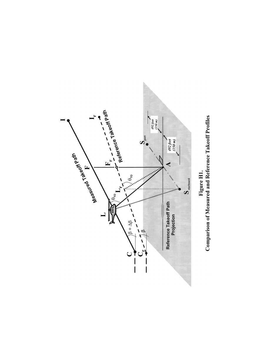
826
14 CFR Ch. I (1–1–24 Edition)
Pt. 36, App. H
(3) Figure H1 illustrates the significant ge-
ometrical relationships influencing sound
propagation. Position L represents the heli-
copter location on the measured takeoff path
from which PNLTM is observed at station A,
and L
r
is the corresponding position on the
reference sound propagation path. Propaga-
tion paths AL and AL
r
both form the same
VerDate Sep<11>2014
09:06 Jun 28, 2024
Jkt 262046
PO 00000
Frm 00836
Fmt 8010
Sfmt 8002
Y:\SGML\262046.XXX
262046
ER02JN04.000</GPH>
jspears on DSK121TN23PROD with CFR

827
Federal Aviation Administration, DOT
Pt. 36, App. H
angle
q
(theta) relative to their respective
flight paths.
(c)
Level flyover profiles. (1) The noise type
certification level flyover profile is shown in
Figure H2. Airspeed must be stabilized with-
in
±
5 knots of the reference airspeed deter-
mined using the procedures in section
H36.3(d). The number of level flights made
with a headwind component must be equal to
the number of level flights made with a tail-
wind component.
VerDate Sep<11>2014
09:06 Jun 28, 2024
Jkt 262046
PO 00000
Frm 00837
Fmt 8010
Sfmt 8002
Y:\SGML\262046.XXX
262046
jspears on DSK121TN23PROD with CFR
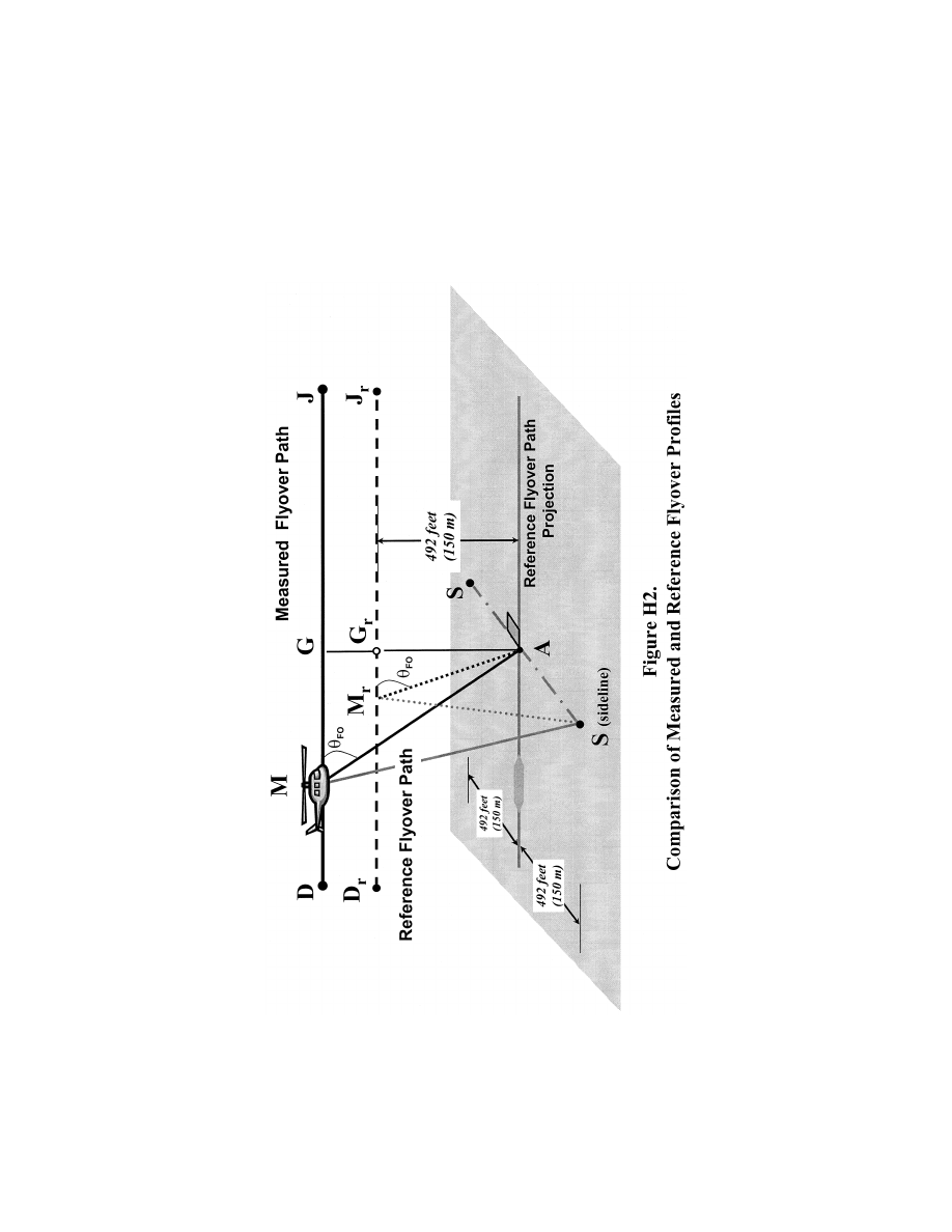
828
14 CFR Ch. I (1–1–24 Edition)
Pt. 36, App. H
(2) Figure H2 illustrates comparative fly-
over profiles when test conditions do not
conform to prescribed reference conditions.
The position of the helicopter shall be re-
corded for a distance (DJ) sufficient to en-
sure recording of the entire interval during
which the measured helicopter noise level is
VerDate Sep<11>2014
09:06 Jun 28, 2024
Jkt 262046
PO 00000
Frm 00838
Fmt 8010
Sfmt 8002
Y:\SGML\262046.XXX
262046
ER02JN04.001</GPH>
jspears on DSK121TN23PROD with CFR

829
Federal Aviation Administration, DOT
Pt. 36, App. H
within 10 dB of PNLTM, as required. The fly-
over profile is defined by the height AG
which is a function of the operating condi-
tions controlled by the pilot. Position M rep-
resents the helicopter location on the meas-
ured flyover flight path for which PNLTM is
observed at station A, and M
r
is the cor-
responding position on the reference flight
path.
(d)
Approach profiles. (1) Figure H3 illus-
trates a typical approach profile, including
reference conditions.
(2) The helicopter approaches position H
along a 6
°
(
±
0.5
°
) average approach slope
throughout the 10dB-down time interval. De-
viation from the 6
°
average approach slope
must be approved by the FAA before testing.
VerDate Sep<11>2014
09:06 Jun 28, 2024
Jkt 262046
PO 00000
Frm 00839
Fmt 8010
Sfmt 8002
Y:\SGML\262046.XXX
262046
jspears on DSK121TN23PROD with CFR
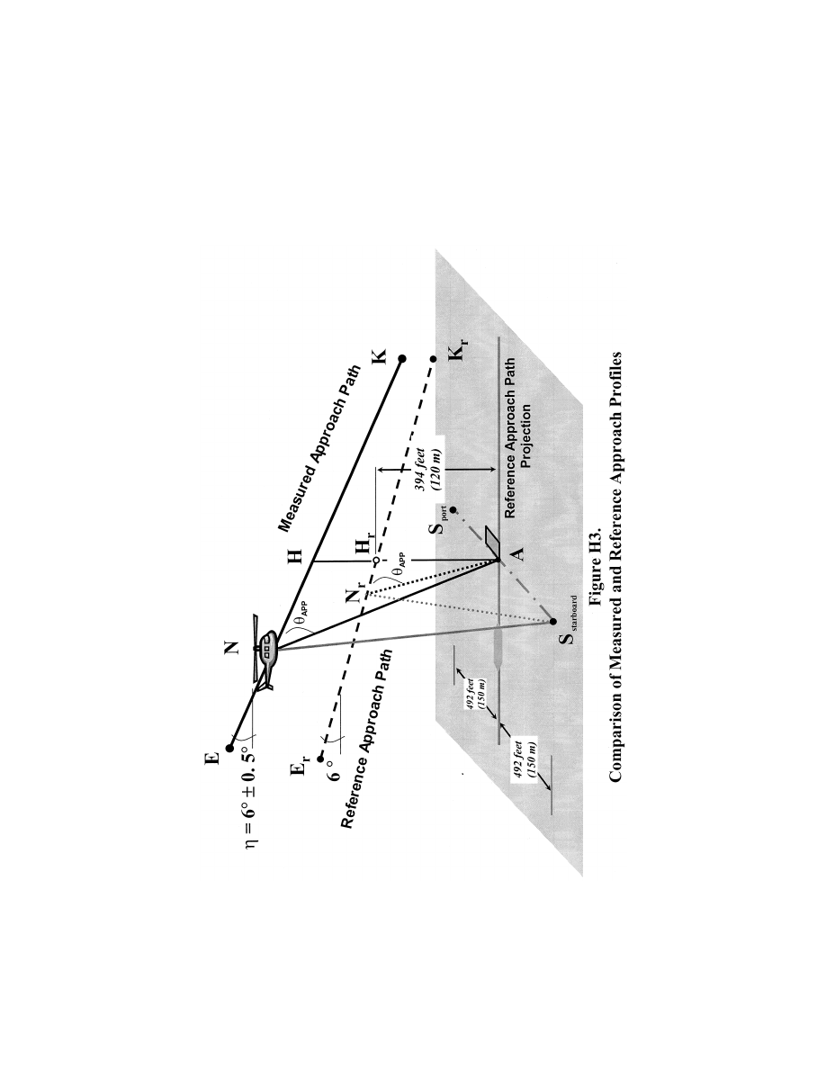
830
14 CFR Ch. I (1–1–24 Edition)
Pt. 36, App. H
(3) Figure H3 illustrates portions of the
measured and reference approach flight
paths including the significant geometrical
relationships influencing sound propagation.
The measured approach path is represented
by segment EK with an approach allowable
angle
q
. Reference positions, E
r
and K
r
, define
an idealized reference approach angle of 6
°
.
VerDate Sep<11>2014
09:06 Jun 28, 2024
Jkt 262046
PO 00000
Frm 00840
Fmt 8010
Sfmt 8002
Y:\SGML\262046.XXX
262046
ER02JN04.002</GPH>
jspears on DSK121TN23PROD with CFR

831
Federal Aviation Administration, DOT
Pt. 36, App. H
Position N represents the helicopter location
on the measured approach flight path for
which PNLTM is observed at measuring sta-
tion A, and N
r
is the corresponding position
on the reference approach flight path. The
measured and reference noise propagation
paths are AN and AN
r
, respectively, both of
which form the same angle,
q
APP
, cor-
responding to PNLTM relative to their ap-
proach flight paths.
(e)
Correction of noise at source during level
flyover. (1) For level overflight, if any com-
bination of the following three factors, air-
speed deviations from reference, rotor speed
deviations from reference, and temperature
deviations from reference, results in a noise
correlating parameter whose value deviates
from the reference value of this parameter,
then source noise adjustments must be de-
termined from the manufacturer’s data that
is approved by the FAA.
(2) Off-reference tip Mach number adjust-
ments must be based upon a sensitivity
curve of PNLTM versus advancing blade tip
Mach number, deduced from overflights per-
formed at different airspeeds surrounding
the reference airspeed. If the test aircraft is
unable to attain the reference value, then an
extrapolation of the sensitivity curve is per-
mitted if data cover at least a range of 0.03
Mach units. The advancing blade tip Mach
number must be computed using true air-
speed, onboard outside air temperature, and
rotor speed. A separate PNLTM versus ad-
vancing blade tip Mach number function
must be derived for each of the three certifi-
cation microphone locations,
i.e., centerline,
sideline left, and sideline right. Sideline left
and right are defined relative to the direc-
tion of flight for each run. PNLTM adjust-
ments are to be applied to each microphone
datum using the appropriate PNLTM func-
tion.
(f)
PNLT corrections. If the measured ambi-
ent atmospheric conditions of temperature
and relative humidity differ from those pre-
scribed as reference conditions under this ap-
pendix (77 degrees F and 70 percent, respec-
tively), corrections to the EPNL values must
be calculated from the measured data under
paragraph (a) of this section as follows:
(1)
Takeoff flight path. For the takeoff
flight path shown in Figure H1, the spectrum
of PNLTM observed at station A for the air-
craft at position L is decomposed into its in-
dividual SPL(
i) values.
(i) Step 1. A set of corrected values are
then computed as follows:
SPL(
i)
r
= SPL(
i) + C[
a
(
i)
¥
a
(
i)
o
]AL +
C
a
(
i)
o
(AL
¥
AL
r
) + 20 log (AL/AL
r
)
where SPL(
i) and SPL(i)
r
are the measured
and corrected sound pressure levels, respec-
tively, in the
i-th one-third octave band. The
first correction term adjusts for the effect of
change in atmospheric sound absorption
where
a
(
i) and
a
(
i)
o
are the sound attenuation
coefficients for the test and reference atmos-
pheric conditions, respectively, for the
i-th
one-third octave band, and AL is the meas-
ured takeoff sound propagation path. The
conversion factor constant,
C, is 0.001 for
English System of Units and is 0.01 for Inter-
national System of Units. The second correc-
tion term adjusts for the effects of atmos-
pheric attenuation due to the difference in
the sound propagation path length where AL
r
is the Reference takeoff sound propagation
path. The third correction term, known as
the ‘‘inverse square’’ law, adjusts for the ef-
fect of the difference in the sound propaga-
tion path lengths.
(ii) Step 2. The corrected values of the
SPL(
i)
r
are then converted to reference con-
dition PNLT and a correction term cal-
culated as follows:
D
1
= PNLT
¥
PNLTM
which represents the correction to be added
algebraically to the EPNL calculated from
the measured data.
(2)
Level flyover flight path. (i) The proce-
dure described in paragraph (f)(1) of this sec-
tion for takeoff paths is also used for the
level flyover paths, with the values of SPL(
i)
r
relating to the flyover sound propagation
paths shown in Figure H2 as follows:
SPL(
i)
r
= SPL(
i) + C[
a
(
i)
¥
a
(
i)
o
]AM +
C
a
(
i)
o
(AM
¥
AM
r
) + 20 log (AM/AM
r
)
where the lines AM and AM
r
are the meas-
ured and reference level flyover sound propa-
gation paths, respectively.
(ii) The remainder of the procedure is the
same for the flyover condition as that pre-
scribed in the paragraph (f)(1)(ii) of this sec-
tion regarding takeoff flight path.
(3)
Approach flight path. (i) The procedure
described in paragraph (f)(1) of this section
for takeoff paths is also used for the ap-
proach paths, with the values of SPL(
i)
r
re-
lating to the approach sound propagation
paths shown in Figure H3 as follows:
SPL(
i)
r
= SPL(
i) + C[
a
(
i)
¥
a
(
i)
o
]AN +
C
a
(
i)
o
(AN
¥
AN
r
) + 20 log (AN/AN
r
)
where the lines AN and AN
r
are the measured
and reference approach sound propagation
paths, respectively.
(ii) The remainder of the procedure is the
same for the approach condition as that pre-
scribed in the paragraph (f)(1)(ii) of this sec-
tion regarding takeoff flight path.
(4)
Sideline microphones. (i) The procedure
prescribed in paragraph (f)(1) of this section
for takeoff paths is also used for the propa-
gation to the sideline locations, with the val-
ues of SPL(
i)
r
relating as follows to the
measured sideline sound propagation path
shown in Figure H3 as follows:
SPL(
i)
r
= SPL(
i) + C[
a
(
i)
¥
a
(
i)
o
]SX +
C
a
(
i)
o
(SX
¥
SX
r
) + 20 log (SX/SX
r
)
where S is the sideline measuring station
and, based upon the flight condition, the hel-
icopter positions, X and X
r
, correspond to:
VerDate Sep<11>2014
09:06 Jun 28, 2024
Jkt 262046
PO 00000
Frm 00841
Fmt 8010
Sfmt 8003
Y:\SGML\262046.XXX
262046
jspears on DSK121TN23PROD with CFR

832
14 CFR Ch. I (1–1–24 Edition)
Pt. 36, App. H
X = L, and X
r
= L
r
for takeoff
X = M, and X
r
= M
r
for flyover
X = N, and X
r
= N
r
for approach
(ii) The remainder of the procedure is the
same for the sideline paths as that pre-
scribed in the paragraph (f)(1)(ii) of this sec-
tion regarding takeoff flight paths.
(g)
Duration corrections. (1) If the measured
takeoff and approach flight paths do not con-
form to those prescribed as the corrected and
reference flight paths, respectively, under
section A36.5(d)(2) it will be necessary to
apply duration corrections to the EPNL val-
ues calculated from the measured data. Such
corrections must be calculated as follows:
(i)
Takeoff flight path. For the takeoff path
shown in Figure H1, the correction term is
calculated using the formula—
D
2
=
¥
7.5 log (AL/AL
r
) + 10 log (V/V
r
)
which represents the correction that must be
added algebraically to the EPNL calculated
from the measured data. The lengths AL and
AL
r
are the measured and reference takeoff
distances from the noise measuring station
A to the measured and the reference takeoff
paths, respectively. A negative sign indicates
that, for the particular case of a duration
correction, the EPNL calculated from the
measured data must be reduced if the meas-
ured takeoff path is at greater altitude than
the reference takeoff path.
(ii)
Level flyover flight paths. For the level
flyover flight path, the correction term is
calculated using the formula—
D
2
=
¥
7.5 log (AM/AM
r
) + 10 log (V/V
r
)
where AM is the measured flyover distance
from the noise measuring station A to the
measured flyover path, and AM
r
is the ref-
erence distance from station A to the ref-
erence flyover path.
(iii)
Approach flight path. For the approach
path shown in Figure H3, the correction
term is calculated using the formula—
D
2
=
¥
7.5 log (AN/AN
r
) + 10 log (V/V
r
)
where AN is the measured approach distance
from the noise measuring station A to the
measured approach path, and AN
r
is the ref-
erence distance from station A to the ref-
erence approach path.
(iv)
Sideline microphones. For the sideline
flight path, the correction term is calculated
using the formula—
D
2
=
¥
7.5 log (SX/SX
r
) + 10 log (V/V
r
)
where S is the sideline measuring station
and based upon the flight condition, the heli-
copter positions, X and X
r
, correspond to:
X = L, and X
r
= L
r
for takeoff
X = M, and X
r
= M
r
for flyover
X = N, and X
r
= N
r
for approach
(2) The adjustment procedure described in
this section shall apply to the sideline
microphones in the take-off, overflight, and
approach cases. Although the noise emission
is strongly dependent on the directivity pat-
tern, variable from one helicopter type to
another, the propagation angle
q
shall be the
same for test and reference flight paths. The
elevation angle
y
shall not be constrained
but must be determined and reported. The
certification authority shall specify the ac-
ceptable limitations on
y
. Corrections to
data obtained when these limits are exceeded
shall be applied using FAA approved proce-
dures.
PART D
—
NOISE LIMITS UNDER
§ 36.805
Section H36.301 Noise measurement, evaluation,
and calculation.
Compliance with this part of this appendix
must be shown with noise levels measured,
evaluated, and calculated as prescribed
under Parts B and C of this appendix.
Section H36.303 [Reserved]
Section H36.305 Noise levels.
(a)
Limits. For compliance with this appen-
dix, the applicant must show by flight test
that the calculated noise levels of the heli-
copter, at the measuring points described in
section H36.305(a) of this appendix, do not ex-
ceed the following, (with appropriate inter-
polation between weights):
(1)
Stage 1 noise limits for acoustical
changes for helicopters are as follows:
(i) For takeoff, flyover, and approach cal-
culated noise levels, the noise levels of each
Stage 1 helicopter that exceed the Stage 2
noise limits plus 2 EPNdB may not, after a
change in type design, exceed the noise lev-
els created prior to the change in type de-
sign.
(ii) For takeoff, flyover, and approach cal-
culated noise levels, the noise levels of each
Stage 1 helicopter that do not exceed the
Stage 2 noise limits plus 2 EPNdB may not,
after the change in type design, exceed the
Stage 2 noise limits plus 2 EPNdB.
(2)
Stage 2 noise limits are as follows:
(i)
For takeoff calculated noise levels—109
EPNdB for maximum takeoff weights of
176,370 pounds (80,000 kg) or more, reduced by
3.01 EPNdB per halving of the weight down
to 89 EPNdB, after which the limit is con-
stant.
(ii)
For flyover calculated noise levels—108
EPNdB for maximum weights of 176,370
pounds (80,000 kg) or more, reduced by 3.01
EPNdB per halving of the weight down to 88
EPNdB, after which the limit is constant.
(iii)
For approach calculated noise levels—110
EPNdB for maximum weights of 176,370
pounds (80,000 kg) or more, reduced by 3.01
EPNdB per halving of the weight down to 90
EPNdB, after which the limit is constant.
(3)
Stage 3 noise limits are as follows:
(i) For takeoff—For a helicopter having a
maximum certificated takeoff weight of
176,370 pounds (80,000 kg) or more, the noise
limit is 106 EPNdB, which decreases linearly
VerDate Sep<11>2014
09:06 Jun 28, 2024
Jkt 262046
PO 00000
Frm 00842
Fmt 8010
Sfmt 8002
Y:\SGML\262046.XXX
262046
jspears on DSK121TN23PROD with CFR

833
Federal Aviation Administration, DOT
Pt. 36, App. J
with the logarithm of the helicopter weight
(mass) at a rate of 3.0 EPNdB per halving of
the weight (mass) down to 86 EPNdB, after
which the limit is constant.
(ii) For flyover—For a helicopter having a
maximum certificated takeoff weight of
176,370 pounds (80,000 kg) or more, the noise
limit is 104 EPNdB, which decreases linearly
with the logarithm of the helicopter weight
(mass) at a rate of 3.0 EPNdB per halving of
the weight (mass) down to 84 EPNdB, after
which the limit is constant.
(iii) For approach—For a helicopter having
a maximum certificated takeoff weight of
176,370 pounds (80,000 kg) or more, the noise
limit is 109 EPNdB, which decreases linearly
with the logarithm of the helicopter weight
(mass) at a rate of 3.0 EPNdB per halving of
the weight (mass) down to 89 EPNdB, after
which the limit is constant.
(b)
Tradeoffs. Except to the extent limited
under § 36.11(b) of this part, the noise limits
prescribed in paragraph (a) of this section
may be exceeded by one or two of the take-
off, flyover, or approach calculated noise lev-
els determined under section H36.203 of this
appendix if
(1) The sum of the exceedances is not
greater than 4 EPNdB;
(2) No exceedance is greater than 3 EPNdB;
and
(3) The exceedances are completely offset
by reduction in the other required calculated
noise levels.
[Amdt. 36–14, 53 FR 3541, Feb. 5, 1988; 53 FR
4099, Feb. 11, 1988; 53 FR 7728, Mar. 10, 1988, as
amended by Amdt. 36–54, 67 FR 45237, July 8,
2002; Amdt. 36–25, 69 FR 31234, June 2, 2004;
Amdt. 36–25, 69 FR 41573, July 9, 2004; Amdt.
36–30, 79 FR 12045, Mar. 4, 2014; FAA Doc. No.
FAA–2015–3782, Amdt. No. 36–31, 82 FR 46131,
Oct. 4, 2017]
A
PPENDIX
I
TO
P
ART
36 [R
ESERVED
]
A
PPENDIX
J
TO
P
ART
36—A
LTERNATIVE
N
OISE
C
ERTIFICATION
P
ROCEDURE
FOR
H
ELICOPTERS
U
NDER
S
UBPART
H
H
AVING
A
M
AXIMUM
C
ERTIFICATED
T
AKEOFF
W
EIGHT
OF
N
OT
M
ORE
T
HAN
7,000 P
OUNDS
PART A
—
REFERENCE CONDITIONS
Sec.
J36.1
General.
J36.3
Reference Test Conditions.
J36.5 [Reserved]
PART B
—
NOISE MEASUREMENT PROCEDURE
UNDER
§ 36.801
J36.101
Noise certification test and measurement
conditions.
J36.103 [Reserved]
J36.105
Flyover test conditions.
J36.107 [Reserved]
J36.109
Measurement of helicopter noise received
on the ground.
J36.111
Reporting requirements.
J36.113 [Reserved]
PART C
—
NOISE EVALUATION AND CALCULATION
UNDER
§ 36.803
J36.201
Noise evaluation in SEL.
J36.203
Calculation of noise levels.
J36.205
Detailed data correction procedures.
PART D
—
NOISE LIMITS PROCEDURE UNDER
§ 36.805
J36.301
Noise measurement, evaluation, and cal-
culation.
J36.303 [Reserved]
J36.305
Noise limits.
PART A
—
REFERENCE CONDITIONS
Section J36.1 General.
This appendix prescribes the alternative
noise certification requirements identified
under § 36.1 of this part and subpart H of this
part for helicopters in the primary, normal,
transport, and restricted categories having
maximum certificated takeoff weight of not
more than 7,000 pounds including:
(a) The conditions under which an alter-
native noise certification test under subpart
H of this part must be conducted and the al-
ternative measurement procedure that must
be used under § 36.801 of this part to measure
the helicopter noise during the test;
(b) The alternative procedures which must
be used under § 36.803 of this part to correct
the measured data to the reference condi-
tions and to calculate the noise evaluation
quantity designated as Sound Exposure
Level (SEL); and
(c) The noise limits for which compliance
must be shown under § 36.805 of this part.
Section J36.3 Reference Test Conditions.
(a)
Meteorological conditions. The following
are the noise certification reference atmos-
pheric conditions which shall be assumed to
exist from the surface to the helicopter alti-
tude:
(1) Sea level pressure of 2116 pounds per
square foot (76 centimeters mercury);
(2) Ambient temperature of 77 degrees
Fahrenheit (25 degrees Celsius);
(3) Relative humidity of 70 percent; and
(4) Zero wind.
(b)
Reference test site. The reference test
site is flat and without line-of-sight obstruc-
tions across the flight path that encom-
passes the 10 dB down points of the A-weight-
ed time history.
(c)
Level flyover reference profile. The ref-
erence flyover profile is a level flight, 492
feet (150 meters) above ground level as meas-
ured at the noise measuring station. The ref-
erence flyover profile has a linear flight
track and passes directly over the noise
VerDate Sep<11>2014
09:06 Jun 28, 2024
Jkt 262046
PO 00000
Frm 00843
Fmt 8010
Sfmt 8002
Y:\SGML\262046.XXX
262046
jspears on DSK121TN23PROD with CFR

834
14 CFR Ch. I (1–1–24 Edition)
Pt. 36, App. J
monitoring station. Airspeed is stabilized at
0.9V
H
; 0.9V
NE
; 0.45V
H
+ 65 kts (120 km/h); or
0.45V
NE
+ 65 kts (120 km/h), whichever of the
four airspeeds is least, and maintained
throughout the measured portion of the fly-
over. Rotor speed is stabilized at the max-
imum normal operating RPM throughout the
10 dB-down time interval.
(1) For noise certification purposes, V
H
is
defined as the airspeed in level flight ob-
tained using the minimum specification en-
gine power corresponding to maximum con-
tinuous power available for sea level pres-
sure of 2,116 psf (1,013.25 hPa) at 77
°
F (25
°
C)
ambient conditions at the relevant max-
imum certificated weight. The value of V
H
and V
NE
used for noise certification must be
included in the Flight Manual.
(2) V
NE
is the never-exceed airspeed.
(d) The weight of the helicopter shall be
the maximum takeoff weight at which noise
certification is requested.
Section J36.5 [Reserved]
P
ART
B—N
OISE
M
EASUREMENT
P
ROCEDURE
U
NDER
§ 36.801
Section J36.101 Noise certification test and
measurement conditions.
(a)
General. This section prescribes the con-
ditions under which helicopter noise certifi-
cation tests must be conducted and the
measurement procedures that must be used
to measure helicopter noise during each test.
(b)
Test site requirements. (1) The noise
measuring station must be surrounded by
terrain having no excessive sound absorption
characteristics, such as might be caused by
thick, matted, or tall grass, shrubs, or wood-
ed areas.
(2) During the period when the flyover
noise measurement is within 10 dB of the
maximum A-weighted sound level, no ob-
struction that significantly influences the
sound field from the helicopter may exist
within a conical space above the noise meas-
uring position (the point on the ground
vertically below the microphone), the cone is
defined by an axis normal to the ground and
by half-angle 80 degrees from this axis.
(c)
Weather restrictions. The test must be
conducted under the following atmospheric
conditions:
(1) No rain or other precipitation;
(2) Ambient air temperature between 36 de-
grees and 95 degrees Fahrenheit (2 degrees
and 35 degrees Celsius), inclusively, and rel-
ative humidity between 20 percent and 95
percent inclusively, except that testing may
not take place where combinations of tem-
perature and relative humidity result in a
rate of atmospheric attenuation greater than
10 dB per 100 meters (30.5 dB per 1000 ft) in
the one-third octave band centered at 8 kilo-
Hertz.
(3) Wind velocity that does not exceed 10
knots (19 km/h) and a crosswind component
that does not exceed 5 knots (9 km/h). The
wind shall be determined using a continuous
averaging process of no greater than 30 sec-
onds;
(4) Measurements of ambient temperature,
relative humidity, wind speed, and wind di-
rection must be made between 4 feet (1.2 me-
ters) and 33 feet (10 meters) above the
ground. Unless otherwise approved by the
FAA, ambient temperature and relative hu-
midity must be measured at the same height
above the ground.
(5) No anomalous wind conditions (includ-
ing turbulence) or other anomalous meteoro-
logical conditions that will significantly af-
fect the noise level of the helicopter when
the noise is recorded at the noise measuring
station; and
(6) If the measurement site is within 6560
feet (2,000 meters) of a fixed meteorological
station (such as those found at airports or
other facilities) the weather measurements
reported for temperature, relative humidity
and wind velocity may be used, if approved
by the FAA.
(d)
Helicopter testing procedures. (1) The hel-
icopter testing procedures and noise meas-
urements must be conducted and processed
in a manner which yields the noise evalua-
tion measure designated Sound Exposure
Level (SEL) as defined in section J36.109(b)
of this appendix.
(2) The helicopter height relative to the
noise measurement point sufficient to make
corrections required under section J36.205 of
this appendix must be determined by an
FAA-approved method that is independent of
normal flight instrumentation, such as radar
tracking, theodolite triangulation, laser
trajectography, or photographic scaling
techniques.
(3) If an applicant demonstrates that the
design characteristics of the helicopter
would prevent flight from being conducted in
accordance with the reference test condi-
tions prescribed under section J36.3 of this
appendix, then with FAA approval, the ref-
erence test conditions used under this appen-
dix may vary from the standard reference
test conditions, but only to the extent de-
manded by those design characteristics
which make compliance with the reference
test conditions impossible.
Section J36.103 [Reserved]
Section J36.105 Flyover test conditions.
(a) This section prescribes the flight test
conditions and allowable random deviations
for flyover noise tests conducted under this
appendix.
(b) A test series must consist of at least six
flights. The number of level flights made
with a headwind component must be equal to
VerDate Sep<11>2014
09:06 Jun 28, 2024
Jkt 262046
PO 00000
Frm 00844
Fmt 8010
Sfmt 8002
Y:\SGML\262046.XXX
262046
jspears on DSK121TN23PROD with CFR

835
Federal Aviation Administration, DOT
Pt. 36, App. J
the number of level flights made with a tail-
wind component over the noise measurement
station:
(1) In level flight and in cruise configura-
tion;
(2) At a height of 492 feet
±
50 feet (150
±
15
meters) above the ground level at the noise
measuring station; and
(3) Within
±
10 degrees from the zenith.
(c) Each flyover noise test must be con-
ducted:
(1) At the reference airspeed specified in
section J36.3(c) of this appendix, with such
airspeed adjusted as necessary to produce
the same advancing blade tip Mach number
as associated with the reference conditions;
(i) Advancing blade tip Mach number (M
AT
)
is defined as the ratio of the arithmetic sum
of blade tip rotational speed (V
R
) and the
helicopter true air speed (V
T
) over the speed
of sound (c) at 77 degrees Fahrenheit (1135.6
ft/sec or 346.13 m/sec) such that M
AT
= (V
R
+
V
T
)/c; and
(ii) The airspeed shall not vary from the
adjusted reference airspeed by more than
±
3
knots (
±
5 km/hr) or an equivalent FAA-ap-
proved variation from the reference advanc-
ing blade tip Mach number. The adjusted ref-
erence airspeed shall be maintained through-
out the measured portion of the flyover.
(2) At rotor speed stabilized at the power
on maximum normal operating rotor RPM
(
±
1 percent); and
(3) With the power stabilized during the pe-
riod when the measured helicopter noise
level is within 10 dB of the maximum A-
weighted sound level (L
AMAX
).
(d) The helicopter test weight for each fly-
over test must be within plus 5 percent or
minus 10 percent of the maximum takeoff
weight for which certification under this
part is requested.
(e) The requirements of paragraph (b)(2) of
this section notwithstanding, flyovers at an
FAA-approved lower height may be used and
the results adjusted to the reference meas-
urement point by an FAA-approved method
if the ambient noise in the test area, meas-
ured in accordance with the requirements
prescribed in section J36.109 of this appendix,
is found to be within 15 dB(A) of the max-
imum A-weighted helicopter noise level
(L
AMAX
) measured at the noise measurement
station in accordance with section J36.109 of
this appendix.
Section J36.107 [Reserved]
Section J36.109 Measurement of helicopter noise
received on the ground.
(a)
General. (1) The helicopter noise meas-
ured under this appendix for noise certifi-
cation purposes must be obtained with FAA-
approved acoustical equipment and measure-
ment practices.
(2) Paragraph (b) of this section identifies
and prescribes the specifications for the
noise evaluation measurements required
under this appendix. Paragraphs (c) and (d)
of this section prescribe the required acous-
tical equipment specifications. Paragraphs
(e) and (f) of this section prescribe the cali-
bration and measurement procedures re-
quired under this appendix.
(b)
Noise unit definition. (1) The value of
sound exposure level (SEL, or as denoted by
symbol, L
AE
), is defined as the level, in deci-
bels, of the time integral of squared ‘A’-
weighted sound pressure (P
A
) over a given
time period or event, with reference to the
square of the standard reference sound pres-
sure (P
O
) of 20 micropascals and a reference
duration of one second.
(2) This unit is defined by the expression:
L
Log
T
P t
P
dt dB
AE
A
t
t
=
⎛
⎝⎜
⎞
⎠⎟
∫
10
1
10
0
0
2
1
2
( )
Where T
O
is the reference integration time of
one second and (t
2
-t
1
) is the integration
time interval.
(3) The integral equation of paragraph
(b)(2) of this section can also be expressed as:
L
Log
T
dt dB
AE
L
t
t
t
=
∫
10
1
10
10
0
0 1
1
2
.
( )
A
Where L
A
(t) is the time varying A-weighted
sound level.
(4) The integration time (t
2
-t
1
) in practice
shall not be less than the time interval dur-
ing which L
A
(t) first rises to within 10 dB(A)
of its maximum value (L
AMAX
) and last falls
below 10 dB(A) of its maximum value.
(5) The SEL may be approximated by the
following expression:
L
AE
= L
AMAX
+ <delta>A
where <delta>A is the duration allowance
given by:
<delta>A = 10 log
10
(T)
where T = (t
2
-t
1
)/2 and L
AMAX
is defined as the
maximum level, in decibels, of the A-
weighted sound pressure (slow response)
with reference to the square of the stand-
ard reference sound pressure (P
0
).
(c)
Measurement system. The acoustical
measurement system must consist of FAA-
approved equipment equivalent to the fol-
lowing:
(1) A microphone system with frequency
response that is compatible with the meas-
urement and analysis system accuracy pre-
scribed in paragraph (d) of this section;
(2) Tripods or similar microphone mount-
ings that minimize interference with the
sound energy being measured;
(3) Recording and reproducing equipment
with characteristics, frequency response, and
dynamic range that are compatible with the
VerDate Sep<11>2014
09:06 Jun 28, 2024
Jkt 262046
PO 00000
Frm 00845
Fmt 8010
Sfmt 8002
Y:\SGML\262046.XXX
262046
EC28SE91.118</MATH>
EC28SE91.119</MATH>
jspears on DSK121TN23PROD with CFR

836
14 CFR Ch. I (1–1–24 Edition)
Pt. 36, App. J
response and accuracy requirements of para-
graph (d) of this section; and
(4) The calibration and checking of meas-
urement systems must use the procedures
described in Section A36.3.9.
(d)
Sensing, recording, and reproducing
equipment. (1) The noise levels measured from
helicopter flyovers under this appendix may
be determined directly by an integrating
sound level meter, or the A-weighted sound
level time history may be written onto a
graphic level recorder set at ‘‘slow’’ response
from which the SEL value may be deter-
mined. With the approval of the FAA, the
noise signal may be tape recorded for subse-
quent analysis.
(i) The SEL values from each flyover test
may be directly determined from an inte-
grating sound level meter complying with
the standards of IEC 804 (Incorporated by ref-
erence, see § 36.6) for a Type 1 instrument set
at ‘‘slow’’ response.
(ii) The acoustic signal from the heli-
copter, along with the calibration signals
specified under paragraph (e) of this section
and the background noise signal required
under paragraph (f) of this section, may be
recorded on a magnetic tape recorder for
subsequent analysis for an integrating sound
level meter identified in paragraph (d)(1)(i)
of this section. The record/playback system
(including the audio tape) of the tape re-
corder must conform to the requirements
prescribed in section A36.3.6 of appendix A to
this part. The tape recorder shall comply
with the specifications of IEC 561 (Incor-
porated by reference, see § 36.6).
(iii) The characteristics of the complete
system shall comply with the recommenda-
tions given in IEC 651 (Incorporated by ref-
erence, see § 36.6) with regard to the speci-
fications concerning microphone, amplifier,
and indicating instrument characteristics.
(iv) The response of the complete system
to a sensibly plane progressive wave of con-
stant amplitude shall lie within the toler-
ance limits specified in Table IV and Table V
for Type 1 instruments in IEC 651 for
weighting curve ‘‘A’’ over the frequency
range of 45 Hz to 11500 Hz.
(2) [Reserved]
(v) A windscreen must be used with the
microphone during each measurement of the
helicopter flyover noise. Correction for any
insertion loss produced by the windscreen, as
a function of the frequency of the acoustic
calibration required under paragraph (e) of
this section, must be applied to the meas-
ured data and any correction applied must be
reported.
(e)
Calibrations. (1) If the helicopter acous-
tic signal is tape recorded for subsequent
analysis, the measuring system and compo-
nents of the recording system must be cali-
brated as prescribed under section A36.3.6 of
appendix A of this part.
(2) If the helicopter acoustic signal is di-
rectly measured by an integrating sound
level meter:
(i) The overall sensitivity of the measuring
system shall be checked before and after the
series of flyover tests and at intervals (not
exceeding one-hour duration) during the fly-
over tests using an acoustic calibrator using
sine wave noise generating a known sound
pressure level at a known frequency.
(ii) The performance of equipment in the
system will be considered satisfactory if,
during each day’s testing, the variation in
the calibration value does not exceed 0.5 dB.
The SEL data collected during the flyover
tests shall be adjusted to account for any
variation in the calibration value.
(iii) A performance calibration analysis of
each piece of calibration equipment, includ-
ing acoustic calibrators, reference micro-
phones, and voltage insertion devices, must
have been made during the six calendar
months proceeding the beginning of the heli-
copter flyover series. Each calibration shall
be traceable to the National Institute of
Standards and Technology.
(f)
Noise measurement procedures. (1) The
microphone shall be of the pressure-sensitive
capacitive type designed for nearly uniform
grazing incidence response. The microphone
shall be mounted with the center of the sens-
ing element 4 feet (1.2 meters) above the
local ground surface and shall be oriented for
grazing incidence such that the sensing ele-
ment, the diaphragm, is substantially in the
plane defined by the nominal flight path of
the helicopter and the noise measurement
station.
(2) If a tape recorder is used, the frequency
response of the electrical system must be de-
termined at a level within 10 dB of the full-
scale reading used during the test, utilizing
pink or pseudorandom noise.
(3) The ambient noise, including both
acoustical background and electrical noise of
the measurement systems shall be deter-
mined in the test area and the system gain
set at levels which will be used for helicopter
noise measurements. If helicopter sound lev-
els do not exceed the background sound lev-
els by at least 15 dB(A), flyovers at an FAA-
approved lower height may be used and the
results adjusted to the reference measure-
ment point by an FAA-approved method.
(4) If an integrating sound level meter is
used to measure the helicopter noise, the in-
strument operator shall monitor the contin-
uous A-weighted (slow response) noise levels
throughout each flyover to ensure that the
SEL integration process includes, at min-
imum, all of the noise signal between the
maximum A-weighted sound level (L
AMAX
)
and the 10 dB down points in the flyover
time history. The instrument operator shall
note the actual db(A) levels at the start and
stop of the SEL integration interval and doc-
ument these levels along with the value of
VerDate Sep<11>2014
09:06 Jun 28, 2024
Jkt 262046
PO 00000
Frm 00846
Fmt 8010
Sfmt 8002
Y:\SGML\262046.XXX
262046
jspears on DSK121TN23PROD with CFR

837
Federal Aviation Administration, DOT
Pt. 36, App. J
L
AMAX
and the integration interval (in sec-
onds) for inclusion in the noise data sub-
mitted as part of the reporting requirements
under section J36.111(b) of this appendix.
Section J36.111 Reporting Requirements.
(a)
General. Data representing physical
measurements, and corrections to measured
data, including corrections to measurements
for equipment response deviations, must be
recorded in permanent form and appended to
the record. Each correction is subject to
FAA approval.
(b)
Data reporting. After the completion of
the test the following data must be included
in the test report furnished to the FAA:
(1) Measured and corrected sound levels ob-
tained with equipment conforming to the
standards prescribed in section J36.109 of this
appendix;
(2) The type of equipment used for meas-
urement and analysis of all acoustic, aircraft
performance and flight path, and meteoro-
logical data;
(3) The atmospheric environmental data
required to demonstrate compliance with
this appendix, measured throughout the test
period;
(4) Conditions of local topography, ground
cover, or events which may interfere with
the sound recording;
(5) The following helicopter information:
(i) Type, model, and serial numbers, if any,
of helicopter, engine(s) and rotor(s);
(ii) Gross dimensions of helicopter, loca-
tion of engines, rotors, type of antitorque
system, number of blades for each rotor, and
reference operating conditions for each en-
gine and rotor;
(iii) Any modifications of non-standard
equipment likely to affect the noise charac-
teristics of the helicopter;
(iv) Maximum takeoff weight for which
certification under this appendix is re-
quested;
(v) Aircraft configuration, including land-
ing gear positions;
(vi) V
H
or V
NE
(whichever is less) and the
adjusted reference airspeed;
(vii) Aircraft gross weight for each test
run;
(viii) Indicated and true airspeed for each
test run;
(ix) Ground speed, if measured, for each
run;
(x) Helicopter engine performance as deter-
mined from aircraft instruments and manu-
facturer’s data; and
(xi) Aircraft flight path above ground
level, referenced to the elevation of the noise
measurement station, in feet, determined by
an FAA-approved method which is inde-
pendent of normal flight instrumentation,
such as radar tracking, theodolite triangula-
tion, laser trajectography, or photoscaling
techniques; and
(6) Helicopter position and performance
data required to make the adjustments pre-
scribed under section J36.205 of this appendix
and to demonstrate compliance with the per-
formance and position restrictions pre-
scribed under section J36.105 of this appendix
must be recorded at an FAA-approved sam-
pling rate.
Section J36.113 [Reserved]
P
ART
C—N
OISE
E
VALUATION AND
C
ALCULATIONS
U
NDER
§ 36.803
Section J36.201 Noise Evaluation in SEL.
The noise evaluation measure shall be the
sound exposure level (SEL) in units of dB(A)
as prescribed under section J36.109(b) of this
appendix. The SEL value for each flyover
may be directly determined by use of an in-
tegrating sound level meter. Specifications
for the integrating sound level meter and re-
quirements governing the use of such instru-
mentation are prescribed under section
J36.109 of this appendix.
Section J36.203 Calculation of Noise Levels.
(a) To demonstrate compliance with the
noise level limits specified under section
J36.305 of this appendix, the SEL noise levels
from each valid flyover, corrected as nec-
essary to reference conditions under section
J36.205 of this appendix, must be
arithmetically averaged to obtain a single
SEL dB(A) mean value for the flyover series.
No individual flyover run may be omitted
from the averaging process, unless otherwise
specified or approved by the FAA.
(b) The minimum sample size acceptable
for the helicopter flyover certification meas-
urements is six. The number of samples must
be large enough to establish statistically a 90
percent confidence limit that does not ex-
ceed
±
1.5 dB(A).
(c) All data used and calculations per-
formed under this section, including the cal-
culated 90 percent confidence limits, must be
documented and provided under the report-
ing requirements of section J36.111 of this
appendix.
Section J36.205 Detailed Data Correction
Procedures.
(a) When certification test conditions
measured under part B of this appendix differ
from the reference test conditions prescribed
under section J36.3 of this appendix, appro-
priate adjustments shall be made to the
measured noise data in accordance with the
methods set out in paragraphs (b) and (c) of
this section. At minimum, appropriate ad-
justments shall be made for off-reference al-
titude and for the difference between ref-
erence airspeed and adjusted reference air-
speed.
(b) The adjustment for off-reference alti-
tude may be approximated from:
VerDate Sep<11>2014
09:06 Jun 28, 2024
Jkt 262046
PO 00000
Frm 00847
Fmt 8010
Sfmt 8002
Y:\SGML\262046.XXX
262046
jspears on DSK121TN23PROD with CFR

838
14 CFR Ch. I (1–1–24 Edition)
Pt. 36, App. K
<delta>J
1
= 12.5 log
10
(H
T
/492) dB;
where <delta>J
1
is the quantity in decibels
that must be algebraically added to the
measured SEL noise level to correct for
an off-reference flight path, H
T
is the
height, in feet, of the test helicopter
when directly over the noise measure-
ment point, and the constant (12.5) ac-
counts for the effects on spherical
spreading and duration from the off-ref-
erence altitude.
(c) The adjustment for the difference be-
tween reference airspeed and adjusted ref-
erence airspeed is calculated from:
<delta>J
3
= 10 log
10
(V
RA
/V
R
) dB;
Where <delta>J
3
is the quantity in decibels
that must be algebraically added to the
measured SEL noise level to correct for
the influence of the adjustment of the
reference airspeed on the duration of the
measured flyover event as perceived at
the noise measurement station, V
R
is the
reference airspeed as prescribed under
section J36.3.(c) of this appendix, and V
RA
is the adjusted reference airspeed as pre-
scribed under section J36.105(c) of this
appendix.
(d) No correction for source noise during
the flyover other than the variation of
source noise accounted for by the adjust-
ment of the reference airspeed prescribed for
under section J36.105(c) of this appendix need
be applied.
(e) No correction for the difference be-
tween the reference ground speed and the ac-
tual ground speed need be applied.
(f) No correction for off-reference atmos-
pheric attenuation need be applied.
(g) The SEL adjustments must be less than
2.0 dB(A) for differences between test and ref-
erence flight procedures prescribed under
section J36.105 of this appendix unless a larg-
er adjustment value is approved by the FAA.
(h) All data used and calculations per-
formed under this section must be docu-
mented and provided under the reporting re-
quirements specified under section J36.111 of
this appendix.
P
ART
D—N
OISE
L
IMITS
P
ROCEDURE
U
NDER
§ 36.805
Section J36.301 Noise Measurement, Evaluation,
and Calculation.
Compliance with this part of this appendix
must be shown with noise levels measured,
evaluated, and calculated as prescribed
under parts B and C of this appendix.
Section J36.303 [Reserved]
Section J36.305 Noise Limits.
For compliance with this appendix, the
calculated noise levels of the helicopter, at
the measuring point described in section
J36.101 of this appendix, must be shown to
not exceed the following (with appropriate
interpolation between weights):
(a) For primary, normal, transport, and re-
stricted category helicopters having a max-
imum certificated takeoff weight of not
more than 7,000 pounds that are noise tested
under this appendix:
(1) Stage 2 noise limit is constant at 82
decibels SEL for helicopters up to 1,737
pounds (787 kg) maximum certificated take-
off weight (mass) and increases linearly with
the logarithm of the helicopter weight at a
rate of 3.0 decibels SEL per the doubling of
weight thereafter. The limit may be cal-
culated by the equation:
L
AE
(limit) = 82 + 3.0 [log
10
(MTOW/1737)/
log
10
(2)] dB,
where MTOW is the maximum takeoff
weight, in pounds, for which certification
under this appendix is requested.
(2) Stage 3 noise limit is constant at 82
decibels SEL for helicopters up to 3,125
pounds (1,417 kg) maximum certificated
takeoff weight (mass) and increases linearly
with the logarithm of the helicopter weight
at a rate of 3.0 decibels SEL per the doubling
of weight thereafter. The limit may be cal-
culated using the equation:
L
AE
(limit) = 82 + 3.0 [log10(MTOW/3125)/
log10(2)] dB,
where MTOW is the maximum takeoff
weight, in pounds.
(b) The procedures required in this amend-
ment shall be done in accordance with the
International Electrotechnical Commission
IEC Publication No. 804, entitled ‘‘Inte-
grating-averaging Sound Level Meters,’’
First Edition, dated 1985. This incorporation
by reference was approved by the Director of
the Federal Register in accordance with 5
U.S.C. 552(a) and 1 CFR part 51. Copies may
be obtained from the Bureau Central de la
Commission Electrotechnique Inter-
nationale, 1, rue de Varembe, Geneva, Swit-
zerland or the American National Standard
Institute, 1430 Broadway, New York City,
New York 10018, or at the National Archives
and Records Administration (NARA). For in-
formation on the availability of this mate-
rial at NARA, call 202–741–6030, or go to:
http://www.archives.gov/federal
_
register/
code
_
of
_
federal
_
regulations/ibr
_
locations.html.
[Doc. No. 26910, 57 FR 42855, Sept. 16, 1992, as
amended by Amdt. 36–20, 57 FR 46243, Oct. 7,
1992; 69 FR 18803, Apr. 9, 2004; Amdt. 36–25, 69
FR 31234, June 2, 2004; Amdt. 36–30, 79 FR
12045, Mar. 4, 2014; FAA Doc. No. FAA–2015–
3782, Amdt. No. 36–31, 82 FR 46131, Oct. 4,
2017]
A
PPENDIX
K
TO
P
ART
36—N
OISE
R
E
-
QUIREMENTS FOR
T
ILTROTORS
U
NDER
S
UBPART
K
K1
General
VerDate Sep<11>2014
09:06 Jun 28, 2024
Jkt 262046
PO 00000
Frm 00848
Fmt 8010
Sfmt 8002
Y:\SGML\262046.XXX
262046
jspears on DSK121TN23PROD with CFR
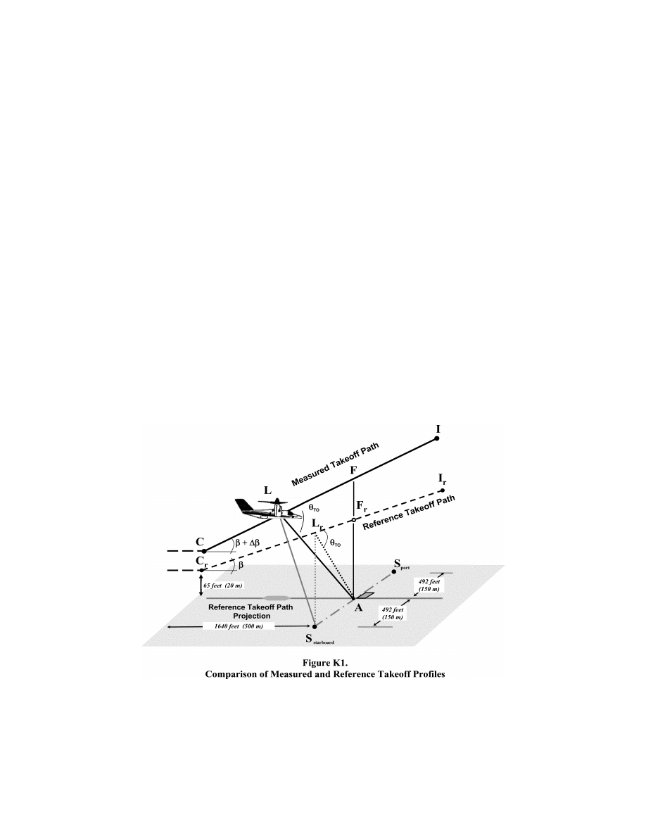
839
Federal Aviation Administration, DOT
Pt. 36, App. K
K2
Noise Evaluation Measure
K3
Noise Measurement Reference Points
K4
Noise Limits
K5
Trade-offs
K6
Noise Certification Reference Procedures
K7
Test Procedures
Section K1 General
This appendix prescribes noise limits and
procedures for measuring noise and adjusting
the data to standard conditions for tiltrotors
as specified in § 36.1 of this part.
Section K2 Noise Evaluation Measure
The noise evaluation measure is the effec-
tive perceived noise level in EPNdB, to be
calculated in accordance with section A36.4
of Appendix A to this part, except correc-
tions for spectral irregularities must be de-
termined using the 50 Hz sound pressure
level found in section H36.201 of Appendix H
to this part.
Section K3 Noise Measurement Reference Points
The following noise reference points must
be used when demonstrating tiltrotor com-
pliance with section K6 (Noise Certification
Reference Procedures) and section K7 (Test
Procedures) of this appendix:
(a)
Takeoff reference noise measurement
points—
As shown in Figure K1 below:
(1) The centerline noise measurement
flight path reference point, designated A, is
located on the ground vertically below the
reference takeoff flight path. The measure-
ment point is located 1,640 feet (500 m) in the
horizontal direction of flight from the point
Cr where transition to climbing flight is ini-
tiated, as described in section K6.2 of this ap-
pendix;
(2) Two sideline noise measurement points,
designated as S(starboard) and S(port), are
located on the ground perpendicular to and
symmetrically stationed at 492 feet (150 m)
on each side of the takeoff reference flight
path. The measurement points bisect the
centerline flight path reference point A.
(b)
Flyover reference noise measurement
points—
As shown in Figure K2 below:
(1) The centerline noise measurement
flight path reference point, designated A, is
located on the ground 492 feet (150 m)
vertically below the reference flyover flight
path. The measurement point is defined by
the flyover reference procedure in section
K6.3 of this appendix;
VerDate Sep<11>2014
09:06 Jun 28, 2024
Jkt 262046
PO 00000
Frm 00849
Fmt 8010
Sfmt 8002
Y:\SGML\262046.XXX
262046
ER08JA13.007</GPH>
jspears on DSK121TN23PROD with CFR
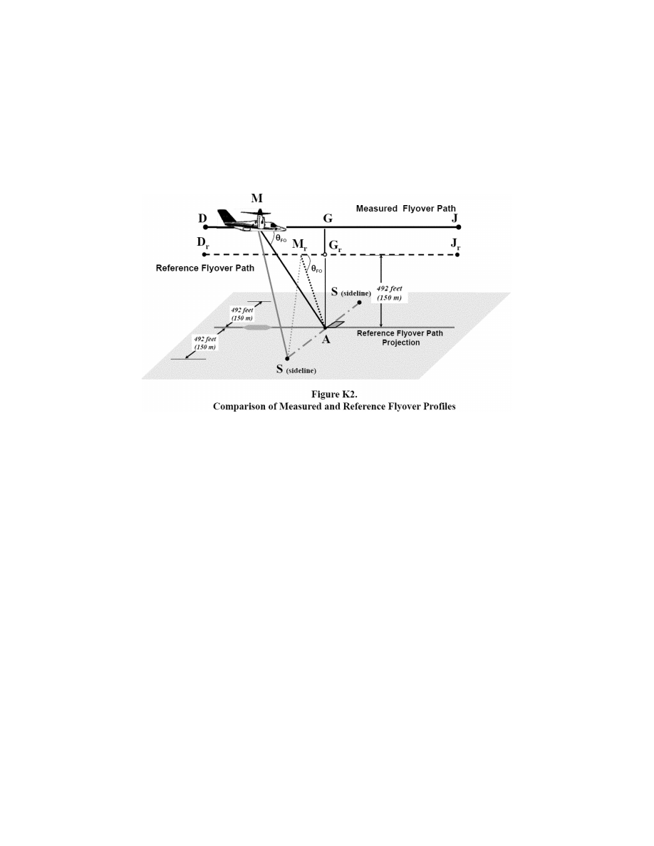
840
14 CFR Ch. I (1–1–24 Edition)
Pt. 36, App. K
(2) Two sideline noise measurement points,
designated as S
(
sideline
)
, are located on the
ground perpendicular to and symmetrically
stationed at 492 feet (150 m) on each side of
the flyover reference flight path. The meas-
urement points bisect the centerline flight
path reference point A.
(c)
Approach reference noise measurement
points—
As shown in Figure K3 below:
(1) The centerline noise measurement
flight path reference point, designated A, is
located on the ground 394 feet (120 m)
vertically below the reference approach
flight path. The measurement point is de-
fined by the approach reference procedure in
section K6.4 of this appendix. On level
ground, the measurement point corresponds
to a position 3,740 feet (1,140 m) from the
intersection of the 6.0 degree approach path
with the ground plane;
(2) Two sideline noise measurement points,
designated as S(starboard) and S(port), are
located on the ground perpendicular to and
symmetrically stationed at 492 feet (150 m)
on each side of the approach reference flight
path. The measurement points bisect the
centerline flight path reference point A.
VerDate Sep<11>2014
09:06 Jun 28, 2024
Jkt 262046
PO 00000
Frm 00850
Fmt 8010
Sfmt 8002
Y:\SGML\262046.XXX
262046
ER08JA13.008</GPH>
jspears on DSK121TN23PROD with CFR
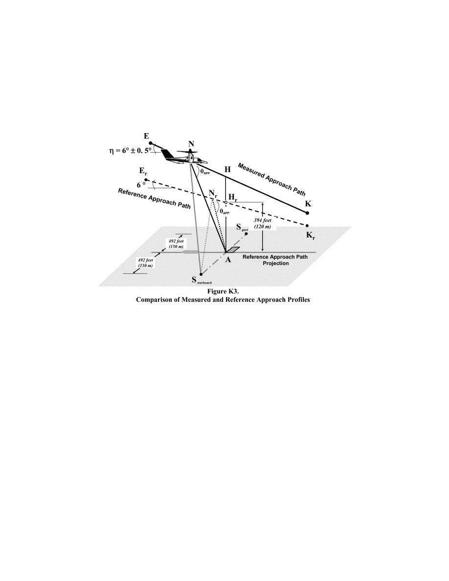
841
Federal Aviation Administration, DOT
Pt. 36, App. K
Section K4 Noise Limits
For a tiltrotor, the maximum noise levels,
as determined in accordance with the noise
evaluation in EPNdB and calculation method
described in section H36.201 of Appendix H of
this part, must not exceed the noise limits as
follows:
(a)
At the takeoff flight path reference point:
For a tiltrotor having a maximum certifi-
cated takeoff weight (mass) of 176,370 pounds
(80,000 kg) or more, in VTOL/Conversion
mode, 109 EPNdB, decreasing linearly with
the logarithm of the tiltrotor weight (mass)
at a rate of 3.0 EPNdB per halving of weight
(mass) down to 89 EPNdB, after which the
limit is constant. Figure K4 illustrates the
takeoff noise limit as a solid line.
(b)
At the Flyover path reference point: For a
tiltrotor having a maximum certificated
takeoff weight (mass) of 176,370 pounds
(80,000 kg) or more, in VTOL/Conversion
mode, 108 EPNdB, decreasing linearly with
the logarithm of the tiltrotor weight (mass)
at a rate of 3.0 EPNdB per halving of weight
(mass) down to 88 EPNdB, after which the
limit is constant. Figure K4 illustrates the
flyover noise limit as a dashed line.
(c)
At the approach flight path reference
point: For a tiltrotor having a maximum cer-
tificated takeoff weight (mass) of 176,370
pounds (80,000 kg) or more, in VTOL/Conver-
sion mode, 110 EPNdB, decreasing linearly
with the logarithm of the tiltrotors weight
(mass) at a rate of 3.0 EPNdB per halving of
weight (mass) down to 90 EPNdB, after which
the limit is constant. Figure K4 illustrates
the approach noise limit as a dash-dot line.
VerDate Sep<11>2014
09:06 Jun 28, 2024
Jkt 262046
PO 00000
Frm 00851
Fmt 8010
Sfmt 8002
Y:\SGML\262046.XXX
262046
ER08JA13.009</GPH>
jspears on DSK121TN23PROD with CFR
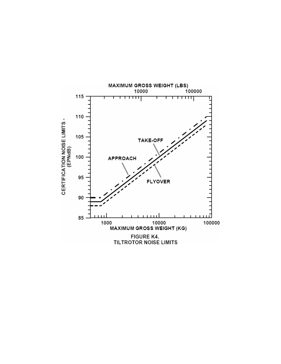
842
14 CFR Ch. I (1–1–24 Edition)
Pt. 36, App. K
Section K5 Trade-Offs
If the noise evaluation measurement ex-
ceeds the noise limits described in K4 of this
appendix at one or two measurement points:
(a) The sum of excesses must not be great-
er than 4 EPNdB;
(b) The excess at any single point must not
be greater than 3 EPNdB; and
(c) Any excess must be offset by the re-
maining noise margin at the other point or
points.
Section K6 Noise Certification Reference
Procedures
K6.1 General Conditions
(a)–(b) [Reserved]
(c) The takeoff, flyover and approach ref-
erence procedures must be established in ac-
cordance with sections K6.2, K6.3 and K6.4 of
this appendix, except as specified in section
K6.1(d) of this appendix.
(d) If the design characteristics of the
tiltrotor prevent test flights from being con-
ducted in accordance with section K6.2, K6.3
or K6.4 of this appendix, the applicant must
revise the test procedures and resubmit the
procedures for approval.
(e) The following reference atmospheric
conditions must be used to establish the ref-
erence procedures:
(1) Sea level atmospheric pressure of 2,116
pounds per square foot (1,013.25 hPa);
(2) Ambient air temperature of 77
°
Fahrenheit (25
°
Celsius, i.e. ISA + 10
°
C);
(3) Relative humidity of 70 percent; and
(4) Zero wind.
(f) For tests conducted in accordance with
sections K6.2, K6.3, and K6.4 of this appendix,
use the maximum normal operating RPM
VerDate Sep<11>2014
09:06 Jun 28, 2024
Jkt 262046
PO 00000
Frm 00852
Fmt 8010
Sfmt 8002
Y:\SGML\262046.XXX
262046
ER08JA13.010</GPH>
jspears on DSK121TN23PROD with CFR

843
Federal Aviation Administration, DOT
Pt. 36, App. K
corresponding to the airworthiness limit im-
posed by the manufacturer. For configura-
tions for which the rotor speed automati-
cally links with the flight condition, use the
maximum normal operating rotor speed cor-
responding with the reference flight condi-
tion. For configurations for which the rotor
speed can change by pilot action, use the
highest normal rotor speed specified in the
flight manual limitation section for the ref-
erence conditions.
K6.2 Takeoff Reference Procedure. The take-
off reference flight procedure is as follows:
(a) A constant takeoff configuration must
be maintained, including the nacelle angle
selected by the applicant;
(b) The tiltrotor power must be stabilized
at the maximum takeoff power cor-
responding to the minimum installed en-
gine(s) specification power available for the
reference ambient conditions or gearbox
torque limit, whichever is lower. The
tiltrotor power must also be stabilized along
a path starting from a point located 1,640
feet (500 m) before the flight path reference
point, at 65 ft (20 m) above ground level;
(c) The nacelle angle and the cor-
responding best rate of climb speed, or the
lowest approved speed for the climb after
takeoff, whichever is the greater, must be
maintained throughout the takeoff reference
procedure;
(d) The rotor speed must be stabilized at
the maximum normal operating RPM certifi-
cated for takeoff;
(e) The weight (mass) of the tiltrotors
must be the maximum takeoff weight (mass)
as requested for noise certification; and
(f) The reference takeoff flight profile is a
straight line segment inclined from the
starting point 1,640 feet (500 m) before to the
center noise measurement point and 65 ft (20
m) above ground level at an angle defined by
best rate of climb and the speed cor-
responding to the selected nacelle angle and
for minimum specification engine perform-
ance.
K6.3 Flyover Reference Procedure. The fly-
over reference flight procedure is as follows:
(a) The tiltrotor must be stabilized for
level flight along the centerline flyover
flight path and over the noise measurement
reference point at an altitude of 492 ft (150 m)
above ground level;
(b) A constant flyover configuration se-
lected by the applicant must be maintained;
(c) The weight (mass) of the tiltrotor must
be the maximum takeoff weight (mass) as re-
quested for noise certification;
(d) In the VTOL/Conversion mode:
(1) The nacelle angle must be at the au-
thorized fixed operation point that is closest
to the shallow nacelle angle certificated for
zero airspeed;
(2) The airspeed must be 0.9V
CON
and
(3) The rotor speed must be stabilized at
the maximum normal operating RPM certifi-
cated for level flight.
K6.4 Approach Reference Procedure. The ap-
proach reference procedure is as follows:
(a) The tiltrotor must be stabilized to fol-
low a 6.0 degree approach path;
(b) An approved airworthiness configura-
tion in which maximum noise occurs must be
maintained;
(1) An airspeed equal to the best rate of
climb speed corresponding to the nacelle
angle, or the lowest approved airspeed for
the approach, whichever is greater, must be
stabilized and maintained; and
(2) The tiltrotor power during the approach
must be stabilized over the flight path ref-
erence point, and continue as if landing;
(c) The rotor speed must be stabilized at
the maximum normal operating RPM certifi-
cated for approach;
(d) The constant approach configuration
used in airworthiness certification tests,
with the landing gear extended, must be
maintained; and
(e) The weight (mass) of the tiltrotor at
landing must be the maximum landing
weight (mass) as requested for noise certifi-
cation.
Section K7 Test Procedures
K7.1 [Reserved]
K7.2 The test procedures and noise meas-
urements must be conducted and processed
to yield the noise evaluation measure des-
ignated in section K2 of this appendix.
K7.3 If either the test conditions or test
procedures do not comply to the applicable
noise certification reference conditions or
procedures prescribed by this part, the appli-
cant must apply the correction methods de-
scribed in section H36.205 of Appendix H of
this part to the acoustic test data measured.
K7.4 Adjustments for differences between
test and reference flight procedures must not
exceed:
(a) For takeoff: 4.0 EPNdB, of which the
arithmetic sum of delta 1 and the term
¥
7.5
log (QK/QrKr) from delta 2 must not in total
exceed 2.0 EPNdB;
(b) For flyover or approach: 2.0 EPNdB.
K7.5 The average rotor RPM must not vary
from the normal maximum operating RPM
by more than
±
1.0 percent throughout the 10
dB-down time interval.
K7.6 The tiltrotor airspeed must not vary
from the reference airspeed appropriate to
the flight demonstration by more than
±
5 kts
(
±
9 km/h) throughout the 10 dB-down time
interval.
K7.7 The number of level flyovers made
with a head wind component must be equal
to the number of level flyovers made with a
tail wind component.
K7.8 The tiltrotor must operate between
±
10 degrees from the vertical or between
±
65
feet (
±
20 m) lateral deviation tolerance,
VerDate Sep<11>2014
09:06 Jun 28, 2024
Jkt 262046
PO 00000
Frm 00853
Fmt 8010
Sfmt 8002
Y:\SGML\262046.XXX
262046
jspears on DSK121TN23PROD with CFR

844
14 CFR Ch. I (1–1–24 Edition)
Pt. 39
whichever is greater, above the reference
track and throughout the 10 dB-down time
interval.
K7.9 The tiltrotor altitude must not vary
during each flyover by more than
±
30 ft (
±
9
m) from the reference altitude throughout
the 10 dB-down time interval.
K7.10 During the approach procedure, the
tiltrotor must establish a stabilized constant
speed approach and fly between approach an-
gles of 5.5 degrees and 6.5 degrees throughout
the 10 dB-down time interval.
K7.11 During all test procedures, the
tiltrotor weight (mass) must not be less than
90 percent and not more than 105 percent of
the maximum certificated weight (mass).
For each of the test procedures, complete at
least one test at or above this maximum cer-
tificated weight (mass).
K7.12 A tiltrotor capable of carrying exter-
nal loads or external equipment must be
noise certificated without such loads or
equipment fitted
K7.13 The value of V
CON
used for noise cer-
tification must be included in the approved
Flight Manual.
[78 FR 1139, Jan. 8, 2013]
PART 39—AIRWORTHINESS
DIRECTIVES
Sec.
39.1
Purpose of this regulation.
39.3
Definition of airworthiness directives.
39.5
When does FAA issue airworthiness di-
rectives?
39.7
What is the legal effect of failing to
comply with an airworthiness directive?
39.9
What if I operate an aircraft or use a
product that does not meet the require-
ments of an airworthiness directive?
39.11
What actions do airworthiness direc-
tives require?
39.13
Are airworthiness directives part of
the Code of Federal Regulations?
39.15
Does an airworthiness directive apply
if the product has been changed?
39.17
What must I do if a change in a prod-
uct affects my ability to accomplish the
actions required in an airworthiness di-
rective?
39.19
May I address the unsafe condition in
a way other than that set out in the air-
worthiness directive?
39.21
Where can I get information about
FAA-approved alternative methods of
compliance?
39.23
May I fly my aircraft to a repair facil-
ity to do the work required by an air-
worthiness directive?
39.25
How do I get a special flight permit?
39.27
What do I do if the airworthiness di-
rective conflicts with the service docu-
ment on which it is based?
A
UTHORITY
: 49 U.S.C. 106(g), 40113, 44701.
S
OURCE
: Docket No. FAA–2000–8460, 67 FR
48003, July 22, 2002, unless otherwise noted.
§ 39.1
Purpose of this regulation.
The regulations in this part provide a
legal framework for FAA’s system of
Airworthiness Directives.
§ 39.3
Definition of airworthiness di-
rectives.
FAA’s airworthiness directives are
legally enforceable rules that apply to
the following products: aircraft, air-
craft engines, propellers, and appli-
ances.
§ 39.5
When does FAA issue airworthi-
ness directives?
FAA issues an airworthiness direc-
tive addressing a product when we find
that:
(a) An unsafe condition exists in the
product; and
(b) The condition is likely to exist or
develop in other products of the same
type design.
§ 39.7
What is the legal effect of failing
to comply with an airworthiness di-
rective?
Anyone who operates a product that
does not meet the requirements of an
applicable airworthiness directive is in
violation of this section.
§ 39.9
What if I operate an aircraft or
use a product that does not meet
the requirements of an airworthi-
ness directive?
If the requirements of an airworthi-
ness directive have not been met, you
violate § 39.7 each time you operate the
aircraft or use the product.
§ 39.11
What actions do airworthiness
directives require?
Airworthiness directives specify in-
spections you must carry out, condi-
tions and limitations you must comply
with, and any actions you must take to
resolve an unsafe condition.
§ 39.13
Are airworthiness directives
part of the Code of Federal Regula-
tions?
Yes, airworthiness directives are part
of the Code of Federal Regulations, but
VerDate Sep<11>2014
09:06 Jun 28, 2024
Jkt 262046
PO 00000
Frm 00854
Fmt 8010
Sfmt 8010
Y:\SGML\262046.XXX
262046
jspears on DSK121TN23PROD with CFR