
5
SUBCHAPTER D—AIRMEN
PART 60—FLIGHT SIMULATION
TRAINING DEVICE INITIAL AND
CONTINUING QUALIFICATION
AND USE
Sec.
60.1
Applicability.
60.2
Applicability of sponsor rules to per-
sons who are not sponsors and who are
engaged in certain unauthorized activi-
ties.
60.3
Definitions.
60.4
Qualification Performance Standards.
60.5
Quality management system.
60.7
Sponsor qualification requirements.
60.9
Additional responsibilities of the spon-
sor.
60.11
FSTD use.
60.13
FSTD objective data requirements.
60.14
Special equipment and personnel re-
quirements for qualification of the
FSTD.
60.15
Initial qualification requirements.
60.16
Additional qualifications for a cur-
rently qualified FSTD.
60.17
Previously qualified FSTDs.
60.19
Inspection, continuing qualification
evaluation, and maintenance require-
ments.
60.20
Logging FSTD discrepancies.
60.21
Interim qualification of FSTDs for
new aircraft types or models.
60.23
Modifications to FSTDs.
60.25
Operation with missing, malfunc-
tioning, or inoperative components.
60.27
Automatic loss of qualification and
procedures for restoration of qualifica-
tion.
60.29
Other losses of qualification and pro-
cedures for restoration of qualification.
60.31
Recordkeeping and reporting.
60.33
Applications, logbooks, reports, and
records: Fraud, falsification, or incorrect
statements.
60.35
Specific full flight simulator compli-
ance requirements.
60.37
FSTD qualification on the basis of a
Bilateral Aviation Safety Agreement
(BASA).
A
PPENDIX
A
TO
P
ART
60—Q
UALIFICATION
P
ER
-
FORMANCE
S
TANDARDS
FOR
A
IRPLANE
F
ULL
F
LIGHT
S
IMULATORS
A
PPENDIX
B
TO
P
ART
60—Q
UALIFICATION
P
ER
-
FORMANCE
S
TANDARDS
FOR
A
IRPLANE
F
LIGHT
T
RAINING
D
EVICES
A
PPENDIX
C
TO
P
ART
60—Q
UALIFICATION
P
ER
-
FORMANCE
S
TANDARDS
FOR
H
ELICOPTER
F
ULL
F
LIGHT
S
IMULATORS
A
PPENDIX
D
TO
P
ART
60—Q
UALIFICATION
P
ER
-
FORMANCE
S
TANDARDS
FOR
H
ELICOPTER
F
LIGHT
T
RAINING
D
EVICES
A
PPENDIX
E
TO
P
ART
60—Q
UALIFICATION
P
ER
-
FORMANCE
S
TANDARDS FOR
Q
UALITY
M
AN
-
AGEMENT
S
YSTEMS FOR
F
LIGHT
S
IMULA
-
TION
T
RAINING
D
EVICES
A
PPENDIX
F
TO
P
ART
60—D
EFINITIONS AND
A
B
-
BREVIATIONS
FOR
F
LIGHT
S
IMULATION
T
RAINING
D
EVICES
A
UTHORITY
: 49 U.S.C. 106(f), 106(g), 40113,
and 44701; Pub. L. 111–216, 124 Stat. 2348 (49
U.S.C. 44701 note)
S
OURCE
: Docket No. FAA–2002–12461, 71 FR
63426, Oct. 30, 2006, unless otherwise noted.
§ 60.1
Applicability.
(a) This part prescribes the rules gov-
erning the initial and continuing quali-
fication and use of all aircraft flight
simulation training devices (FSTD)
used for meeting training, evaluation,
or flight experience requirements of
this chapter for flight crewmember cer-
tification or qualification.
(b) The rules of this part apply to
each person using or applying to use an
FSTD to meet any requirement of this
chapter.
(c) The requirements of § 60.33 regard-
ing falsification of applications,
records, or reports also apply to each
person who uses an FSTD for training,
evaluation, or obtaining flight experi-
ence required for flight crewmember
certification or qualification under
this chapter.
§ 60.2
Applicability of sponsor rules to
persons who are not sponsors and
who are engaged in certain unau-
thorized activities.
(a) The rules of this part that are di-
rected to a sponsor of an FSTD also
apply to any person who uses or causes
the use of an FSTD when—
(1) That person knows that the FSTD
does not have an FAA-approved spon-
sor; and
(2) The use of the FSTD by that per-
son is nonetheless claimed for purposes
of meeting any requirement of this
chapter or that person knows or should
have known that the person’s acts or
omissions would cause another person
to mistakenly credit use of the FSTD
for purposes of meeting any require-
ment of this chapter.
VerDate Sep<11>2014
14:00 Mar 14, 2024
Jkt 262047
PO 00000
Frm 00015
Fmt 8010
Sfmt 8010
Q:\14\14V2.TXT
PC31
aworley on LAPBH6H6L3 with DISTILLER

6
14 CFR Ch. I (1–1–24 Edition)
§ 60.3
(b) A situation in which paragraph
(a) of this section would not apply to a
person would be when each of the fol-
lowing conditions are met:
(1) The person sold or leased the
FSTD and merely represented to the
purchaser or lessee that the FSTD is in
a condition in which it should be able
to obtain FAA approval and qualifica-
tion under this part;
(2) The person does not falsely claim
to be the FAA-approved sponsor for the
FSTD;
(3) The person does not falsely make
representations that someone else is
the FAA-approved sponsor of the FSTD
at a time when that other person is not
the FAA-approved sponsor of the
FSTD; and
(4) The person’s acts or omissions do
not cause another person to detrimen-
tally rely on such acts or omissions for
the mistaken conclusion that the
FSTD is FAA-approved and qualified
under this part at the time the FSTD
is sold or leased.
§ 60.3
Definitions.
In addition to the definitions in part
1 of this chapter, other terms and defi-
nitions applicable to this part are
found in appendix F of this part.
§ 60.4
Qualification Performance
Standards.
The Qualification Performance
Standards (QPS) are published in ap-
pendices to this part as follows:
(a) Appendix A contains the QPS for
Airplane Flight Simulators.
(b) Appendix B contains the QPS for
Airplane Flight Training Devices.
(c) Appendix C contains the QPS for
Helicopter Flight Simulators.
(d) Appendix D contains the QPS for
Helicopter Flight Training Devices.
(e) Appendix E contains the QPS for
Quality Management Systems for
FSTDs.
(f) Appendix F contains the QPS for
Definitions and Abbreviations for
FSTDs.
§ 60.5
Quality management system.
(a) After May 30, 2010, no sponsor
may use or allow the use of or offer the
use of an FSTD for flight crewmember
training or evaluation or for obtaining
flight experience to meet any require-
ment of this chapter unless the sponsor
has established and follows a quality
management system (QMS), currently
approved by the responsible Flight
Standards office, for the continuing
surveillance and analysis of the spon-
sor’s performance and effectiveness in
providing a satisfactory FSTD for use
on a regular basis as described in QPS
appendix E of this part.
(b) The QMS program must provide a
process for identifying deficiencies in
the program and for documenting how
the program will be changed to address
these deficiencies.
(c) Whenever the responsible Flight
Standards office finds that the QMS
program does not adequately address
the procedures necessary to meet the
requirements of this part, the sponsor
must, after notification by the respon-
sible Flight Standards office, change
the program so the procedures meet
the requirements of this part. Each
such change must be approved by the
responsible Flight Standards office
prior to implementation.
(d) Within 30 days after the sponsor
receives a notice described in para-
graph (c) of this section, the sponsor
may file a petition with the Executive
Director of Flight Standards Service
(the Executive Director) for reconsider-
ation of the responsible Flight Stand-
ards office finding. The sponsor must
address its petition to the Executive
Director, Flight Standards Service,
Federal Aviation Administration, 800
Independence Ave., SW., Washington,
DC 20591. The filing of such a petition
to reconsider stays the notice pending
a decision by the Executive Director.
However, if the Executive Director
finds that there is a situation that re-
quires immediate action in the interest
of safety in air commerce, he may,
upon a statement of the reasons, re-
quire a change effective without stay.
[Doc. No. FAA–2002–12461, 71 FR 63426, Oct.
30, 2006; Amdt. 60–2, 72 FR 59599, Oct. 22, 2007,
as amended by Docket FAA–2018–0119, Amdt.
60–5, 83 FR 9170, Mar. 5, 2018; Docket No.
FAA–2022–1355; Amdt. No. 60–7, 87 FR 75711,
Dec. 9, 2022]
VerDate Sep<11>2014
14:00 Mar 14, 2024
Jkt 262047
PO 00000
Frm 00016
Fmt 8010
Sfmt 8010
Q:\14\14V2.TXT
PC31
aworley on LAPBH6H6L3 with DISTILLER

7
Federal Aviation Administration, DOT
§ 60.7
§ 60.7
Sponsor qualification require-
ments.
(a) A person is eligible to apply to be
a sponsor of an FSTD if the following
conditions are met:
(1) The person holds, or is an appli-
cant for, a certificate under part 119,
141, or 142 of this chapter; or holds, or
is an applicant for, an approved flight
engineer course in accordance with
part 63 of this chapter.
(2) The FSTD will be used, or will be
offered for use, in the sponsor’s FAA-
approved flight training program for
the aircraft being simulated as evi-
denced in a request for evaluation sub-
mitted to the responsible Flight Stand-
ards office.
(b) A person is a sponsor if the fol-
lowing conditions are met:
(1) The person is a certificate holder
under part 119, 141, or 142 of this chap-
ter or has an approved flight engineer
course in accordance with part 63 of
this chapter.
(2) The person has—
(i) Operations specifications author-
izing the use of the specific aircraft or
set of aircraft and has an FAA-ap-
proved training program under which
at least one FSTD, simulating the air-
craft or set of aircraft and for which
the person is the sponsor, is used by
the sponsor as described in paragraphs
(b)(5) or (b)(6) of this section; or
(ii) Training specifications or an
FAA-approved course of training under
which at least one FSTD, simulating
that aircraft or set of aircraft and for
which the person is the sponsor, is used
by the sponsor as described in para-
graphs (b)(5) or (b)(6) of this section.
(3) The person has a quality manage-
ment system currently approved by the
responsible Flight Standards office in
accordance with § 60.5.
(4) The responsible Flight Standards
office has accepted the person as the
sponsor of the FSTD and that accept-
ance has not been withdrawn by the
FAA.
(5) At least one FSTD (as referenced
in paragraph (b)(2)(i) or (b)(2)(ii) of this
section) that is initially qualified on or
after May 30, 2008, is used within the
sponsor’s FAA-approved flight training
program for the aircraft or set of air-
craft at least once within the 12-month
period following the initial/upgrade
evaluation, and at least once within
each subsequent 12-month period there-
after.
(6) At least one FSTD (as referenced
in paragraph (b)(2)(i) or (b)(2)(ii) of this
section) that was qualified before May
30, 2008, is used within the sponsor’s
FAA-approved flight training program
for the aircraft or set of aircraft at
least once within the 12-month period
following the first continuing quali-
fication evaluation conducted by the
responsible Flight Standards office
after May 30, 2008 and at least once
within each subsequent 12-month pe-
riod thereafter.
(c) If the use requirements of para-
graphs (b)(2) and either (b)(5) or (b)(6)
of this section are not met, the person
will forfeit the right to sponsor that
FSTD and that person will not be eligi-
ble to apply to sponsor that FSTD for
at least 12 calendar months following
the expiration of the qualification sta-
tus.
(d) In addition to the FSTD described
in paragraph (b) of this section, an
FSTD sponsor may sponsor any num-
ber of other FSTDs regardless of spe-
cific aircraft or set of aircraft provided
either—
(1) During the preceding 12-month pe-
riod, all of the other FSTDs are used
within the sponsor’s or another certifi-
cate holder’s FAA-approved flight
training program for the aircraft or set
of aircraft simulated; or
(2) The sponsor obtains a written
statement at least annually from a
qualified pilot who has flown the air-
craft or set of aircraft (as appropriate)
during the preceding 12-month period
stating that the subject FSTD’s per-
formance and handling qualities, with-
in the normal operating envelope, rep-
resent the aircraft or set of aircraft de-
scribed in the FAA Type Certificate
and the type data sheet, if appropriate.
The sponsor must retain the two most
current written statements for review
by the responsible Flight Standards of-
fice.
[Doc. No. FAA–2002–12461, 71 FR 63426, Oct.
30, 2006; Amdt. 60–2, 72 FR 59599, Oct. 22, 2007,
as amended by Docket No. FAA–2022–1355,
Amdt. No. 60–7, 87 FR 75711, Dec. 9, 2022]
VerDate Sep<11>2014
14:00 Mar 14, 2024
Jkt 262047
PO 00000
Frm 00017
Fmt 8010
Sfmt 8010
Q:\14\14V2.TXT
PC31
aworley on LAPBH6H6L3 with DISTILLER

8
14 CFR Ch. I (1–1–24 Edition)
§ 60.9
§ 60.9
Additional responsibilities of the
sponsor.
(a) The sponsor must allow the re-
sponsible Flight Standards office upon
request to inspect the FSTD as soon as
practicable. This inspection may in-
clude all records and documents relat-
ing to the FSTD, to determine its com-
pliance with this part.
(b) The sponsor must do the following
for each FSTD:
(1) Establish a mechanism to receive
written comments regarding the FSTD
and its operation in accordance with
the QPS appendix E of this part.
(2) Post in or adjacent to the FSTD
the Statement of Qualification issued
by the responsible Flight Standards of-
fice. An electronic copy of the State-
ment of Qualification that may be
accessed by an appropriate terminal or
display in or adjacent to the FSTD is
satisfactory.
(c) Each sponsor of an FSTD must
identify to the responsible Flight
Standards office by name, one indi-
vidual to be the management rep-
resentative (MR).
(1) One person may serve as an MR
for more than one FSTD, but one
FSTD must not have more than one
person serving in this capacity.
(2) Each MR must be an employee of
the sponsor with the responsibility and
authority to—
(i) Monitor the on-going qualification
of assigned FSTDs to ensure that all
matters regarding FSTD qualification
are being carried out as provided for in
this part;
(ii) Ensure that the QMS is properly
established, implemented, and main-
tained by overseeing the structure (and
modifying where necessary) of the QMS
policies, practices, and procedures; and
(iii) Regularly brief sponsor’s man-
agement on the status of the on-going
FSTD qualification program and the
effectiveness and efficiency of the
QMS.
(3) The MR serves as the primary
contact point for all matters between
the sponsor and the responsible Flight
Standards office regarding the quali-
fication of that FSTD as provided for
in this part.
(4) The MR may delegate the duties
described in paragraph (c)(2) and (c)(3)
of this section to an individual at each
of the sponsor’s locations.
[Docket No. FAA–2002–12461, 71 FR 63426, Oct.
30, 2006, as amended by Docket No. FAA–
2022–1355, Amdt. No. 60–7, 87 FR 75711, Dec. 9,
2022]
§ 60.11
FSTD use.
No person may use or allow the use
of or offer the use of an FSTD for flight
crewmember training or evaluation or
for obtaining flight experience to meet
any of the requirements under this
chapter unless, in accordance with the
QPS for the specific device, the FSTD
meets all of the following:
(a) Has a single sponsor who is quali-
fied under § 60.7. The sponsor may ar-
range with another person for services
of document preparation and presen-
tation, as well as FSTD inspection,
maintenance, repair, and servicing;
however, the sponsor remains respon-
sible for ensuring that these functions
are conducted in a manner and with a
result of continually meeting the re-
quirements of this part.
(b) Is qualified as described in the
Statement of Qualification.
(c) Remains qualified, through satis-
factory inspection, continuing quali-
fication evaluations, appropriate main-
tenance, and use requirements in ac-
cordance with this part and the appli-
cable QPS.
(d) Functions during day-to-day
training, evaluation, or flight experi-
ence activities with the software and
hardware that was evaluated as satis-
factory by the responsible Flight
Standards office and, if modified, modi-
fied only in accordance with the provi-
sions of this part. However, this sec-
tion does not apply to routine software
or hardware changes that do not fall
under the requirements of § 60.23.
(e) Is operated in accordance with the
provisions and limitations of § 60.25.
[Docket No. FAA–2002–12461, 71 FR 63426, Oct.
30, 2006, as amended by Docket No. FAA–
2022–1355, Amdt. No. 60–7, 87 FR 75711, Dec. 9,
2022]
§ 60.13
FSTD objective data require-
ments.
(a) Except as provided in paragraph
(b) and (c) of this section, for the pur-
poses of validating FSTD performance
VerDate Sep<11>2014
14:00 Mar 14, 2024
Jkt 262047
PO 00000
Frm 00018
Fmt 8010
Sfmt 8010
Q:\14\14V2.TXT
PC31
aworley on LAPBH6H6L3 with DISTILLER

9
Federal Aviation Administration, DOT
§ 60.15
and handling qualities during evalua-
tion for qualification, the data made
available to the responsible Flight
Standards office (the validation data
package) must include the aircraft
manufacturer’s flight test data and all
relevant data developed after the type
certificate was issued (
e.g., data devel-
oped in response to an airworthiness
directive) if such data results from a
change in performance, handling quali-
ties, functions, or other characteristics
of the aircraft that must be considered
for flight crewmember training, eval-
uation, or for meeting experience re-
quirements of this chapter.
(b) The validation data package may
contain flight test data from a source
in addition to or independent of the
aircraft manufacturer’s data in support
of an FSTD qualification, but only if
this data is gathered and developed by
that source in accordance with flight
test methods, including a flight test
plan, as described in the applicable
QPS.
(c) The validation data package may
also contain predicted data, engineer-
ing simulation data, data from pilot
owner or pilot operating manuals, or
data from public domain sources, pro-
vided this data is acceptable to the re-
sponsible Flight Standards office. If
found acceptable the data may then be
used in particular applications for
FSTD qualification.
(d) Data or other material or ele-
ments must be submitted in a form and
manner acceptable to the responsible
Flight Standards office.
(e) The responsible Flight Standards
office may require additional objective
data, which may include flight testing
if necessary, if the validation data
package does not support FSTD quali-
fication requirements as described in
this part and the applicable QPS ap-
pendix.
(f) When an FSTD sponsor learns, or
is advised by an aircraft manufacturer
or other data provider, that an addi-
tion to, an amendment to, or a revision
of data that may relate to FSTD per-
formance or handling characteristics is
available, the sponsor must notify the
responsible Flight Standards office as
described in the applicable QPS.
[Docket No. FAA–2002–12461, 71 FR 63426, Oct.
30, 2006, as amended by Docket No. FAA–
2022–1355, Amdt. No. 60–7, 87 FR 75711, Dec. 9,
2022]
§ 60.14
Special equipment and per-
sonnel requirements for qualifica-
tion of the FSTD.
When notified by the responsible
Flight Standards office, the sponsor
must make available all special equip-
ment and qualified personnel needed to
accomplish or assist in the accomplish-
ment of tests during initial qualifica-
tion, continuing qualification, or spe-
cial evaluations.
[Docket No. FAA–2002–12461, 71 FR 63426, Oct.
30, 2006, as amended by Docket No. FAA–
2022–1355, Amdt. No. 60–7, 87 FR 75711, Dec. 9,
2022]
§ 60.15
Initial qualification require-
ments.
(a) For each FSTD, the sponsor must
submit a request to the responsible
Flight Standards office to evaluate the
FSTD for initial qualification at a spe-
cific level and simultaneously request
the Training Program Approval Au-
thority (TPAA) forward a concurring
letter to the responsible Flight Stand-
ards office. The request must be sub-
mitted in the form and manner de-
scribed in the applicable QPS.
(b) The management representative
described in § 60.9(c) must sign a state-
ment (electronic signature is accept-
able for electronic transmissions) after
confirming the following:
(1) The performance and handling
qualities of the FSTD represent those
of the aircraft or set of aircraft within
the normal operating envelope. This
determination must be made by a
pilot(s) meeting the requirements of
paragraph (d) of this section after hav-
ing flown all of the Operations Tasks
listed in the applicable QPS appendix
relevant to the qualification level of
the FSTD. Exceptions, if any, must be
noted. The name of the person(s) mak-
ing this determination must be avail-
able to the responsible Flight Stand-
ards office upon request.
(2) The FSTD systems and sub-sys-
tems (including the simulated aircraft
systems) functionally represent those
VerDate Sep<11>2014
14:00 Mar 14, 2024
Jkt 262047
PO 00000
Frm 00019
Fmt 8010
Sfmt 8010
Q:\14\14V2.TXT
PC31
aworley on LAPBH6H6L3 with DISTILLER

10
14 CFR Ch. I (1–1–24 Edition)
§ 60.15
in the aircraft or set of aircraft. This
determination must be made by the
pilot(s) described in paragraph (b)(1) of
this section, or by a person(s) trained
on simulator systems/sub-systems and
trained on the operation of the simu-
lated aircraft systems, after having ex-
ercised the operation of the FSTD and
the pertinent functions available
through the Instructor Operating Sta-
tion(s). Exceptions, if any, must be
noted. The name of the person(s) mak-
ing this determination must be avail-
able to the responsible Flight Stand-
ards office upon request.
(3) The cockpit represents the con-
figuration of the specific type; or air-
craft make, model, and series aircraft
being simulated, as appropriate. This
determination must be made by the
pilot(s) described in paragraph (b)(1) of
this section, or by a person(s) trained
on the configuration and operation of
the aircraft simulated. Exceptions, if
any, must be noted. The name of the
person(s) making this determination
must be available to the responsible
Flight Standards office upon request.
(c) Except for those FSTDs pre-
viously qualified and described in
§ 60.17, each FSTD evaluated for initial
qualification must meet the standard
that is in effect at the time of the eval-
uation. However—
(1) If the FAA publishes a change to
the existing standard or publishes a
new standard for the evaluation for ini-
tial qualification, a sponsor may re-
quest that the responsible Flight
Standards office apply the standard
that was in effect when an FSTD was
ordered for delivery if the sponsor—
(i) Within 30 days of the publication
of the change to the existing standard
or publication of the new standard, no-
tifies the responsible Flight Standards
office that an FSTD has been ordered;
(ii) Within 90 days of the responsible
Flight Standards office notification de-
scribed in paragraph (c)(1)(i) of this
section, requests that the standard in
effect at the time the order was placed
be used for the evaluation for initial
qualification; and
(iii) The evaluation is conducted
within 24 months following the publica-
tion of the change to the existing
standard or publication of the new
standard.
(2) This notification must include a
description of the FSTD; the antici-
pated qualification level of the FSTD;
the make, model, and series of aircraft
simulated; and any other pertinent in-
formation.
(3) Any tests, tolerances, or other re-
quirements that are current at the
time of the evaluation may be used
during the initial evaluation, at the re-
quest of the sponsor, if the sponsor pro-
vides acceptable updates to the re-
quired qualification test guide.
(4) The standards used for the evalua-
tion for initial qualification will be
used for all subsequent evaluations of
the FSTD.
(5) An FSTD sponsor or FSTD manu-
facturer may submit a request to the
Administrator for approval of a devi-
ation from the QPS requirements as
defined in Appendix A through Appen-
dix D of this part.
(i) Requests for deviation must be
submitted in a form and manner ac-
ceptable to the Administrator and
must provide sufficient justification
that the deviation meets or exceeds the
testing requirements and tolerances as
specified in the part 60 QPS or will oth-
erwise not adversely affect the fidelity
and capability of the FSTDs evaluated
and qualified under the deviation.
(ii) The Administrator may consider
deviation from the minimum require-
ments tables, the objective testing ta-
bles, the functions and subjective test-
ing tables, and other supporting tables
and requirements in the part 60 QPS.
(iii) Deviations may be issued to an
FSTD manufacturer for the initial
qualification of multiple FSTDs, sub-
ject to terms and limitations as deter-
mined by Administrator. Approved de-
viations will become a part of the per-
manent qualification basis of the indi-
vidual FSTD and will be noted in the
FSTD’s Statement of Qualification.
(iv) If the FAA publishes a change to
the existing part 60 standards as de-
scribed in paragraph (c)(1) of this sec-
tion or issues an FSTD Directive as de-
scribed in § 60.23(b), which conflicts
with or supersedes an approved devi-
ation, the Administrator may termi-
nate or revise a grant of deviation au-
thority issued under this paragraph.
VerDate Sep<11>2014
14:00 Mar 14, 2024
Jkt 262047
PO 00000
Frm 00020
Fmt 8010
Sfmt 8010
Q:\14\14V2.TXT
PC31
aworley on LAPBH6H6L3 with DISTILLER

11
Federal Aviation Administration, DOT
§ 60.16
(d) The pilot(s) who contributes to
the confirmation statement required
by paragraph (b) of this section must—
(1) Be designated by the sponsor; and
(2) Be qualified in—
(i) The aircraft or set of aircraft
being simulated; or
(ii) For aircraft not yet issued a type
certificate, or aircraft not previously
operated by the sponsor or not having
previous FAA-approved training pro-
grams conducted by the sponsor, an
aircraft similar in size and configura-
tion.
(e) The subjective tests that form the
basis for the statements described in
paragraph (b) of this section and the
objective tests referenced in paragraph
(f) of this section must be accom-
plished at the sponsor’s training facil-
ity or other sponsor designated loca-
tion where training will take place, ex-
cept as provided for in the applicable
QPS.
(f) The person seeking to qualify the
FSTD must provide the responsible
Flight Standards office access to the
FSTD for the length of time necessary
for the responsible Flight Standards of-
fice to complete the required evalua-
tion of the FSTD for initial qualifica-
tion, which includes the conduct and
evaluation of objective and subjective
tests, including general FSTD require-
ments, as described in the applicable
QPS, to determine that the FSTD
meets the standards in that QPS.
(g) When the FSTD passes an evalua-
tion for initial qualification, the re-
sponsible Flight Standards office issues
a Statement of Qualification that in-
cludes all of the following:
(1) Identification of the sponsor.
(2) Identification of the make, model,
and series of the aircraft or set of air-
craft being simulated.
(3) Identification of the configuration
of the aircraft or set of aircraft being
simulated (
e.g., engine model or mod-
els, flight instruments, or navigation
or other systems).
(4) A statement that the FSTD is
qualified as either a full flight simu-
lator or a flight training device.
(5) Identification of the qualification
level of the FSTD.
(6) A statement that (with the excep-
tion of the noted exclusions for which
the FSTD has not been subjectively
tested by the sponsor or the respon-
sible Flight Standards office and for
which qualification is not sought) the
qualification of the FSTD includes the
tasks set out in the applicable QPS ap-
pendix relevant to the qualification
level of the FSTD.
(7) A statement referencing any devi-
ations that have been granted and in-
cluded in the permanent qualification
basis of the FSTD.
(h) After the responsible Flight
Standards office completes the evalua-
tion for initial qualification, the spon-
sor must update the Qualification Test
Guide (QTG), with the results of the
FAA-witnessed tests together with the
results of all the objective tests de-
scribed in the applicable QPS.
(i) Upon issuance of the Statement of
Qualification the updated QTG be-
comes the Master Qualification Test
Guide (MQTG). The MQTG must be
made available to the responsible
Flight Standards office upon request.
[Docket No. FAA–2002–12461, 71 FR 63426, Oct.
30, 2006, as amended by Docket FAA–2014–
0391, Amdt. 60–4, 81 FR 18217, Mar. 30, 2016;
Docket No. FAA–2022–1355, Amdt. No. 60–7, 87
FR 75711, Dec. 9, 2022]
§ 60.16
Additional qualifications for a
currently qualified FSTD.
(a) A currently qualified FSTD is re-
quired to undergo an additional quali-
fication process if a user intends to use
the FSTD for meeting training, evalua-
tion, or flight experience requirements
of this chapter beyond the qualifica-
tion issued for that FSTD. This process
consists of the following:
(1) The sponsor:
(i) Must submit to the responsible
Flight Standards office all modifica-
tions to the MQTG that are required to
support the additional qualification.
(ii) Must describe to the responsible
Flight Standards office all modifica-
tions to the FSTD that are required to
support the additional qualification.
(iii) Must submit to the responsible
Flight Standards office a confirmation
statement as described in § 60.15(c) that
a pilot, designated by the sponsor in
accordance with § 60.15(d), has subjec-
tively evaluated the FSTD in those
areas not previously evaluated.
(2) The FSTD must successfully pass
an evaluation—
VerDate Sep<11>2014
14:00 Mar 14, 2024
Jkt 262047
PO 00000
Frm 00021
Fmt 8010
Sfmt 8010
Q:\14\14V2.TXT
PC31
aworley on LAPBH6H6L3 with DISTILLER

12
14 CFR Ch. I (1–1–24 Edition)
§ 60.17
(i) Consisting of all the elements of
an initial evaluation for qualification
in those circumstances where the re-
sponsible Flight Standards office has
determined that all the elements of an
initial evaluation for qualification is
necessary; or
(ii) Consisting of those elements of
an initial evaluation for qualification
designated as necessary by the respon-
sible Flight Standards office.
(b) In making the determinations de-
scribed in paragraph (a)(2) of this sec-
tion, the responsible Flight Standards
office considers factors including the
existing qualification of the FSTD, any
modifications to the FSTD hardware or
software that are involved, and any ad-
ditions or modifications to the MQTG.
(c) The FSTD is qualified for the ad-
ditional uses when the responsible
Flight Standards office issues an
amended Statement of Qualification in
accordance with § 60.15(h).
(d) The sponsor may not modify the
FSTD except as described in § 60.23.
[Docket No. FAA–2002–12461, 71 FR 63426, Oct.
30, 2006, as amended by Docket No. FAA–
2022–1355, Amdt. No. 60–7, 87 FR 75711, Dec. 9,
2022]
§ 60.17
Previously qualified FSTDs.
(a) Unless otherwise specified by an
FSTD Directive, further referenced in
the applicable QPS, or as specified in
paragraph (e) of this section, an FSTD
qualified before May 31, 2016 will retain
its qualification basis as long as it con-
tinues to meet the standards, including
the objective test results recorded in
the MQTG and subjective tests, under
which it was originally evaluated, re-
gardless of sponsor. The sponsor of
such an FSTD must comply with the
other applicable provisions of this part.
(b) For each FSTD qualified before
May 30, 2008, no sponsor may use or
allow the use of or offer the use of such
an FSTD after May 30, 2014 for flight
crewmember training, evaluation or
flight experience to meet any of the re-
quirements of this chapter, unless that
FSTD has been issued a Statement of
Qualification, including the Configura-
tion List and the List of Qualified
Tasks in accordance with the proce-
dures set out in the applicable QPS.
(c) If the FSTD qualification is lost
under § 60.27 and—
(i) Restored under § 60.27 in less than
(2) years, then the qualification basis
(in terms of objective tests and subjec-
tive tests) for the re-qualification will
be those against which the FSTD was
originally evaluated and qualified.
(ii) Not restored under § 60.27 for two
(2) years or more, then the qualifica-
tion basis (in terms of objective tests
and subjective tests) for the re-quali-
fication will be those standards in ef-
fect and current at the time of re-qual-
ification application.
(d) Except as provided in paragraph
(e) of this section, any change in FSTD
qualification level initiated on or after
May 30, 2008 requires an evaluation for
initial qualification in accordance with
this part.
(e) A sponsor may request that an
FSTD be permanently downgraded. In
such a case, the responsible Flight
Standards office may downgrade a
qualified FSTD without requiring and
without conducting an initial evalua-
tion for the new qualification level.
Subsequent continuing qualification
evaluations will use the existing
MQTG, modified as necessary to reflect
the new qualification level.
(f) When the sponsor has appropriate
validation data available and receives
approval from the responsible Flight
Standards office, the sponsor may
adopt tests and associated tolerances
described in the current qualification
standards as the tests and tolerances
applicable for the continuing qualifica-
tion of a previously qualified FSTD.
The updated test(s) and tolerance(s)
must be made a permanent part of the
MQTG.
[Doc. No. FAA–2002–12461, 71 FR 63426, Oct.
30, 2006; Amdt. 60–2, 72 FR 59599, Oct. 22, 2007,
as amended by Docket FAA–2014–0391, Amdt.
60–4, 81 FR 18218, Mar. 30, 2016; Docket No.
FAA–2022–1355, Amdt. No. 60–7, 87 FR 75711,
Dec. 9, 2022]
§ 60.19
Inspection, continuing quali-
fication evaluation, and mainte-
nance requirements.
(a)
Inspection. No sponsor may use or
allow the use of or offer the use of an
FSTD for flight crewmember training,
evaluation, or flight experience to
meet any of the requirements of this
chapter unless the sponsor does the fol-
lowing:
VerDate Sep<11>2014
14:00 Mar 14, 2024
Jkt 262047
PO 00000
Frm 00022
Fmt 8010
Sfmt 8010
Q:\14\14V2.TXT
PC31
aworley on LAPBH6H6L3 with DISTILLER

13
Federal Aviation Administration, DOT
§ 60.21
(1) Accomplishes all appropriate ob-
jective tests each year as specified in
the applicable QPS.
(2) Completes a functional preflight
check within the preceding 24 hours.
(b)
Continuing qualification evaluation.
(1) This evaluation consists of objec-
tive tests, and subjective tests, includ-
ing general FSTD requirements, as de-
scribed in the applicable QPS or as
may be amended by an FSTD Direc-
tive.
(2) The sponsor must contact the re-
sponsible Flight Standards office to
schedule the FSTD for continuing qual-
ification evaluations not later than 60
days before the evaluation is due.
(3) The sponsor must provide the re-
sponsible Flight Standards office re-
sponsible Flight Standards office ac-
cess to the objective test results in the
MQTG and access to the FSTD for the
length of time necessary for the re-
sponsible Flight Standards office to
complete the required continuing qual-
ification evaluations.
(4) The frequency of the responsible
Flight Standards office-conducted con-
tinuing qualification evaluations for
each FSTD will be established by the
responsible Flight Standards office and
specified in the Statement of Qualifica-
tion.
(5) Continuing qualification evalua-
tions conducted in the 3 calendar
months before or after the calendar
month in which these continuing quali-
fication evaluations are required will
be considered to have been conducted
in the calendar month in which they
were required.
(6) No sponsor may use or allow the
use of or offer the use of an FSTD for
flight crewmember training or evalua-
tion or for obtaining flight experience
for the flight crewmember to meet any
requirement of this chapter unless the
FSTD has passed a responsible Flight
Standards office-conducted continuing
qualification evaluation within the
time frame specified in the Statement
of Qualification or within the grace pe-
riod as described in paragraph (b)(5) of
this section.
(c)
Maintenance. The sponsor is re-
sponsible for continuing corrective and
preventive maintenance on the FSTD
to ensure that it continues to meet the
requirements of this part and the appli-
cable QPS appendix. No sponsor may
use or allow the use of or offer the use
of an FSTD for flight crewmember
training, evaluation, or flight experi-
ence to meet any of the requirements
of this chapter unless the sponsor does
the following:
(1) Maintains a discrepancy log.
(2) Ensures that, when a discrepancy
is discovered, the following require-
ments are met:
(i) A description of each discrepancy
is entered in the log and remains in the
log until the discrepancy is corrected
as specified in § 60.25(b).
(ii) A description of the corrective
action taken for each discrepancy, the
identity of the individual taking the
action, and the date that action is
taken is entered in the log.
(iii) The discrepancy log is kept in a
form and manner acceptable to the Ad-
ministrator and is kept in or adjacent
to the FSTD. An electronic log that
may be accessed by an appropriate ter-
minal or display in or adjacent to the
FSTD is satisfactory.
[Docket No. FAA–2002–12461, 71 FR 63426, Oct.
30, 2006, as amended by Docket FAA–2014–
0391, Amdt. 60–4, 81 FR 18218, Mar. 30, 2016;
Docket No. FAA–2022–1355, Amdt. No. 60–7, 87
FR 75711, Dec. 9, 2022]
§ 60.20
Logging FSTD discrepancies.
Each instructor, check airman, or
representative of the Administrator
conducting training, evaluation, or
flight experience, and each person con-
ducting the preflight inspection who
discovers a discrepancy, including any
missing, malfunctioning, or inoper-
ative components in the FSTD, must
write or cause to be written a descrip-
tion of that discrepancy into the dis-
crepancy log at the end of the FSTD
preflight or FSTD use session.
§ 60.21
Interim qualification of FSTDs
for new aircraft types or models.
(a) A sponsor may apply for and the
responsible Flight Standards office
may issue an interim qualification
level for an FSTD for a new type or
model of aircraft, even though the air-
craft manufacturer’s aircraft data
package is preliminary, if the sponsor
provides the following to the satisfac-
tion of the responsible Flight Stand-
ards office—
VerDate Sep<11>2014
14:00 Mar 14, 2024
Jkt 262047
PO 00000
Frm 00023
Fmt 8010
Sfmt 8010
Q:\14\14V2.TXT
PC31
aworley on LAPBH6H6L3 with DISTILLER

14
14 CFR Ch. I (1–1–24 Edition)
§ 60.23
(1) The aircraft manufacturer’s data,
which consists of at least predicted
data, validated by a limited set of
flight test data;
(2) The aircraft manufacturer’s de-
scription of the prediction method-
ology used to develop the predicted
data; and
(3) The QTG test results.
(b) An FSTD that has been issued in-
terim qualification is deemed to have
been issued initial qualification unless
the responsible Flight Standards office
rescinds the qualification. Interim
qualification terminates two years
after its issuance, unless the respon-
sible Flight Standards office deter-
mines that specific conditions warrant
otherwise.
(c) Within twelve months of the re-
lease of the final aircraft data package
by the aircraft manufacturer, but no
later than two years after the issuance
of the interim qualification status, the
sponsor must apply for initial quali-
fication in accordance with § 60.15 based
on the final aircraft data package ap-
proved by the aircraft manufacturer,
unless the responsible Flight Standards
office determines that specific condi-
tions warrant otherwise.
(d) An FSTD with interim qualifica-
tion may be modified only in accord-
ance with § 60.23.
[Docket No. FAA–2002–12461, 71 FR 63426, Oct.
30, 2006, as amended by Docket No. FAA–
2022–1355, Amdt. No. 60–7, 87 FR 75711, Dec. 9,
2022]
§ 60.23
Modifications to FSTDs.
(a)
Description of a modification. For
the purposes of this part, an FSTD is
said to have been modified when:
(1) Equipment or devices intended to
simulate aircraft appliances are added
to or removed from FSTD, which
change the Statement of Qualification
or the MQTG; or
(2) Changes are made to either soft-
ware or hardware that are intended to
impact flight or ground dynamics;
changes are made that impact perform-
ance or handling characteristics of the
FSTD (including motion, visual, con-
trol loading, or sound systems for
those FSTD levels requiring sound
tests and measurements); or changes
are made to the MQTG. Changes to the
MQTG which do not affect required ob-
jective testing results or validation
data approved during the initial eval-
uation of the FSTD are not considered
modifications under this section.
(b)
FSTD Directive. When the FAA de-
termines that FSTD modification is
necessary for safety of flight reasons,
the sponsor of each affected FSTD
must ensure that the FSTD is modified
according to the FSTD Directive re-
gardless of the original qualification
standards applicable to any specific
FSTD.
(c)
Using the modified FSTD. The spon-
sor may not use, or allow the use of, or
offer the use of, the FSTD with the
proposed modification for flight crew-
member training or evaluation or for
obtaining flight experience for the
flight crewmember to meet any re-
quirement of this chapter unless:
(1) The sponsor has notified the re-
sponsible Flight Standards office and
the TPAA of their intent to incor-
porate the proposed modification, and
one of the following has occurred;
(i) Twenty-one days have passed
since the sponsor notified the respon-
sible Flight Standards office and the
TPAA of the proposed modification and
the sponsor has not received any re-
sponse from either the responsible
Flight Standards office or the TPAA;
(ii) Twenty-one days have passed
since the sponsor notified the respon-
sible Flight Standards office and the
TPAA of the proposed modification and
one has approved the proposed modi-
fication and the other has not re-
sponded;
(iii) Fewer than twenty-one days
have passed since the sponsor notified
the responsible Flight Standards office
and the TPAA of the proposed modi-
fication and the responsible Flight
Standards office and TPAA both ap-
prove the proposed modification;
(iv) The sponsor has successfully
completed any evaluation the respon-
sible Flight Standards office may re-
quire in accordance with the standards
for an evaluation for initial qualifica-
tion or any part thereof before the
modified FSTD is placed in service.
(2) The notification is submitted with
the content as, and in a form and man-
ner as, specified in the applicable QPS.
(d)
User notification. When a modifica-
tion is made to an FSTD that affects
VerDate Sep<11>2014
14:00 Mar 14, 2024
Jkt 262047
PO 00000
Frm 00024
Fmt 8010
Sfmt 8010
Q:\14\14V2.TXT
PC31
aworley on LAPBH6H6L3 with DISTILLER

15
Federal Aviation Administration, DOT
§ 60.27
the Statement of Qualification, the
sponsor must post an addendum to the
Statement of Qualification until such
time as a permanent, updated state-
ment is posted.
(e)
MQTG update. The MQTG must be
updated with current objective test re-
sults in accordance with § 60.15(h) and
(i) and appropriate objective data in
accordance with § 60.13, each time an
FSTD is modified and an objective test
or other MQTG section is affected by
the modification. If an FSTD Directive
is the cause of this update, the direc-
tion to make the modification and the
record of the modification completion
must be filed in the MQTG.
[Docket No. FAA–2002–12461, 71 FR 63426, Oct.
30, 2006, as amended by Docket FAA–2014–
0391, Amdt. 60–4, 81 FR 18218, Mar. 30, 2016;
Docket No. FAA–2022–1355, Amdt. No. 60–7, 87
FR 75711, Dec. 9, 2022]
§ 60.25
Operation with missing, mal-
functioning, or inoperative compo-
nents.
(a) No person may knowingly use or
allow the use of or misrepresent the ca-
pability of an FSTD for any maneuver,
procedure, or task that is to be accom-
plished to meet training, evaluation, or
flight experience requirements of this
chapter for flight crewmember certifi-
cation or qualification when there is a
missing, malfunctioning, or inoper-
ative (MMI) component that is re-
quired to be present and correctly oper-
ate for the satisfactory completion of
that maneuver, procedure, or task.
(b) Each MMI component as de-
scribed in paragraph (a) of this section,
or any MMI component installed and
required to operate correctly to meet
the current Statement of Qualification,
must be repaired or replaced within 30
calendar days, unless otherwise re-
quired or authorized by the responsible
Flight Standards office.
(c) A list of the current MMI compo-
nents must be readily available in or
adjacent to the FSTD for review by
users of the device. Electronic access
to this list via an appropriate terminal
or display in or adjacent to the FSTD
is satisfactory. The discrepancy log
may be used to satisfy this require-
ment provided each currently MMI
component is listed in the discrepancy
log.
[Docket No. FAA–2002–12461, 71 FR 63426, Oct.
30, 2006, as amended by Docket No. FAA–
2022–1355, Amdt. No. 60–7, 87 FR 75711, Dec. 9,
2022]
§ 60.27
Automatic loss of qualification
and procedures for restoration of
qualification.
(a) An FSTD qualification is auto-
matically lost when any of the fol-
lowing occurs:
(1) The FSTD is not used in the spon-
sor’s FAA-approved flight training pro-
gram in accordance with § 60.7(b)(5) or
(b)(6) and the sponsor does not obtain
and maintain the written statement as
described in § 60.7(d)(2).
(2) The FSTD is not inspected in ac-
cordance with § 60.19.
(3) The FSTD is physically moved
from one location and installed in a
different location, regardless of dis-
tance.
(4) The MQTG is missing or otherwise
not available and a replacement is not
made within 30 days.
(b) If FSTD qualification is lost
under paragraph (a) of this section,
qualification is restored when either of
the following provisions is met:
(1) The FSTD successfully passes an
evaluation:
(i) For initial qualification, in ac-
cordance with §§ 60.15 and 60.17(c) in
those circumstances where the respon-
sible Flight Standards office has deter-
mined that a full evaluation for initial
qualification is necessary; or
(ii) For those elements of an evalua-
tion for initial qualification, in accord-
ance with §§ 60.15 and 60.17(c), as deter-
mined to be necessary by the respon-
sible Flight Standards office.
(2) The responsible Flight Standards
office advises the sponsor that an eval-
uation is not necessary.
(c) In making the determinations de-
scribed in paragraph (b) of this section,
the responsible Flight Standards office
considers factors including the number
of continuing qualification evaluations
missed, the number of sponsor-con-
ducted quarterly inspections missed,
VerDate Sep<11>2014
14:00 Mar 14, 2024
Jkt 262047
PO 00000
Frm 00025
Fmt 8010
Sfmt 8010
Q:\14\14V2.TXT
PC31
aworley on LAPBH6H6L3 with DISTILLER

16
14 CFR Ch. I (1–1–24 Edition)
§ 60.29
and the care that had been taken of the
device since the last evaluation.
[Docket No. FAA–2002–12461, 71 FR 63426, Oct.
30, 2006, as amended by Docket No. FAA–
2022–1355, Amdt. No. 60–7, 87 FR 75711, Dec. 9,
2022]
§ 60.29
Other losses of qualification
and procedures for restoration of
qualification.
(a) Except as provided in paragraph
(c) of this section, when the responsible
Flight Standards office determines
that the FSTD no longer meets quali-
fication standards, the following proce-
dure applies:
(1) The responsible Flight Standards
office notifies the sponsor in writing
that the FSTD no longer meets some
or all of its qualification standards.
(2) The responsible Flight Standards
office sets a reasonable period (but not
less than 7 days) within which the
sponsor may submit written informa-
tion, views, and arguments on the
FSTD qualification.
(3) After considering all material pre-
sented, the responsible Flight Stand-
ards office notifies the sponsor about
the determination with regard to the
qualification of the FSTD.
(4) When the responsible Flight
Standards office notifies the sponsor
that some or all of the FSTD is no
longer qualified, the action described
in the notification becomes effective
not less than 30 days after the sponsor
receives that notice unless—
(i) The responsible Flight Standards
office finds under paragraph (c) of this
section that there is an emergency re-
quiring immediate action with respect
to safety in air commerce; or
(ii) The sponsor petitions the Execu-
tive Director of Flight Standards Serv-
ice for reconsideration of the respon-
sible Flight Standards office finding
under paragraph (b) of this section.
(b) When a sponsor seeks reconsider-
ation of a decision from the responsible
Flight Standards office concerning the
FSTD qualification, the following pro-
cedure applies:
(1) The sponsor must petition for re-
consideration of that decision within 30
days of the date that the sponsor re-
ceives a notice that some or all of the
FSTD is no longer qualified.
(2) The sponsor must address its peti-
tion to the Executive Director, Flight
Standards Service, Federal Aviation
Administration, 800 Independence Ave.,
SW., Washington, DC 20591.
(3) A petition for reconsideration, if
filed within the 30-day period, suspends
the effectiveness of the determination
by the responsible Flight Standards of-
fice that the FSTD is no longer quali-
fied unless the responsible Flight
Standards office has found, under para-
graph (c) of this section, that an emer-
gency exists requiring immediate ac-
tion with respect to safety in air com-
merce.
(c) If the responsible Flight Stand-
ards office find that an emergency ex-
ists requiring immediate action with
respect to safety in air commerce that
makes the procedures set out in this
section impracticable or contrary to
the public interest:
(1) The responsible Flight Standards
office withdraws qualification of some
or all of the FSTD and makes the with-
drawal of qualification effective on the
day the sponsor receives notice of it.
(2) In the notice to the sponsor, the
responsible Flight Standards office ar-
ticulates the reasons for its finding
that an emergency exists requiring im-
mediate action with respect to safety
in air transportation or air commerce
or that makes it impracticable or con-
trary to the public interest to stay the
effectiveness of the finding.
(d) FSTD qualification lost under
paragraph (a) or (c) of this section may
be restored when either of the fol-
lowing provisions are met:
(1) The FSTD successfully passes an
evaluation for initial qualification, in
accordance with §§ 60.15 and 60.17(c) in
those circumstances where the respon-
sible Flight Standards office has deter-
mined that a full evaluation for initial
qualification is necessary; or
(2) The FSTD successfully passes an
evaluation for those elements of an ini-
tial qualification evaluation, in accord-
ance with §§ 60.15 and 60.17(c), as deter-
mined to be necessary by the respon-
sible Flight Standards office.
(e) In making the determinations de-
scribed in paragraph (d) of this section,
the responsible Flight Standards office
considers factors including the reason
VerDate Sep<11>2014
14:00 Mar 14, 2024
Jkt 262047
PO 00000
Frm 00026
Fmt 8010
Sfmt 8010
Q:\14\14V2.TXT
PC31
aworley on LAPBH6H6L3 with DISTILLER

17
Federal Aviation Administration, DOT
§ 60.33
for the loss of qualification, any re-
pairs or replacements that may have to
have been completed, the number of
continuing qualification evaluations
missed, the number of sponsor-con-
ducted quarterly inspections missed,
and the care that had been taken of the
device since the loss of qualification.
[Docket No. FAA–2002–12461, 71 FR 63426, Oct.
30, 2006, as amended by Docket FAA–2018–
0119, Amdt. 60–5, 83 FR 9170, Mar. 5, 2018;
Docket No. FAA–2022–1355, Amdt. No. 60–7, 87
FR 75711, Dec. 9, 2022]
§ 60.31
Recordkeeping and reporting.
(a) The FSTD sponsor must maintain
the following records for each FSTD it
sponsors:
(1) The MQTG and each amendment
thereto.
(2) A record of all FSTD modifica-
tions affected under § 60.23 since the
issuance of the original Statement of
Qualification.
(3) A copy of all of the following:
(i) Results of the qualification eval-
uations (initial and each upgrade) since
the issuance of the original Statement
of Qualification.
(ii) Results of the objective tests con-
ducted in accordance with § 60.19(a) for
a period of 2 years.
(iii) Results of the previous three
continuing qualification evaluations,
or the continuing qualification evalua-
tions from the previous 2 years, which-
ever covers a longer period.
(iv) Comments obtained in accord-
ance with § 60.9(b) for a period of at
least 90 days.
(4) A record of all discrepancies en-
tered in the discrepancy log over the
previous 2 years, including the fol-
lowing:
(i) A list of the components or equip-
ment that were or are missing, mal-
functioning, or inoperative.
(ii) The action taken to correct the
discrepancy.
(iii) The date the corrective action
was taken.
(iv) The identity of the person deter-
mining that the discrepancy has been
corrected.
(b) The records specified in this sec-
tion must be maintained in plain lan-
guage form or in coded form if the
coded form provides for the preserva-
tion and retrieval of information in a
manner acceptable to the responsible
Flight Standards office.
[Docket No. FAA–2002–12461, 71 FR 63426, Oct.
30, 2006, as amended by Docket No. FAA–
2022–1355, Amdt. No. 60–7, 87 FR 75711, Dec. 9,
2022]
§ 60.33
Applications, logbooks, reports,
and records: Fraud, falsification, or
incorrect statements.
(a) No person may make, or cause to
be made, any of the following:
(1) A fraudulent or intentionally false
statement in any application or any
amendment thereto, or any other re-
port or test result required by this
part.
(2) A fraudulent or intentionally false
statement in or a known omission from
any record or report that is kept,
made, or used to show compliance with
this part, or to exercise any privileges
under this chapter.
(3) Any reproduction or alteration,
for fraudulent purpose, of any report,
record, or test result required under
this part.
(b) The commission by any person of
any act prohibited under paragraph (a)
of this section is a basis for any one or
any combination of the following:
(1) A civil penalty.
(2) Suspension or revocation of any
certificate held by that person that
was issued under this chapter.
(3) The removal of FSTD qualifica-
tion and approval for use in a training
program.
(c) The following may serve as a basis
for removal of qualification of an
FSTD including the withdrawal of ap-
proval for use of an FSTD; or denying
an application for a qualification:
(1) An incorrect statement, upon
which the FAA relied or could have re-
lied, made in support of an application
for a qualification or a request for ap-
proval for use.
(2) An incorrect entry, upon which
the FAA relied or could have relied,
made in any logbook, record, or report
that is kept, made, or used to show
compliance with any requirement for
an FSTD qualification or an approval
for use.
VerDate Sep<11>2014
14:00 Mar 14, 2024
Jkt 262047
PO 00000
Frm 00027
Fmt 8010
Sfmt 8010
Q:\14\14V2.TXT
PC31
aworley on LAPBH6H6L3 with DISTILLER

18
14 CFR Ch. I (1–1–24 Edition)
§ 60.35
§ 60.35
Specific full flight simulator
compliance requirements.
(a) No device will be eligible for ini-
tial or upgrade qualification to a FFS
at Level C or Level D under this part
unless it includes the equipment and
appliances installed and operating to
the extent necessary for the issuance of
an airman certificate or rating.
(b) No device will be eligible for ini-
tial or upgrade qualification to a FFS
at Level A or Level B under this part
unless it includes the equipment and
appliances installed and operating to
the extent necessary for the training,
testing, and/or checking that comprise
the simulation portion of the require-
ments for issuance of an airman cer-
tificate or rating.
§ 60.37
FSTD qualification on the basis
of a Bilateral Aviation Safety Agree-
ment (BASA).
(a) The evaluation and qualification
of an FSTD by a contracting State to
the Convention on International Civil
Aviation for the sponsor of an FSTD
located in that contracting State may
be used as the basis for issuing a U.S.
statement of qualification (see applica-
ble QPS, attachment 4, figure 4) by the
responsible Flight Standards office to
the sponsor of that FSTD in accord-
ance with—
(1) A BASA between the United
States and the Contracting State that
issued the original qualification; and
(2) A Simulator Implementation Pro-
cedure (SIP) established under the
BASA.
(b) The SIP must contain any condi-
tions and limitations on validation and
issuance of such qualification by the
U.S.
[Docket No. FAA–2002–12461, 71 FR 63426, Oct.
30, 2006, as amended by Docket No. FAA–
2022–1355, Amdt. No. 60–7, 87 FR 75711, Dec. 9,
2022]
A
PPENDIX
A
TO
P
ART
60—Q
UALIFICATION
P
ERFORMANCE
S
TANDARDS FOR
A
IR
-
PLANE
F
ULL
F
LIGHT
S
IMULATORS
llllllllllllllllllllllll
B
EGIN
I
NFORMATION
This appendix establishes the standards for
Airplane FFS evaluation and qualification.
The Flight Standards Service is responsible
for the development, application, and imple-
mentation of the standards contained within
this appendix. The procedures and criteria
specified in this appendix will be used by the
responsible Flight Standards office, when
conducting airplane FFS evaluations.
T
ABLE OF
C
ONTENTS
1. Introduction.
2. Applicability (§§ 60.1 and 60.2).
3. Definitions (§ 60.3).
4. Qualification Performance Standards
(§ 60.4).
5. Quality Management System (§ 60.5).
6. Sponsor Qualification Requirements
(§ 60.7).
7. Additional Responsibilities of the Sponsor
(§ 60.9).
8. FFS Use (§ 60.11).
9. FFS Objective Data Requirements (§ 60.13).
10. Special Equipment and Personnel Re-
quirements for Qualification of the FFS
(§ 60.14).
11. Initial (and Upgrade) Qualification Re-
quirements (§ 60.15).
12. Additional Qualifications for a Currently
Qualified FFS (§ 60.16).
13. Previously Qualified FFSs (§ 60.17).
14. Inspection, Continuing Qualification
Evaluation, and Maintenance Require-
ments (§ 60.19).
15. Logging FFS Discrepancies (§ 60.20).
16. Interim Qualification of FFSs for New
Airplane Types or Models (§ 60.21).
17. Modifications to FFSs (§ 60.23).
18. Operations With Missing, Malfunctioning,
or Inoperative Components (§ 60.25).
19. Automatic Loss of Qualification and Pro-
cedures for Restoration of Qualification
(§ 60.27).
20. Other Losses of Qualification and Proce-
dures for Restoration of Qualification
(§ 60.29).
21. Record Keeping and Reporting (§ 60.31).
22. Applications, Logbooks, Reports, and
Records: Fraud, Falsification, or Incor-
rect Statements (§ 60.33).
23. Specific FFS Compliance Requirements
(§ 60.35).
24. [Reserved]
25. FFS Qualification on the Basis of a Bilat-
eral Aviation Safety Agreement (BASA)
(§ 60.37).
Attachment 1 to Appendix A to Part 60—
General Simulator Requirements.
Attachment 2 to Appendix A to Part 60—FFS
Objective Tests.
Attachment 3 to Appendix A to Part 60—
Simulator Subjective Evaluation.
Attachment 4 to Appendix A to Part 60—
Sample Documents.
Attachment 5 to Appendix A to Part 60—
Simulator Qualification Requirements
for Windshear Training Program Use.
Attachment 6 to Appendix A to Part 60—
FSTD Directives Applicable to Airplane
Flight Simulators.
VerDate Sep<11>2014
14:00 Mar 14, 2024
Jkt 262047
PO 00000
Frm 00028
Fmt 8010
Sfmt 8002
Q:\14\14V2.TXT
PC31
aworley on LAPBH6H6L3 with DISTILLER

19
Federal Aviation Administration, DOT
Pt. 60, App. A
E
ND
I
NFORMATION
llllllllllllllllllllllll
1. I
NTRODUCTION
llllllllllllllllllllllll
B
EGIN
I
NFORMATION
a. This appendix contains background in-
formation as well as regulatory and inform-
ative material as described later in this sec-
tion. To assist the reader in determining
what areas are required and what areas are
permissive, the text in this appendix is di-
vided into two sections: ‘‘QPS Require-
ments’’ and ‘‘Information.’’ The QPS Re-
quirements sections contain details regard-
ing compliance with the part 60 rule lan-
guage. These details are regulatory, but are
found only in this appendix. The Information
sections contain material that is advisory in
nature, and designed to give the user general
information about the regulation.
b. [Reserved]
c. The responsible Flight Standards office
encourages the use of electronic media for
all communication, including any record, re-
port, request, test, or statement required by
this appendix. The electronic media used
must have adequate security provisions and
be acceptable to the responsible Flight
Standards office.
d. Related Reading References.
(1) 14 CFR part 60.
(2) 14 CFR part 61.
(3) 14 CFR part 63.
(4) 14 CFR part 119.
(5) 14 CFR part 121.
(6) 14 CFR part 125.
(7) 14 CFR part 135.
(8) 14 CFR part 141.
(9) 14 CFR part 142.
(10) AC 120–28, as amended, Criteria for Ap-
proval of Category III Landing Weather
Minima.
(11) AC 120–29, as amended, Criteria for Ap-
proving Category I and Category II Landing
Minima for part 121 operators.
(12) AC 120–35, as amended, Flightcrew
Member, Line Operational Simulations:
Line-Oriented Flight Training, Special Pur-
pose Operational Training, Line Operational
Evaluation.
(13) AC 120–40, as amended, Airplane Simu-
lator Qualification.
(14) AC 120–41, as amended, Criteria for
Operational Approval of Airborne Wind
Shear Alerting and Flight Guidance Sys-
tems.
(15) AC 120–57, as amended, Surface Move-
ment Guidance and Control System
(SMGCS).
(16) AC 150/5300–13, as amended, Airport De-
sign.
(17) AC 150/5340–1, as amended, Standards
for Airport Markings.
(18) AC 150/5340–4, as amended, Installation
Details for Runway Centerline Touchdown
Zone Lighting Systems.
(19) AC 150/5340–19, as amended, Taxiway
Centerline Lighting System.
(20) AC 150/5340–24, as amended, Runway
and Taxiway Edge Lighting System.
(21) AC 150/5345–28, as amended, Precision
Approach Path Indicator (PAPI) Systems.
(22) International Air Transport Associa-
tion document, ‘‘Flight Simulation Training
Device Design and Performance Data Re-
quirements,’’ as amended.
(23) AC 25–7, as amended, Flight Test Guide
for Certification of Transport Category Air-
planes.
(24) AC 23–8, as amended, Flight Test Guide
for Certification of Part 23 Airplanes.
(25) International Civil Aviation Organiza-
tion (ICAO) Manual of Criteria for the Quali-
fication of Flight Simulation Training De-
vices, as amended.
(26) Aeroplane Flight Simulation Training
Device Evaluation Handbook, Volume I, as
amended and Volume II, as amended, The
Royal Aeronautical Society, London, UK.
(27) FAA Airman Certification Standards
and Practical Test Standards for Airline
Transport Pilot, Type Ratings, Commercial
Pilot, and Instrument Ratings
(28) The FAA Aeronautical Information
Manual (AIM). An electronic version of the
AIM is on the Internet at
http://www.faa.gov/
atpubs.
(29) Aeronautical Radio, Inc. (ARINC) doc-
ument number 436, titled
Guidelines For Elec-
tronic Qualification Test Guide (as amended).
(30) Aeronautical Radio, Inc. (ARINC) doc-
ument 610,
Guidance for Design and Integra-
tion of Aircraft Avionics Equipment in Simula-
tors (as amended).
E
ND
I
NFORMATION
llllllllllllllllllllllll
2. A
PPLICABILITY
(§§ 60.1
AND
60.2)
llllllllllllllllllllllll
B
EGIN
I
NFORMATION
No additional regulatory or informational
material applies to § 60.1, Applicability, or to
§ 60.2, Applicability of sponsor rules to per-
sons who are not sponsors and who are en-
gaged in certain unauthorized activities.
E
ND
I
NFORMATION
llllllllllllllllllllllll
3. D
EFINITIONS
(§ 60.3)
llllllllllllllllllllllll
B
EGIN
I
NFORMATION
See Appendix F of this part for a list of
definitions and abbreviations from part 1 and
VerDate Sep<11>2014
14:00 Mar 14, 2024
Jkt 262047
PO 00000
Frm 00029
Fmt 8010
Sfmt 8002
Q:\14\14V2.TXT
PC31
aworley on LAPBH6H6L3 with DISTILLER

20
14 CFR Ch. I (1–1–24 Edition)
Pt. 60, App. A
part 60, including the appropriate appendices
of part 60.
E
ND
I
NFORMATION
llllllllllllllllllllllll
4. Q
UALIFICATION
P
ERFORMANCE
S
TANDARDS
(§ 60.4)
llllllllllllllllllllllll
B
EGIN
I
NFORMATION
No additional regulatory or informational
material applies to § 60.4, Qualification Per-
formance Standards.
E
ND
I
NFORMATION
llllllllllllllllllllllll
5. Q
UALITY
M
ANAGEMENT
S
YSTEM
(§ 60.5)
llllllllllllllllllllllll
B
EGIN
I
NFORMATION
See Appendix E of this part for additional
regulatory and informational material re-
garding Quality Management Systems.
E
ND
I
NFORMATION
llllllllllllllllllllllll
6. S
PONSOR
Q
UALIFICATION
R
EQUIREMENTS
(§ 60.7)
llllllllllllllllllllllll
B
EGIN
I
NFORMATION
a. The intent of the language in § 60.7(b) is
to have a specific FFS, identified by the
sponsor, used at least once in an FAA-ap-
proved flight training program for the air-
plane simulated during the 12-month period
described. The identification of the specific
FFS may change from one 12-month period
to the next 12-month period as long as the
sponsor sponsors and uses at least one FFS
at least once during the prescribed period.
No minimum number of hours or minimum
FFS periods are required.
b. The following examples describe accept-
able operational practices:
(1) Example One.
(a) A sponsor is sponsoring a single, spe-
cific FFS for its own use, in its own facility
or elsewhere—this single FFS forms the
basis for the sponsorship. The sponsor uses
that FFS at least once in each 12-month pe-
riod in the sponsor’s FAA-approved flight
training program for the airplane simulated.
This 12-month period is established accord-
ing to the following schedule:
(i) If the FFS was qualified prior to May 30,
2008, the 12-month period begins on the date
of the first continuing qualification evalua-
tion conducted in accordance with § 60.19
after May 30, 2008, and continues for each
subsequent 12-month period;
(ii) A device qualified on or after May 30,
2008, will be required to undergo an initial or
upgrade evaluation in accordance with
§ 60.15. Once the initial or upgrade evaluation
is complete, the first continuing qualifica-
tion evaluation will be conducted within 6
months. The 12-month continuing qualifica-
tion evaluation cycle begins on that date and
continues for each subsequent 12-month pe-
riod.
(b) There is no minimum number of hours
of FFS use required.
(c) The identification of the specific FFS
may change from one 12-month period to the
next 12-month period as long as the sponsor
sponsors and uses at least one FFS at least
once during the prescribed period.
(2) Example Two.
(a) A sponsor sponsors an additional num-
ber of FFSs, in its facility or elsewhere.
Each additionally sponsored FFS must be—
(i) Used by the sponsor in the sponsor’s
FAA-approved flight training program for
the airplane simulated (as described in
§ 60.7(d)(1));
OR
(ii) Used by another FAA certificate holder
in that other certificate holder’s FAA-ap-
proved flight training program for the air-
plane simulated (as described in § 60.7(d)(1)).
This 12-month period is established in the
same manner as in example one;
OR
(iii) Provided a statement each year from a
qualified pilot (after having flown the air-
plane, not the subject FFS or another FFS,
during the preceding 12-month period), stat-
ing that the subject FFS’s performance and
handling qualities represent the airplane (as
described in § 60.7(d)(2)). This statement is
provided at least once in each 12-month pe-
riod established in the same manner as in ex-
ample one.
(b) No minimum number of hours of FFS
use is required.
(3) Example Three.
(a) A sponsor in New York (in this exam-
ple, a Part 142 certificate holder) establishes
‘‘satellite’’ training centers in Chicago and
Moscow.
(b) The satellite function means that the
Chicago and Moscow centers must operate
under the New York center’s certificate (in
accordance with all of the New York center’s
practices, procedures, and policies; e.g., in-
structor and/or technician training/checking
requirements, record keeping, QMS pro-
gram).
(c) All of the FFSs in the Chicago and Mos-
cow centers could be dry-leased (i.e., the cer-
tificate holder does not have and use FAA-
approved flight training programs for the
FFSs in the Chicago and Moscow centers) be-
cause—
(i) Each FFS in the Chicago center and
each FFS in the Moscow center is used at
least once each 12-month period by another
VerDate Sep<11>2014
14:00 Mar 14, 2024
Jkt 262047
PO 00000
Frm 00030
Fmt 8010
Sfmt 8002
Q:\14\14V2.TXT
PC31
aworley on LAPBH6H6L3 with DISTILLER

21
Federal Aviation Administration, DOT
Pt. 60, App. A
FAA certificate holder in that other certifi-
cate holder’s FAA-approved flight training
program for the airplane (as described in
§ 60.7(d)(1));
OR
(ii) A statement is obtained from a quali-
fied pilot (having flown the airplane, not the
subject FFS or another FFS, during the pre-
ceding 12-month period) stating that the per-
formance and handling qualities of each FFS
in the Chicago and Moscow centers rep-
resents the airplane (as described in
§ 60.7(d)(2)).
E
ND
I
NFORMATION
llllllllllllllllllllllll
7. A
DDITIONAL
R
ESPONSIBILITIES OF THE
S
PONSOR
(§ 60.9)
llllllllllllllllllllllll
B
EGIN
I
NFORMATION
The phrase ‘‘as soon as practicable’’ in
§ 60.9(a) means without unnecessarily dis-
rupting or delaying beyond a reasonable
time the training, evaluation, or experience
being conducted in the FFS.
E
ND
I
NFORMATION
llllllllllllllllllllllll
8. FFS U
SE
(§ 60.11)
llllllllllllllllllllllll
B
EGIN
I
NFORMATION
No additional regulatory or informational
material applies to § 60.11, Simulator Use.
E
ND
I
NFORMATION
llllllllllllllllllllllll
9. FFS O
BJECTIVE
D
ATA
R
EQUIREMENTS
(§ 60.13)
llllllllllllllllllllllll
B
EGIN
QPS R
EQUIREMENTS
a. Flight test data used to validate FFS
performance and handling qualities must
have been gathered in accordance with a
flight test program containing the following:
(1) A flight test plan consisting of:
(a) The maneuvers and procedures required
for aircraft certification and simulation pro-
gramming and validation.
(b) For each maneuver or procedure—
(i) The procedures and control input the
flight test pilot and/or engineer used.
(ii) The atmospheric and environmental
conditions.
(iii) The initial flight conditions.
(iv) The airplane configuration, including
weight and center of gravity.
(v) The data to be gathered.
(vi) All other information necessary to
recreate the flight test conditions in the
FFS.
(2) Appropriately qualified flight test per-
sonnel.
(3) An understanding of the accuracy of the
data to be gathered using appropriate alter-
native data sources, procedures, and instru-
mentation that is traceable to a recognized
standard as described in Attachment 2, Table
A2E of this appendix.
(4) Appropriate and sufficient data acquisi-
tion equipment or system(s), including ap-
propriate data reduction and analysis meth-
ods and techniques, as would be acceptable
to the FAA’s Aircraft Certification Service.
b. The data, regardless of source, must be
presented as follows:
(1) In a format that supports the FFS vali-
dation process.
(2) In a manner that is clearly readable and
annotated correctly and completely.
(3) With resolution sufficient to determine
compliance with the tolerances set forth in
Attachment 2, Table A2A of this appendix.
(4) With any necessary instructions or
other details provided, such as yaw damper
or throttle position.
(5) Without alteration, adjustments, or
bias. Data may be corrected to address
known data calibration errors provided that
an explanation of the methods used to cor-
rect the errors appears in the QTG. The cor-
rected data may be re-scaled, digitized, or
otherwise manipulated to fit the desired
presentation.
c. After completion of any additional flight
test, a flight test report must be submitted
in support of the validation data. The report
must contain sufficient data and rationale to
support qualification of the FFS at the level
requested.
d. As required by § 60.13(f), the sponsor
must notify the responsible Flight Standards
office when it becomes aware that an addi-
tion to, an amendment to, or a revision of
data that may relate to FFS performance or
handling characteristics is available. The
data referred to in this paragraph is data
used to validate the performance, handling
qualities, or other characteristics of the air-
craft, including data related to any relevant
changes occurring after the type certificate
was issued. The sponsor must—
(1) Within 10 calendar days, notify the re-
sponsible Flight Standards office of the ex-
istence of this data; and
(2) Within 45 calendar days, notify the re-
sponsible Flight Standards office of—
(a) The schedule to incorporate this data
into the FFS; or
(b) The reason for not incorporating this
data into the FFS.
e. In those cases where the objective test
results authorize a ‘‘snapshot test’’ or a ‘‘se-
ries of snapshot tests’’ results in lieu of a
time-history result, the sponsor or other
VerDate Sep<11>2014
14:00 Mar 14, 2024
Jkt 262047
PO 00000
Frm 00031
Fmt 8010
Sfmt 8002
Q:\14\14V2.TXT
PC31
aworley on LAPBH6H6L3 with DISTILLER

22
14 CFR Ch. I (1–1–24 Edition)
Pt. 60, App. A
data provider must ensure that a steady
state condition exists at the instant of time
captured by the ‘‘snapshot.’’ The steady
state condition must exist from 4 seconds
prior to, through 1 second following, the in-
stant of time captured by the snapshot.
E
ND
QPS R
EQUIREMENTS
llllllllllllllllllllllll
B
EGIN
I
NFORMATION
f. The FFS sponsor is encouraged to main-
tain a liaison with the manufacturer of the
aircraft being simulated (or with the holder
of the aircraft type certificate for the air-
craft being simulated if the manufacturer is
no longer in business), and, if appropriate,
with the person having supplied the aircraft
data package for the FFS in order to facili-
tate the notification required by § 60.13(f).
g. It is the intent of the responsible Flight
Standards office that for new aircraft enter-
ing service, at a point well in advance of
preparation of the Qualification Test Guide
(QTG), the sponsor should submit to the re-
sponsible Flight Standards office for ap-
proval, a descriptive document (see Table
A2C, Sample Validation Data Roadmap for
Airplanes) containing the plan for acquiring
the validation data, including data sources.
This document should clearly identify
sources of data for all required tests, a de-
scription of the validity of these data for a
specific engine type and thrust rating con-
figuration, and the revision levels of all avi-
onics affecting the performance or flying
qualities of the aircraft. Additionally, this
document should provide other information,
such as the rationale or explanation for
cases where data or data parameters are
missing, instances where engineering sim-
ulation data are used or where flight test
methods require further explanations. It
should also provide a brief narrative describ-
ing the cause and effect of any deviation
from data requirements. The aircraft manu-
facturer may provide this document.
h. There is no requirement for any flight
test data supplier to submit a flight test
plan or program prior to gathering flight
test data. However, the responsible Flight
Standards office notes that inexperienced
data gatherers often provide data that is ir-
relevant, improperly marked, or lacking ade-
quate justification for selection. Other prob-
lems include inadequate information regard-
ing initial conditions or test maneuvers. The
responsible Flight Standards office has been
forced to refuse these data submissions as
validation data for an FFS evaluation. It is
for this reason that the responsible Flight
Standards office recommends that any data
supplier not previously experienced in this
area review the data necessary for program-
ming and for validating the performance of
the FFS, and discuss the flight test plan an-
ticipated for acquiring such data with the re-
sponsible Flight Standards office well in ad-
vance of commencing the flight tests.
i. The responsible Flight Standards office
will consider, on a case-by-case basis, wheth-
er to approve supplemental validation data
derived from flight data recording systems,
such as a Quick Access Recorder or Flight
Data Recorder.
E
ND
I
NFORMATION
llllllllllllllllllllllll
10. S
PECIAL
E
QUIPMENT AND
P
ERSONNEL
R
E
-
QUIREMENTS
FOR
Q
UALIFICATION
OF
THE
FFS
S
(§ 60.14)
llllllllllllllllllllllll
B
EGIN
I
NFORMATION
a. In the event that the responsible Flight
Standards office determines that special
equipment or specifically qualified persons
will be required to conduct an evaluation,
the responsible Flight Standards office will
make every attempt to notify the sponsor at
least one (1) week, but in no case less than 72
hours, in advance of the evaluation. Exam-
ples of special equipment include spot
photometers, flight control measurement de-
vices, and sound analyzers. Examples of spe-
cially qualified personnel include individuals
specifically qualified to install or use any
special equipment when its use is required.
b. Examples of a special evaluation include
an evaluation conducted after an FFS is
moved, at the request of the TPAA, or as a
result of comments received from users of
the FFS that raise questions about the con-
tinued qualification or use of the FFS.
E
ND
I
NFORMATION
llllllllllllllllllllllll
11. I
NITIAL
(
AND
U
PGRADE
) Q
UALIFICATION
R
EQUIREMENTS
(§ 60.15)
llllllllllllllllllllllll
B
EGIN
QPS R
EQUIREMENTS
a. In order to be qualified at a particular
qualification level, the FFS must:
(1) Meet the general requirements listed in
Attachment 1 of this appendix;
(2) Meet the objective testing requirements
listed in Attachment 2 of this appendix; and
(3) Satisfactorily accomplish the subjec-
tive tests listed in Attachment 3 of this ap-
pendix.
b. The request described in § 60.15(a) must
include all of the following:
(1) A statement that the FFS meets all of
the applicable provisions of this part and all
applicable provisions of the QPS.
(2) Unless otherwise authorized through
prior coordination with the responsible
Flight Standards office, a confirmation that
VerDate Sep<11>2014
14:00 Mar 14, 2024
Jkt 262047
PO 00000
Frm 00032
Fmt 8010
Sfmt 8002
Q:\14\14V2.TXT
PC31
aworley on LAPBH6H6L3 with DISTILLER

23
Federal Aviation Administration, DOT
Pt. 60, App. A
the sponsor will forward to the responsible
Flight Standards office the statement de-
scribed in § 60.15(b) in such time as to be re-
ceived no later than 5 business days prior to
the scheduled evaluation and may be for-
warded to the responsible Flight Standards
office via traditional or electronic means.
(3) A QTG, acceptable to the responsible
Flight Standards office, that includes all of
the following:
(a) Objective data obtained from tradi-
tional aircraft testing or another approved
source.
(b) Correlating objective test results ob-
tained from the performance of the FFS as
prescribed in the appropriate QPS.
(c) The result of FFS subjective tests pre-
scribed in the appropriate QPS.
(d) A description of the equipment nec-
essary to perform the evaluation for initial
qualification and the continuing qualifica-
tion evaluations.
c. The QTG described in paragraph (a)(3) of
this section, must provide the documented
proof of compliance with the simulator ob-
jective tests in Attachment 2, Table A2A of
this appendix.
d. The QTG is prepared and submitted by
the sponsor, or the sponsor’s agent on behalf
of the sponsor, to the responsible Flight
Standards office for review and approval, and
must include, for each objective test:
(1) Parameters, tolerances, and flight con-
ditions;
(2) Pertinent and complete instructions for
the conduct of automatic and manual tests;
(3) A means of comparing the FFS test re-
sults to the objective data;
(4) Any other information as necessary, to
assist in the evaluation of the test results;
(5) Other information appropriate to the
qualification level of the FFS.
e. The QTG described in paragraphs (a)(3)
and (b) of this section, must include the fol-
lowing:
(1) A QTG cover page with sponsor and
FAA approval signature blocks (see Attach-
ment 4, Figure A4C, of this appendix for a
sample QTG cover page).
(2) [Reserved]
(3) An FFS information page that provides
the information listed in this paragraph (see
Attachment 4, Figure A4B, of this appendix
for a sample FFS information page). For
convertible FFSs, the sponsor must submit a
separate page for each configuration of the
FFS.
(a) The sponsor’s FFS identification num-
ber or code.
(b) The airplane model and series being
simulated.
(c) The aerodynamic data revision number
or reference.
(d) The source of the basic aerodynamic
model and the aerodynamic coefficient data
used to modify the basic model.
(e) The engine model(s) and its data revi-
sion number or reference.
(f) The flight control data revision number
or reference.
(g) The flight management system identi-
fication and revision level.
(h) The FFS model and manufacturer.
(i) The date of FFS manufacture.
(j) The FFS computer identification.
(k) The visual system model and manufac-
turer, including display type.
(l) The motion system type and manufac-
turer, including degrees of freedom.
(4) A Table of Contents.
(5) A log of revisions and a list of effective
pages.
(6) A list of all relevant data references.
(7) A glossary of terms and symbols used
(including sign conventions and units).
(8) Statements of Compliance and Capa-
bility (SOCs) with certain requirements.
(9) Recording procedures or equipment re-
quired to accomplish the objective tests.
(10) The following information for each ob-
jective test designated in Attachment 2,
Table A2A, of this appendix as applicable to
the qualification level sought:
(a) Name of the test.
(b) Objective of the test.
(c) Initial conditions.
(d) Manual test procedures.
(e) Automatic test procedures (if applica-
ble).
(f) Method for evaluating FFS objective
test results.
(g) List of all relevant parameters driven
or constrained during the automatically con-
ducted test(s).
(h) List of all relevant parameters driven
or constrained during the manually con-
ducted test(s).
(i) Tolerances for relevant parameters.
(j) Source of Validation Data (document
and page number).
(k) Copy of the Validation Data (if located
in a separate binder, a cross reference for the
identification and page number for pertinent
data location must be provided).
(l) Simulator Objective Test Results as ob-
tained by the sponsor. Each test result must
reflect the date completed and must be
clearly labeled as a product of the device
being tested.
f. A convertible FFS is addressed as a sepa-
rate FFS for each model and series airplane
to which it will be converted and for the
FAA qualification level sought. If a sponsor
seeks qualification for two or more models of
an airplane type using a convertible FFS,
the sponsor must submit a QTG for each air-
plane model, or a QTG for the first airplane
model and a supplement to that QTG for
each additional airplane model. The respon-
sible Flight Standards office will conduct
evaluations for each airplane model.
g. Form and manner of presentation of ob-
jective test results in the QTG:
VerDate Sep<11>2014
14:00 Mar 14, 2024
Jkt 262047
PO 00000
Frm 00033
Fmt 8010
Sfmt 8002
Q:\14\14V2.TXT
PC31
aworley on LAPBH6H6L3 with DISTILLER

24
14 CFR Ch. I (1–1–24 Edition)
Pt. 60, App. A
(1) The sponsor’s FFS test results must be
recorded in a manner acceptable to the re-
sponsible Flight Standards office, that al-
lows easy comparison of the FFS test results
to the validation data (e.g., use of a multi-
channel recorder, line printer, cross plotting,
overlays, transparencies).
(2) FFS results must be labeled using ter-
minology common to airplane parameters as
opposed to computer software identifica-
tions.
(3) Validation data documents included in
a QTG may be photographically reduced only
if such reduction will not alter the graphic
scaling or cause difficulties in scale interpre-
tation or resolution.
(4) Scaling on graphical presentations
must provide the resolution necessary to
evaluate the parameters shown in Attach-
ment 2, Table A2A of this appendix.
(5) Tests involving time histories, data
sheets (or transparencies thereof) and FFS
test results must be clearly marked with ap-
propriate reference points to ensure an accu-
rate comparison between the FFS and the
airplane with respect to time. Time histories
recorded via a line printer are to be clearly
identified for cross plotting on the airplane
data. Over-plots must not obscure the ref-
erence data.
h. The sponsor may elect to complete the
QTG objective and subjective tests at the
manufacturer’s facility or at the sponsor’s
training facility (or other sponsor designated
location where training will take place). If
the tests are conducted at the manufactur-
er’s facility, the sponsor must repeat at least
one-third of the tests at the sponsor’s train-
ing facility in order to substantiate FFS per-
formance. The QTG must be clearly anno-
tated to indicate when and where each test
was accomplished. Tests conducted at the
manufacturer’s facility and at the sponsor’s
designated training facility must be con-
ducted after the FFS is assembled with sys-
tems and sub-systems functional and oper-
ating in an interactive manner. The test re-
sults must be submitted to the responsible
Flight Standards office.
i. The sponsor must maintain a copy of the
MQTG at the FFS location.
j. All FFSs for which the initial qualifica-
tion is conducted after May 30, 2014, must
have an electronic MQTG (eMQTG) including
all objective data obtained from airplane
testing, or another approved source (refor-
matted or digitized), together with corre-
lating objective test results obtained from
the performance of the FFS (reformatted or
digitized) as prescribed in this appendix. The
eMQTG must also contain the general FFS
performance or demonstration results (refor-
matted or digitized) prescribed in this appen-
dix, and a description of the equipment nec-
essary to perform the initial qualification
evaluation and the continuing qualification
evaluations. The eMQTG must include the
original validation data used to validate
FFS performance and handling qualities in
either the original digitized format from the
data supplier or an electronic scan of the
original time-history plots that were pro-
vided by the data supplier. A copy of the
eMQTG must be provided to the responsible
Flight Standards office.
k. All other FFSs not covered in subpara-
graph ‘‘j’’ must have an electronic copy of
the MQTG by May 30, 2014. An electronic
copy of the MQTG must be provided to the
responsible Flight Standards office. This
may be provided by an electronic scan pre-
sented in a Portable Document File (PDF),
or similar format acceptable to the respon-
sible Flight Standards office.
l. During the initial (or upgrade) qualifica-
tion evaluation conducted by the responsible
Flight Standards office, the sponsor must
also provide a person who is a user of the de-
vice (e.g., a qualified pilot or instructor pilot
with flight time experience in that aircraft)
and knowledgeable about the operation of
the aircraft and the operation of the FFS.
E
ND
QPS R
EQUIREMENTS
llllllllllllllllllllllll
B
EGIN
I
NFORMATION
m. Only those FFSs that are sponsored by
a certificate holder as defined in Appendix F
of this part will be evaluated by the respon-
sible Flight Standards office. However, other
FFS evaluations may be conducted on a
case-by-case basis as the Administrator
deems appropriate, but only in accordance
with applicable agreements.
n. The responsible Flight Standards office
will conduct an evaluation for each configu-
ration, and each FFS must be evaluated as
completely as possible. To ensure a thorough
and uniform evaluation, each FFS is sub-
jected to the general simulator requirements
in Attachment 1 of this appendix, the objec-
tive tests listed in Attachment 2 of this ap-
pendix, and the subjective tests listed in At-
tachment 3 of this appendix. The evaluations
described herein will include, but not nec-
essarily be limited to the following:
(1) Airplane responses, including longitu-
dinal and lateral-directional control re-
sponses (see Attachment 2 of this appendix);
(2) Performance in authorized portions of
the simulated airplane’s operating envelope,
to include tasks evaluated by the responsible
Flight Standards office in the areas of sur-
face operations, takeoff, climb, cruise, de-
scent, approach, and landing as well as ab-
normal and emergency operations (see At-
tachment 2 of this appendix);
(3) Control checks (see Attachment 1 and
Attachment 2 of this appendix);
(4) Flight deck configuration (see Attach-
ment 1 of this appendix);
VerDate Sep<11>2014
14:00 Mar 14, 2024
Jkt 262047
PO 00000
Frm 00034
Fmt 8010
Sfmt 8002
Q:\14\14V2.TXT
PC31
aworley on LAPBH6H6L3 with DISTILLER

25
Federal Aviation Administration, DOT
Pt. 60, App. A
(5) Pilot, flight engineer, and instructor
station functions checks (see Attachment 1
and Attachment 3 of this appendix);
(6) Airplane systems and sub-systems (as
appropriate) as compared to the airplane
simulated (see Attachment 1 and Attach-
ment 3 of this appendix);
(7) FFS systems and sub-systems, includ-
ing force cueing (motion), visual, and aural
(sound) systems, as appropriate (see Attach-
ment 1 and Attachment 2 of this appendix);
and
(8) Certain additional requirements, de-
pending upon the qualification level sought,
including equipment or circumstances that
may become hazardous to the occupants. The
sponsor may be subject to Occupational
Safety and Health Administration require-
ments.
o. The responsible Flight Standards office
administers the objective and subjective
tests, which includes an examination of func-
tions. The tests include a qualitative assess-
ment of the FFS by a pilot from the respon-
sible Flight Standards office. The evaluation
team leader may assign other qualified per-
sonnel to assist in accomplishing the func-
tions examination and/or the objective and
subjective tests performed during an evalua-
tion when required.
(1) Objective tests provide a basis for meas-
uring and evaluating FFS performance and
determining compliance with the require-
ments of this part.
(2) Subjective tests provide a basis for:
(a) Evaluating the capability of the FFS to
perform over a typical utilization period;
(b) Determining that the FFS satisfac-
torily simulates each required task;
(c) Verifying correct operation of the FFS
controls, instruments, and systems; and
(d) Demonstrating compliance with the re-
quirements of this part.
p. The tolerances for the test parameters
listed in Attachment 2 of this appendix re-
flect the range of tolerances acceptable to
the responsible Flight Standards office for
FFS validation and are not to be confused
with design tolerances specified for FFS
manufacture. In making decisions regarding
tests and test results, the responsible Flight
Standards office relies on the use of oper-
ational and engineering judgment in the ap-
plication of data (including consideration of
the way in which the flight test was flown
and the way the data was gathered and ap-
plied), data presentations, and the applicable
tolerances for each test.
q. In addition to the scheduled continuing
qualification evaluation, each FFS is subject
to evaluations conducted by the responsible
Flight Standards office at any time without
prior notification to the sponsor. Such eval-
uations would be accomplished in a normal
manner (i.e., requiring exclusive use of the
FFS for the conduct of objective and subjec-
tive tests and an examination of functions) if
the FFS is not being used for flight crew-
member training, testing, or checking. How-
ever, if the FFS were being used, the evalua-
tion would be conducted in a non-exclusive
manner. This non-exclusive evaluation will
be conducted by the FFS evaluator accom-
panying the check airman, instructor, Air-
crew Program Designee (APD), or FAA in-
spector aboard the FFS along with the stu-
dent(s) and observing the operation of the
FFS during the training, testing, or check-
ing activities.
r. Problems with objective test results are
handled as follows:
(1) If a problem with an objective test re-
sult is detected by the evaluation team dur-
ing an evaluation, the test may be repeated
or the QTG may be amended.
(2) If it is determined that the results of an
objective test do not support the level re-
quested but do support a lower level, the re-
sponsible Flight Standards office may qual-
ify the FFS at that lower level. For example,
if a Level D evaluation is requested and the
FFS fails to meet sound test tolerances, it
could be qualified at Level C.
s. After an FFS is successfully evaluated,
the responsible Flight Standards office
issues a Statement of Qualification (SOQ) to
the sponsor. The responsible Flight Stand-
ards office recommends the FFS to the
TPAA, who will approve the FFS for use in
a flight training program. The SOQ will be
issued at the satisfactory conclusion of the
initial or continuing qualification evalua-
tion and will list the tasks for which the
FFS is qualified, referencing the tasks de-
scribed in Table A1B in Attachment 1 of this
appendix. However, it is the sponsor’s re-
sponsibility to obtain TPAA approval prior
to using the FFS in an FAA-approved flight
training program.
t. Under normal circumstances, the respon-
sible Flight Standards office establishes a
date for the initial or upgrade evaluation
within ten (10) working days after deter-
mining that a complete QTG is acceptable.
Unusual circumstances may warrant estab-
lishing an evaluation date before this deter-
mination is made. A sponsor may schedule
an evaluation date as early as 6 months in
advance. However, there may be a delay of 45
days or more in rescheduling and completing
the evaluation if the sponsor is unable to
meet the scheduled date. See Attachment 4
of this appendix, Figure A4A, Sample Re-
quest for Initial, Upgrade, or Reinstatement
Evaluation.
u. The numbering system used for objec-
tive test results in the QTG should closely
follow the numbering system set out in At-
tachment 2 of this appendix, FFS Objective
Tests, Table A2A.
v. Contact the responsible Flight Stand-
ards office for additional information regard-
ing the preferred qualifications of pilots used
to meet the requirements of § 60.15(d).
VerDate Sep<11>2014
14:00 Mar 14, 2024
Jkt 262047
PO 00000
Frm 00035
Fmt 8010
Sfmt 8002
Q:\14\14V2.TXT
PC31
aworley on LAPBH6H6L3 with DISTILLER

26
14 CFR Ch. I (1–1–24 Edition)
Pt. 60, App. A
w. Examples of the exclusions for which
the FFS might not have been subjectively
tested by the sponsor or the responsible
Flight Standards office and for which quali-
fication might not be sought or granted, as
described in § 60.15(g)(6), include windshear
training and circling approaches.
E
ND
I
NFORMATION
llllllllllllllllllllllll
12. A
DDITIONAL
Q
UALIFICATIONS FOR A
C
URRENTLY
Q
UALIFIED
FFS (§ 60.16)
llllllllllllllllllllllll
B
EGIN
I
NFORMATION
No additional regulatory or informational
material applies to § 60.16, Additional Quali-
fications for a Currently Qualified FFS.
E
ND
I
NFORMATION
llllllllllllllllllllllll
13. P
REVIOUSLY
Q
UALIFIED
FFS
S
(§ 60.17)
llllllllllllllllllllllll
B
EGIN
QPS R
EQUIREMENTS
a. In instances where a sponsor plans to re-
move an FFS from active status for a period
of less than two years, the following proce-
dures apply:
(1) The responsible Flight Standards office
must be notified in writing and the notifica-
tion must include an estimate of the period
that the FFS will be inactive;
(2) Continuing Qualification evaluations
will not be scheduled during the inactive pe-
riod;
(3) The responsible Flight Standards office
will remove the FFS from the list of quali-
fied FSTDs on a mutually established date
not later than the date on which the first
missed continuing qualification evaluation
would have been scheduled;
(4) Before the FFS is restored to qualified
status, it must be evaluated by the respon-
sible Flight Standards office. The evaluation
content and the time required to accomplish
the evaluation is based on the number of
continuing qualification evaluations and
sponsor-conducted quarterly inspections
missed during the period of inactivity.
(5) The sponsor must notify the responsible
Flight Standards office of any changes to the
original scheduled time out of service;
b. Simulators qualified prior to May 31,
2016, are not required to meet the general
simulation requirements, the objective test
requirements or the subjective test require-
ments of attachments 1, 2, and 3 of this ap-
pendix as long as the simulator continues to
meet the test requirements contained in the
MQTG developed under the original quali-
fication basis.
c. After May 30, 2009, each visual scene or
airport model beyond the minimum required
for the FFS qualification level that is in-
stalled in and available for use in a qualified
FFS must meet the requirements described
in attachment 3 of this appendix.
d. Simulators qualified prior to May 31,
2016, may be updated. If an evaluation is
deemed appropriate or necessary by the re-
sponsible Flight Standards office after such
an update, the evaluation will not require an
evaluation to standards beyond those
against which the simulator was originally
qualified.
e. Other certificate holders or persons de-
siring to use an FFS may contract with FFS
sponsors to use FFSs previously qualified at
a particular level for an airplane type and
approved for use within an FAA-approved
flight training program. Such FFSs are not
required to undergo an additional qualifica-
tion process, except as described in § 60.16.
f. Each FFS user must obtain approval
from the appropriate TPAA to use any FFS
in an FAA-approved flight training program.
g. The intent of the requirement listed in
§ 60.17(b), for each FFS to have a SOQ within
6 years, is to have the availability of that
statement (including the configuration list
and the limitations to authorizations) to
provide a complete picture of the FFS inven-
tory regulated by the FAA. The issuance of
the statement will not require any addi-
tional evaluation or require any adjustment
to the evaluation basis for the FFS.
h. Downgrading of an FFS is a permanent
change in qualification level and will neces-
sitate the issuance of a revised SOQ to re-
flect the revised qualification level, as ap-
propriate. If a temporary restriction is
placed on an FFS because of a missing, mal-
functioning, or inoperative component or on-
going repairs, the restriction is not a perma-
nent change in qualification level. Instead,
the restriction is temporary and is removed
when the reason for the restriction has been
resolved.
i. The responsible Flight Standards office
will determine the evaluation criteria for an
FFS that has been removed from active sta-
tus. The criteria will be based on the number
of continuing qualification evaluations and
quarterly inspections missed during the pe-
riod of inactivity. For example, if the FFS
were out of service for a 1 year period, it
would be necessary to complete the entire
QTG, since all of the quarterly evaluations
would have been missed. The responsible
Flight Standards office will also consider
how the FFS was stored, whether parts were
removed from the FFS and whether the FFS
was disassembled.
j. The FFS will normally be requalified
using the FAA-approved MQTG and the cri-
teria that was in effect prior to its removal
from qualification. However, inactive periods
VerDate Sep<11>2014
14:00 Mar 14, 2024
Jkt 262047
PO 00000
Frm 00036
Fmt 8010
Sfmt 8002
Q:\14\14V2.TXT
PC31
aworley on LAPBH6H6L3 with DISTILLER

27
Federal Aviation Administration, DOT
Pt. 60, App. A
of 2 years or more will require requalifica-
tion under the standards in effect and cur-
rent at the time of requalification.
E
ND
I
NFORMATION
llllllllllllllllllllllll
14. I
NSPECTION
, C
ONTINUING
Q
UALIFICATION
E
VALUATION
,
AND
M
AINTENANCE
R
EQUIRE
-
MENTS
(§ 60.19)
llllllllllllllllllllllll
B
EGIN
QPS R
EQUIREMENTS
a. The sponsor must conduct a minimum of
four evenly spaced inspections throughout
the year. The objective test sequence and
content of each inspection must be developed
by the sponsor and must be acceptable to the
responsible Flight Standards office.
b. The description of the functional pre-
flight check must be contained in the spon-
sor’s QMS.
c. Record ‘‘functional preflight’’ in the
FFS discrepancy log book or other accept-
able location, including any item found to be
missing, malfunctioning, or inoperative.
d. During the continuing qualification
evaluation conducted by the responsible
Flight Standards office, the sponsor must
also provide a person knowledgeable about
the operation of the aircraft and the oper-
ation of the FFS.
e. The responsible Flight Standards office
will conduct continuing qualification evalua-
tions every 12 months unless:
(1) The responsible Flight Standards office
becomes aware of discrepancies or perform-
ance problems with the device that warrants
more frequent evaluations; or
(2) The sponsor implements a QMS that
justifies less frequent evaluations. However,
in no case shall the frequency of a con-
tinuing qualification evaluation exceed 36
months.
E
ND
QPS R
EQUIREMENTS
llllllllllllllllllllllll
B
EGIN
I
NFORMATION
f. The sponsor’s test sequence and the con-
tent of each quarterly inspection required in
§ 60.19(a)(1) should include a balance and a
mix from the objective test requirement
areas listed as follows:
(1) Performance.
(2) Handling qualities.
(3) Motion system (where appropriate).
(4) Visual system (where appropriate).
(5) Sound system (where appropriate).
(6) Other FFS systems.
g. If the evaluator plans to accomplish spe-
cific tests during a normal continuing quali-
fication evaluation that requires the use of
special equipment or technicians, the spon-
sor will be notified as far in advance of the
evaluation as practical; but not less than 72
hours. Examples of such tests include
latencies, control dynamics, sounds and vi-
brations, motion, and/or some visual system
tests.
h. The continuing qualification evalua-
tions, described in § 60.19(b), will normally re-
quire 4 hours of FFS time. However, flexi-
bility is necessary to address abnormal situ-
ations or situations involving aircraft with
additional levels of complexity (e.g., com-
puter controlled aircraft). The sponsor
should anticipate that some tests may re-
quire additional time. The continuing quali-
fication evaluations will consist of the fol-
lowing:
(1) Review of the results of the quarterly
inspections conducted by the sponsor since
the last scheduled continuing qualification
evaluation.
(2) A selection of approximately 8 to 15 ob-
jective tests from the MQTG that provide an
adequate opportunity to evaluate the per-
formance of the FFS. The tests chosen will
be performed either automatically or manu-
ally and should be able to be conducted with-
in approximately one-third (
1
⁄
3
) of the allot-
ted FFS time.
(3) A subjective evaluation of the FFS to
perform a representative sampling of the
tasks set out in attachment 3 of this appen-
dix. This portion of the evaluation should
take approximately two-thirds (
2
⁄
3
) of the al-
lotted FFS time.
(4) An examination of the functions of the
FFS may include the motion system, visual
system, sound system, instructor operating
station, and the normal functions and simu-
lated malfunctions of the airplane systems.
This examination is normally accomplished
simultaneously with the subjective evalua-
tion requirements.
E
ND
I
NFORMATION
llllllllllllllllllllllll
15. L
OGGING
FFS D
ISCREPANCIES
(§ 60.20)
B
EGIN
I
NFORMATION
No additional regulatory or informational
material applies to § 60.20. Logging FFS Dis-
crepancies.
E
ND
I
NFORMATION
llllllllllllllllllllllll
16. I
NTERIM
Q
UALIFICATION OF
FFS
S FOR
N
EW
A
IRPLANE
T
YPES OR
M
ODELS
(§ 60.21)
llllllllllllllllllllllll
B
EGIN
I
NFORMATION
No additional regulatory or informational
material applies to § 60.21, Interim Qualifica-
tion of FFSs for New Airplane Types or Mod-
els.
VerDate Sep<11>2014
14:00 Mar 14, 2024
Jkt 262047
PO 00000
Frm 00037
Fmt 8010
Sfmt 8002
Q:\14\14V2.TXT
PC31
aworley on LAPBH6H6L3 with DISTILLER

28
14 CFR Ch. I (1–1–24 Edition)
Pt. 60, App. A
E
ND
I
NFORMATION
llllllllllllllllllllllll
17. M
ODIFICATIONS TO
FFS
S
(§ 60.23)
B
EGIN
QPS R
EQUIREMENTS
a. The notification described in § 60.23(c)(2)
must include a complete description of the
planned modification, with a description of
the operational and engineering effect the
proposed modification will have on the oper-
ation of the FFS and the results that are ex-
pected with the modification incorporated.
b. Prior to using the modified FFS:
(1) All the applicable objective tests com-
pleted with the modification incorporated,
including any necessary updates to the
MQTG (e.g., accomplishment of FSTD Direc-
tives) must be acceptable to the responsible
Flight Standards office; and
(2) The sponsor must provide the respon-
sible Flight Standards office with a state-
ment signed by the MR that the factors list-
ed in § 60.15(b) are addressed by the appro-
priate personnel as described in that section.
E
ND
QPS R
EQUIREMENTS
llllllllllllllllllllllll
B
EGIN
I
NFORMATION
FSTD Directives are considered modifica-
tions of an FFS. See Attachment 4 of this
appendix for a sample index of effective
FSTD Directives. See Attachment 6 of this
appendix for a list of all effective FSTD Di-
rectives applicable to Airplane FFSs.
E
ND
I
NFORMATION
llllllllllllllllllllllll
18. O
PERATION
WITH
M
ISSING
, M
ALFUNC
-
TIONING
,
OR
I
NOPERATIVE
C
OMPONENTS
(§ 60.25)
B
EGIN
I
NFORMATION
a. The sponsor’s responsibility with respect
to § 60.25(a) is satisfied when the sponsor fair-
ly and accurately advises the user of the cur-
rent status of an FFS, including any miss-
ing, malfunctioning, or inoperative (MMI)
component(s).
b. It is the responsibility of the instructor,
check airman, or representative of the ad-
ministrator conducting training, testing, or
checking to exercise reasonable and prudent
judgment to determine if any MMI compo-
nent is necessary for the satisfactory com-
pletion of a specific maneuver, procedure, or
task.
c. If the 29th or 30th day of the 30-day pe-
riod described in § 60.25(b) is on a Saturday, a
Sunday, or a holiday, the FAA will extend
the deadline until the next business day.
d. In accordance with the authorization de-
scribed in § 60.25(b), the sponsor may develop
a discrepancy prioritizing system to accom-
plish repairs based on the level of impact on
the capability of the FFS. Repairs having a
larger impact on FFS capability to provide
the required training, evaluation, or flight
experience will have a higher priority for re-
pair or replacement.
E
ND
I
NFORMATION
llllllllllllllllllllllll
19. A
UTOMATIC
L
OSS OF
Q
UALIFICATION AND
P
ROCEDURES
FOR
R
ESTORATION
OF
Q
UALI
-
FICATION
(§ 60.27)
llllllllllllllllllllllll
B
EGIN
I
NFORMATION
If the sponsor provides a plan for how the
FFS will be maintained during its out-of-
service period (e.g., periodic exercise of me-
chanical, hydraulic, and electrical systems;
routine replacement of hydraulic fluid; con-
trol of the environmental factors in which
the FFS is to be maintained) there is a
greater likelihood that the responsible
Flight Standards office will be able to deter-
mine the amount of testing required for re-
qualification.
E
ND
I
NFORMATION
llllllllllllllllllllllll
20. O
THER
L
OSSES OF
Q
UALIFICATION AND
P
RO
-
CEDURES FOR
R
ESTORATION OF
Q
UALIFICA
-
TION
(§ 60.29)
llllllllllllllllllllllll
B
EGIN
I
NFORMATION
If the sponsor provides a plan for how the
FFS will be maintained during its out-of-
service period (e.g., periodic exercise of me-
chanical, hydraulic, and electrical systems;
routine replacement of hydraulic fluid; con-
trol of the environmental factors in which
the FFS is to be maintained) there is a
greater likelihood that the responsible
Flight Standards office will be able to deter-
mine the amount of testing required for re-
qualification.
E
ND
I
NFORMATION
llllllllllllllllllllllll
21. R
ECORDKEEPING AND
R
EPORTING
(§ 60.31)
llllllllllllllllllllllll
B
EGIN
QPS R
EQUIREMENTS
a. FFS modifications can include hardware
or software changes. For FFS modifications
involving software programming changes,
the record required by § 60.31(a)(2) must con-
sist of the name of the aircraft system soft-
ware, aerodynamic model, or engine model
change, the date of the change, a summary
of the change, and the reason for the change.
VerDate Sep<11>2014
14:00 Mar 14, 2024
Jkt 262047
PO 00000
Frm 00038
Fmt 8010
Sfmt 8002
Q:\14\14V2.TXT
PC31
aworley on LAPBH6H6L3 with DISTILLER

29
Federal Aviation Administration, DOT
Pt. 60, App. A
b. If a coded form for record keeping is
used, it must provide for the preservation
and retrieval of information with appro-
priate security or controls to prevent the in-
appropriate alteration of such records after
the fact.
E
ND
QPS R
EQUIREMENTS
llllllllllllllllllllllll
22. A
PPLICATIONS
, L
OGBOOKS
, R
EPORTS
,
AND
R
ECORDS
: F
RAUD
, F
ALSIFICATION
,
OR
I
NCOR
-
RECT
S
TATEMENTS
(§ 60.33)
llllllllllllllllllllllll
B
EGIN
I
NFORMATION
No additional regulatory or informational
material applies to § 60.33, Applications,
Logbooks, Reports, and Records: Fraud, Fal-
sification, or Incorrect Statements.
23. S
PECIFIC
FFS C
OMPLIANCE
R
EQUIREMENTS
(§ 60.35)
No additional regulatory or informational
material applies to § 60.35, Specific FFS Com-
pliance Requirements.
24. [R
ESERVED
]
25. FFS Q
UALIFICATION ON THE
B
ASIS OF A
B
I
-
LATERAL
A
VIATION
S
AFETY
A
GREEMENT
(BASA) (§ 60.37)
No additional regulatory or informational
material applies to § 60.37, FFS Qualification
on the Basis of a Bilateral Aviation Safety
Agreement (BASA).
E
ND
I
NFORMATION
llllllllllllllllllllllll
A
TTACHMENT
1
TO
A
PPENDIX
A
TO
P
ART
60—
G
ENERAL
S
IMULATOR
R
EQUIREMENTS
B
EGIN
QPS R
EQUIREMENTS
1. R
EQUIREMENTS
a. Certain requirements included in this
appendix must be supported with an SOC as
defined in Appendix F, which may include
objective and subjective tests. The require-
ments for SOCs are indicated in the ‘‘General
Simulator Requirements’’ column in Table
A1A of this appendix.
b. Table A1A describes the requirements
for the indicated level of FFS. Many devices
include operational systems or functions
that exceed the requirements outlined in
this section. However, all systems will be
tested and evaluated in accordance with this
appendix to ensure proper operation.
E
ND
QPS R
EQUIREMENTS
llllllllllllllllllllllll
B
EGIN
I
NFORMATION
2. D
ISCUSSION
a. This attachment describes the general
simulator requirements for qualifying an
airplane FFS. The sponsor should also con-
sult the objective tests in Attachment 2 of
this appendix and the examination of func-
tions and subjective tests listed in Attach-
ment 3 of this appendix to determine the
complete requirements for a specific level
simulator.
b. The material contained in this attach-
ment is divided into the following cat-
egories:
(1) General flight deck configuration.
(2) Simulator programming.
(3) Equipment operation.
(4) Equipment and facilities for instructor/
evaluator functions.
(5) Motion system.
(6) Visual system.
(7) Sound system.
c. Table A1A provides the standards for the
General Simulator Requirements.
d. Table A1B provides the tasks that the
sponsor will examine to determine whether
the FFS satisfactorily meets the require-
ments for flight crew training, testing, and
experience, and provides the tasks for which
the simulator may be qualified.
e. Table A1C provides the functions that an
instructor/check airman must be able to con-
trol in the simulator.
f. It is not required that all of the tasks
that appear on the List of Qualified Tasks
(part of the SOQ) be accomplished during the
initial or continuing qualification evalua-
tion.
E
ND
I
NFORMATION
llllllllllllllllllllllll
VerDate Sep<11>2014
14:00 Mar 14, 2024
Jkt 262047
PO 00000
Frm 00039
Fmt 8010
Sfmt 8002
Q:\14\14V2.TXT
PC31
aworley on LAPBH6H6L3 with DISTILLER
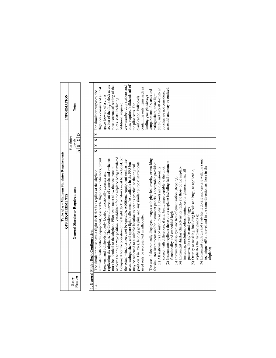
30
14 CFR Ch. I (1–1–24 Edition)
Pt. 60, App. A
VerDate Sep<11>2014
14:00 Mar 14, 2024
Jkt 262047
PO 00000
Frm 00040
Fmt 8010
Sfmt 8006
Q:\14\14V2.TXT
PC31
ER09DE22.000</GPH>
aworley on LAPBH6H6L3 with DISTILLER
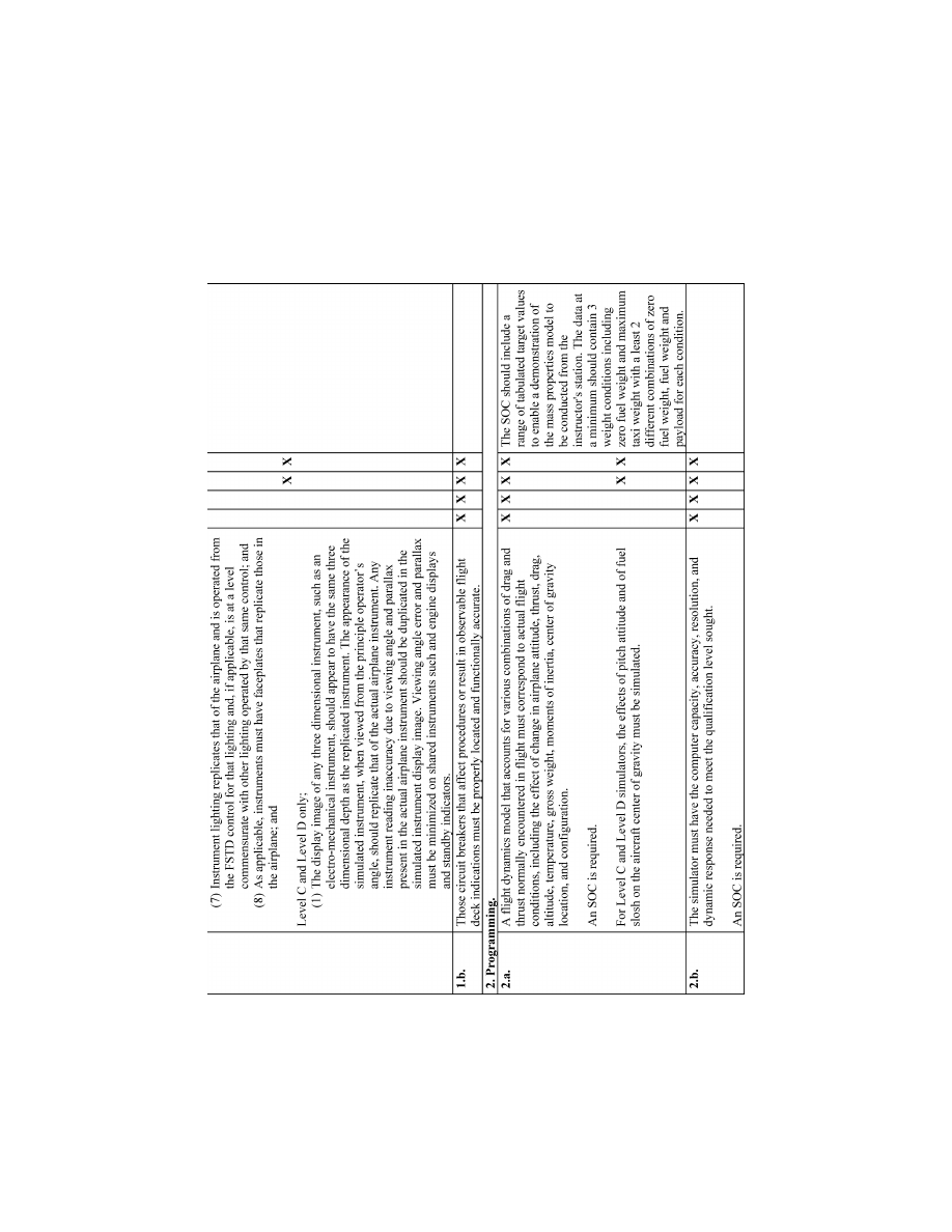
31
Federal Aviation Administration, DOT
Pt. 60, App. A
VerDate Sep<11>2014
14:00 Mar 14, 2024
Jkt 262047
PO 00000
Frm 00041
Fmt 8010
Sfmt 8006
Q:\14\14V2.TXT
PC31
ER09DE22.001</GPH>
aworley on LAPBH6H6L3 with DISTILLER
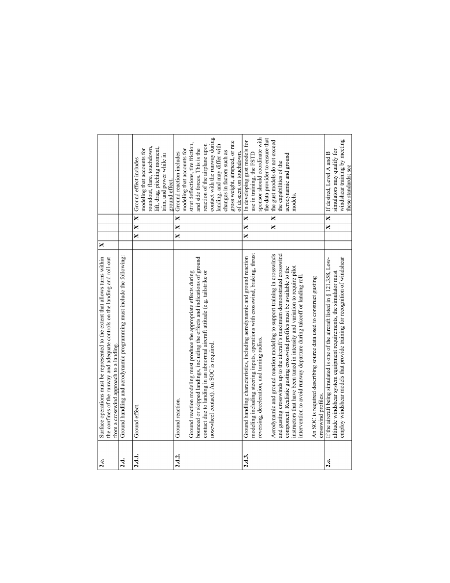
32
14 CFR Ch. I (1–1–24 Edition)
Pt. 60, App. A
VerDate Sep<11>2014
14:00 Mar 14, 2024
Jkt 262047
PO 00000
Frm 00042
Fmt 8010
Sfmt 8006
Q:\14\14V2.TXT
PC31
ER09DE22.002</GPH>
aworley on LAPBH6H6L3 with DISTILLER
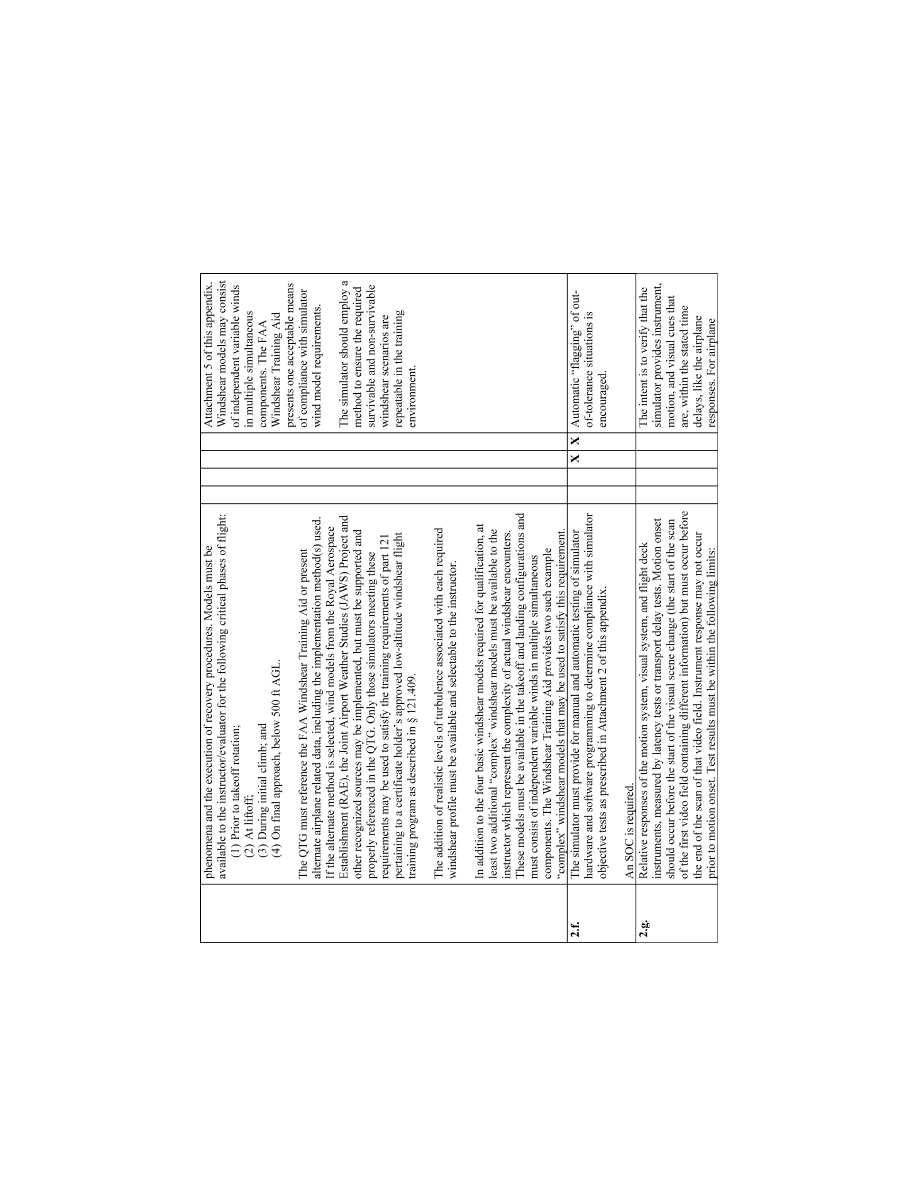
33
Federal Aviation Administration, DOT
Pt. 60, App. A
VerDate Sep<11>2014
14:00 Mar 14, 2024
Jkt 262047
PO 00000
Frm 00043
Fmt 8010
Sfmt 8006
Q:\14\14V2.TXT
PC31
ER09DE22.003</GPH>
aworley on LAPBH6H6L3 with DISTILLER
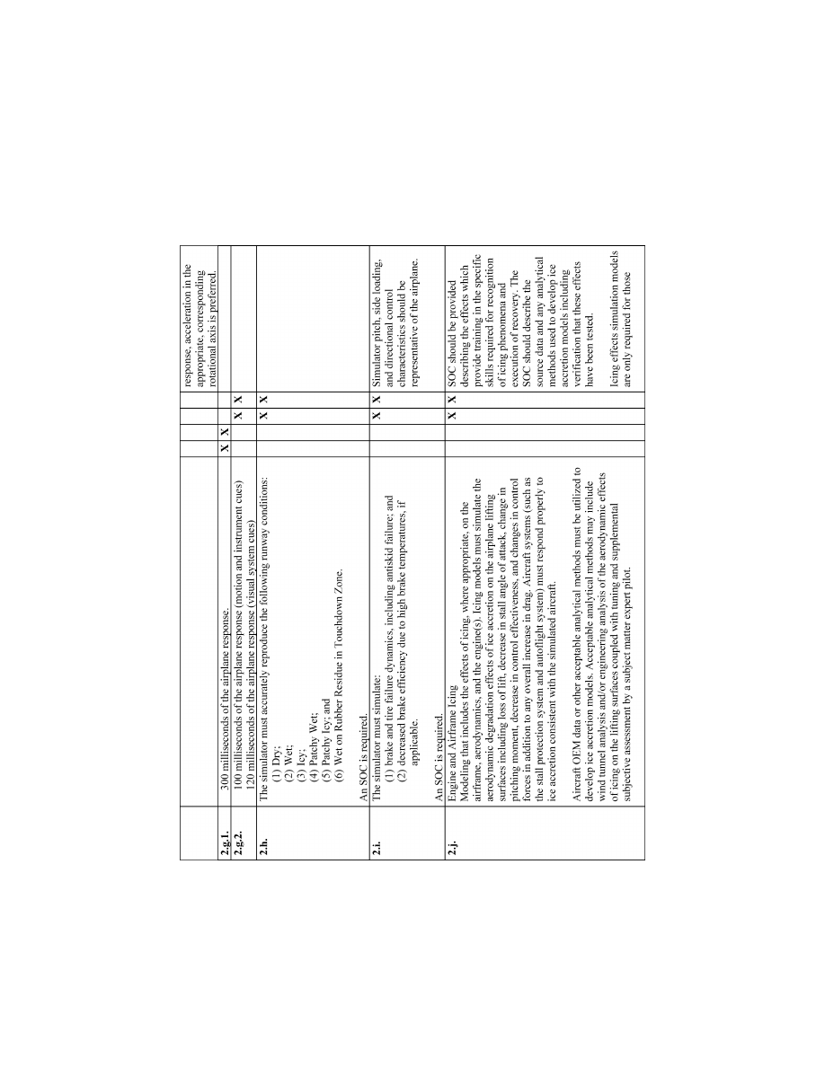
34
14 CFR Ch. I (1–1–24 Edition)
Pt. 60, App. A
VerDate Sep<11>2014
14:00 Mar 14, 2024
Jkt 262047
PO 00000
Frm 00044
Fmt 8010
Sfmt 8006
Q:\14\14V2.TXT
PC31
ER09DE22.004</GPH>
aworley on LAPBH6H6L3 with DISTILLER
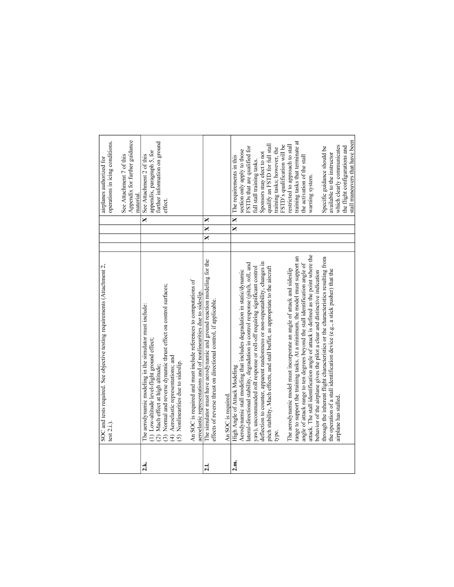
35
Federal Aviation Administration, DOT
Pt. 60, App. A
VerDate Sep<11>2014
14:00 Mar 14, 2024
Jkt 262047
PO 00000
Frm 00045
Fmt 8010
Sfmt 8006
Q:\14\14V2.TXT
PC31
ER09DE22.005</GPH>
aworley on LAPBH6H6L3 with DISTILLER
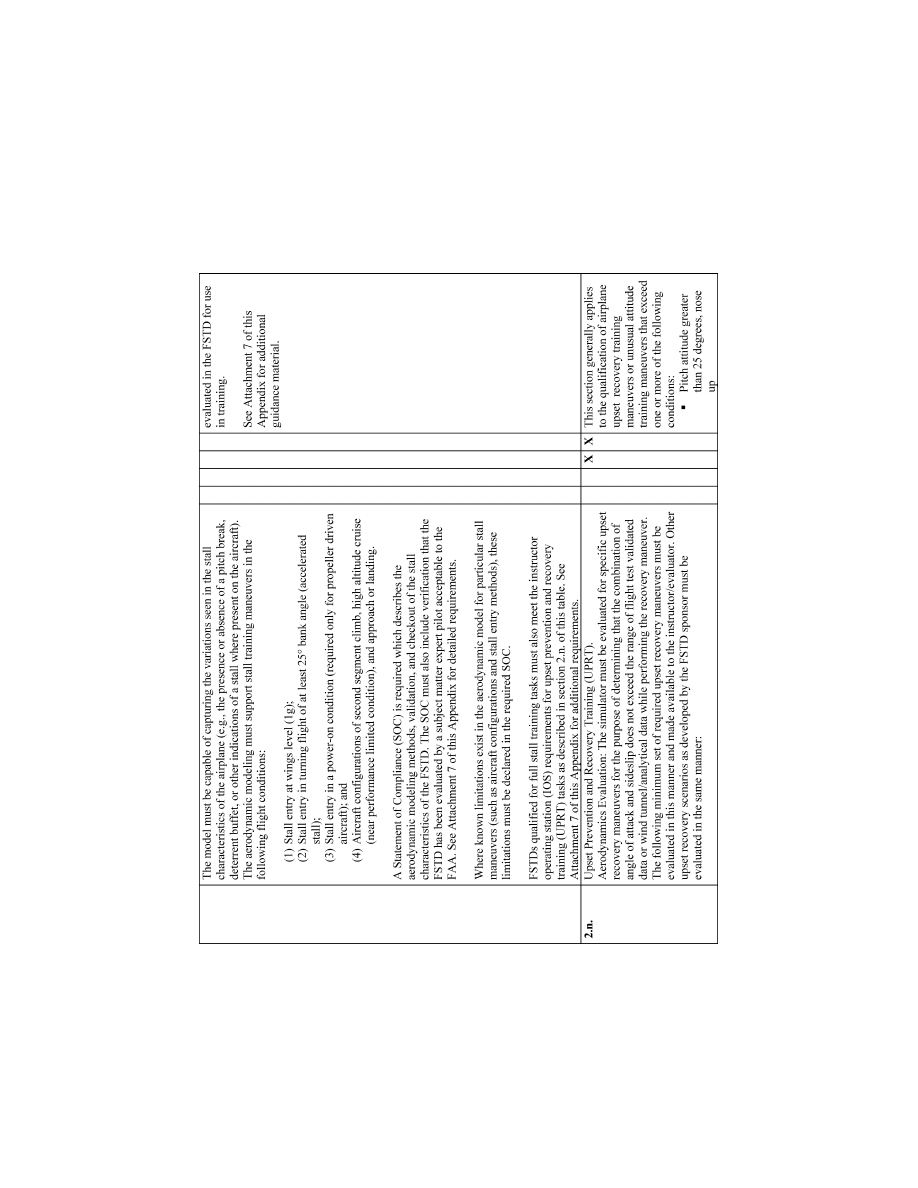
36
14 CFR Ch. I (1–1–24 Edition)
Pt. 60, App. A
VerDate Sep<11>2014
14:00 Mar 14, 2024
Jkt 262047
PO 00000
Frm 00046
Fmt 8010
Sfmt 8006
Q:\14\14V2.TXT
PC31
ER09DE22.006</GPH>
aworley on LAPBH6H6L3 with DISTILLER
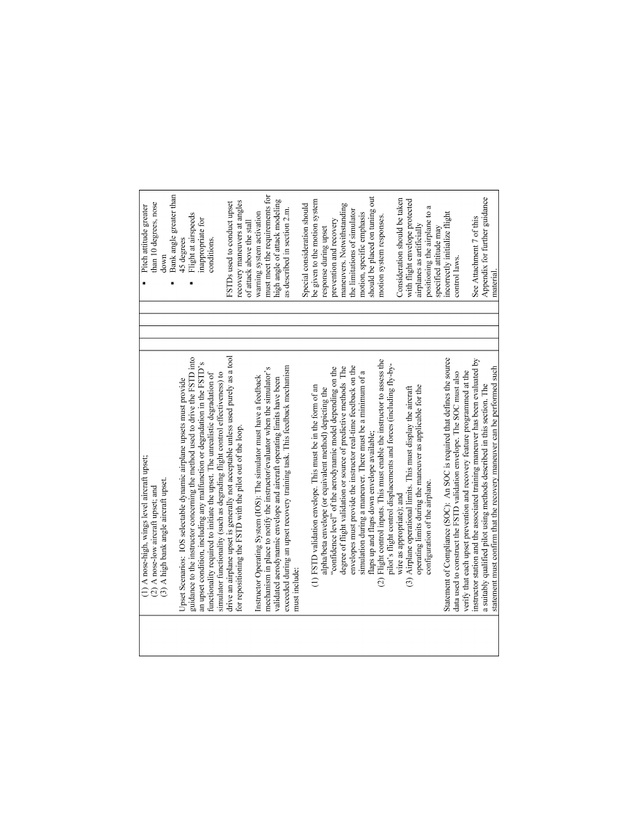
37
Federal Aviation Administration, DOT
Pt. 60, App. A
VerDate Sep<11>2014
14:00 Mar 14, 2024
Jkt 262047
PO 00000
Frm 00047
Fmt 8010
Sfmt 8006
Q:\14\14V2.TXT
PC31
ER09DE22.007</GPH>
aworley on LAPBH6H6L3 with DISTILLER
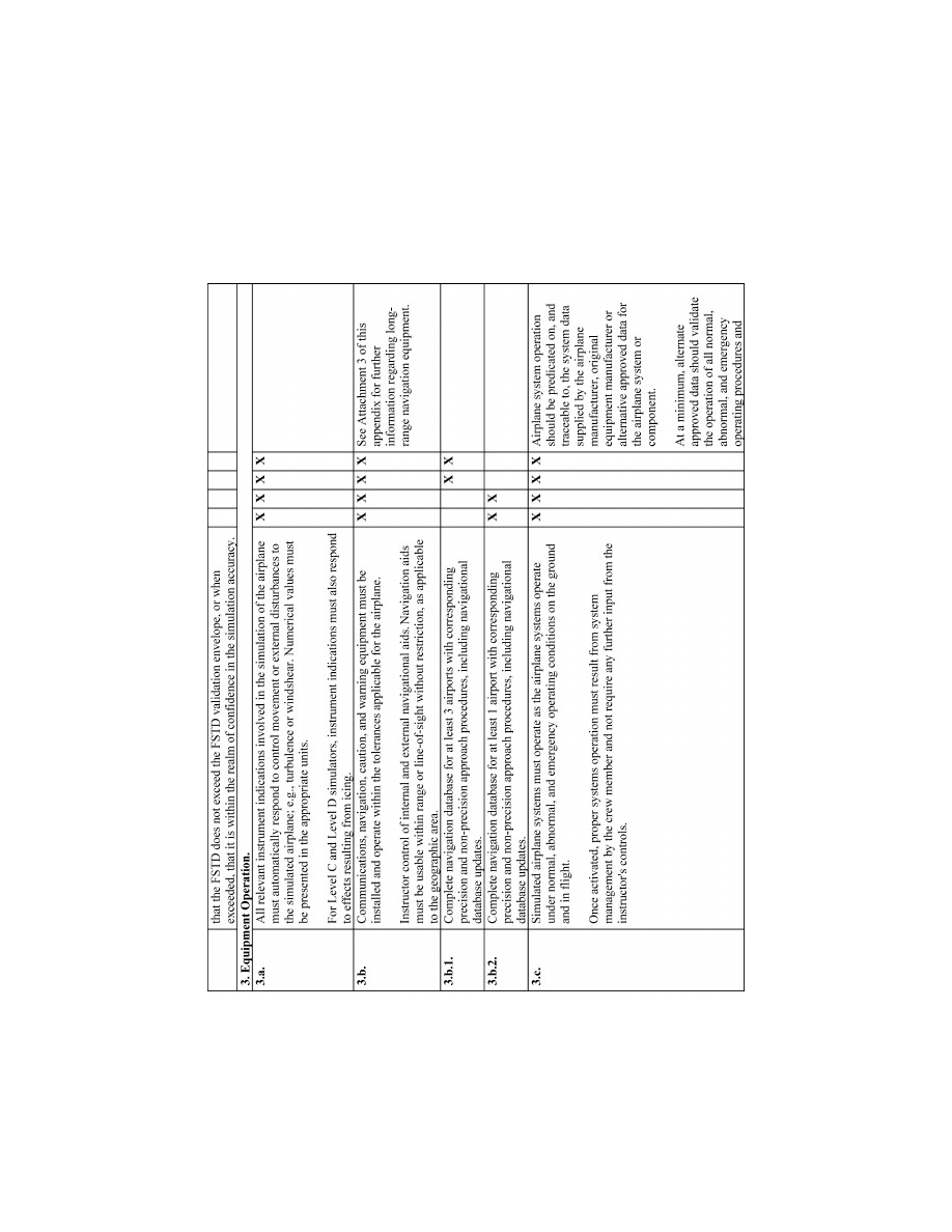
38
14 CFR Ch. I (1–1–24 Edition)
Pt. 60, App. A
VerDate Sep<11>2014
14:00 Mar 14, 2024
Jkt 262047
PO 00000
Frm 00048
Fmt 8010
Sfmt 8006
Q:\14\14V2.TXT
PC31
ER09DE22.008</GPH>
aworley on LAPBH6H6L3 with DISTILLER
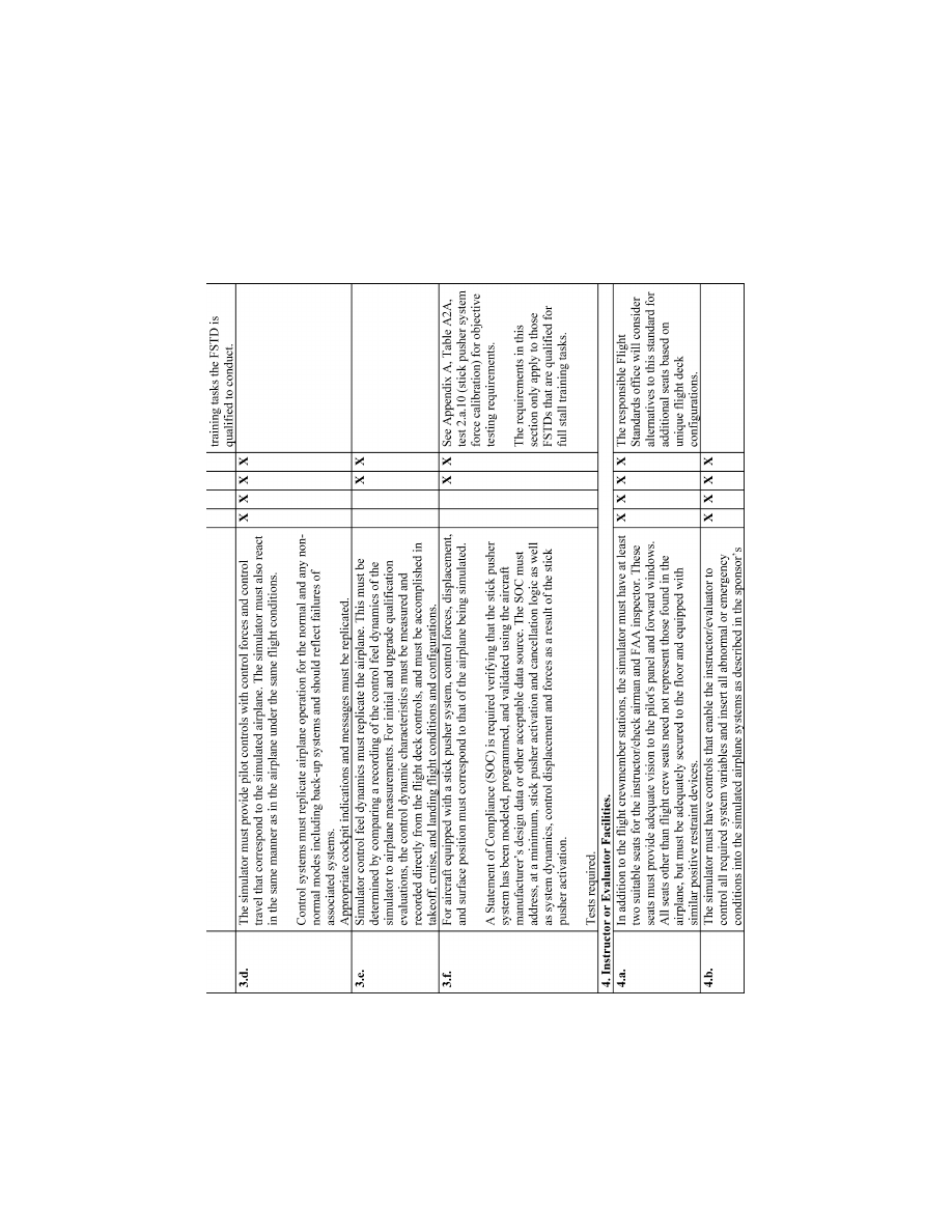
39
Federal Aviation Administration, DOT
Pt. 60, App. A
VerDate Sep<11>2014
14:00 Mar 14, 2024
Jkt 262047
PO 00000
Frm 00049
Fmt 8010
Sfmt 8006
Q:\14\14V2.TXT
PC31
ER09DE22.009</GPH>
aworley on LAPBH6H6L3 with DISTILLER
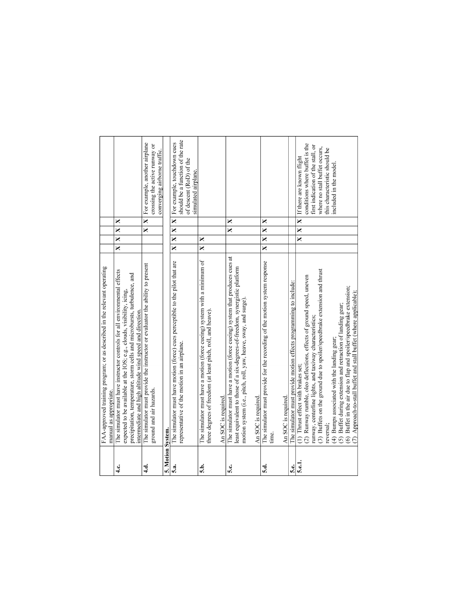
40
14 CFR Ch. I (1–1–24 Edition)
Pt. 60, App. A
VerDate Sep<11>2014
14:00 Mar 14, 2024
Jkt 262047
PO 00000
Frm 00050
Fmt 8010
Sfmt 8006
Q:\14\14V2.TXT
PC31
ER09DE22.010</GPH>
aworley on LAPBH6H6L3 with DISTILLER
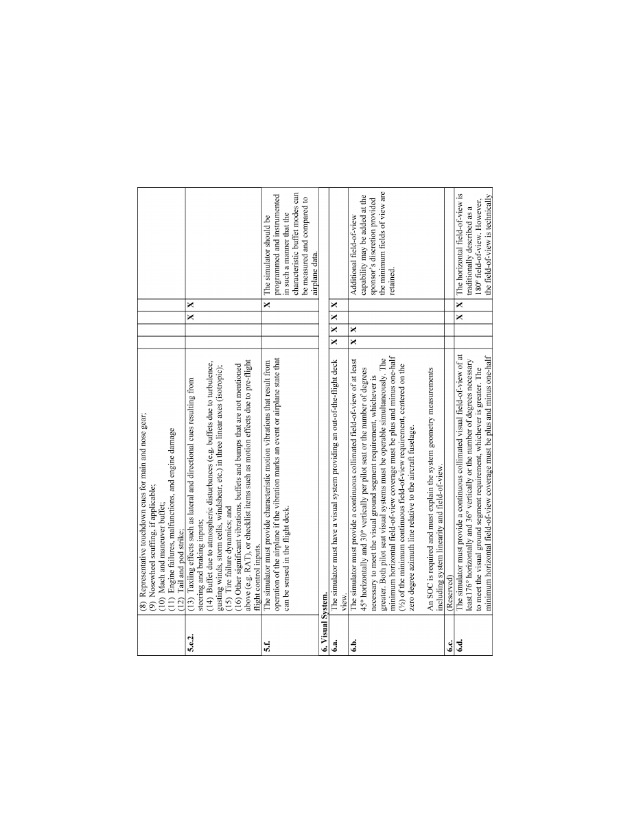
41
Federal Aviation Administration, DOT
Pt. 60, App. A
VerDate Sep<11>2014
14:00 Mar 14, 2024
Jkt 262047
PO 00000
Frm 00051
Fmt 8010
Sfmt 8006
Q:\14\14V2.TXT
PC31
ER09DE22.011</GPH>
aworley on LAPBH6H6L3 with DISTILLER
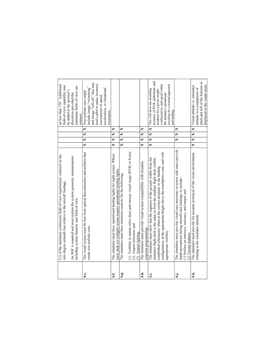
42
14 CFR Ch. I (1–1–24 Edition)
Pt. 60, App. A
VerDate Sep<11>2014
14:00 Mar 14, 2024
Jkt 262047
PO 00000
Frm 00052
Fmt 8010
Sfmt 8006
Q:\14\14V2.TXT
PC31
ER09DE22.012</GPH>
aworley on LAPBH6H6L3 with DISTILLER
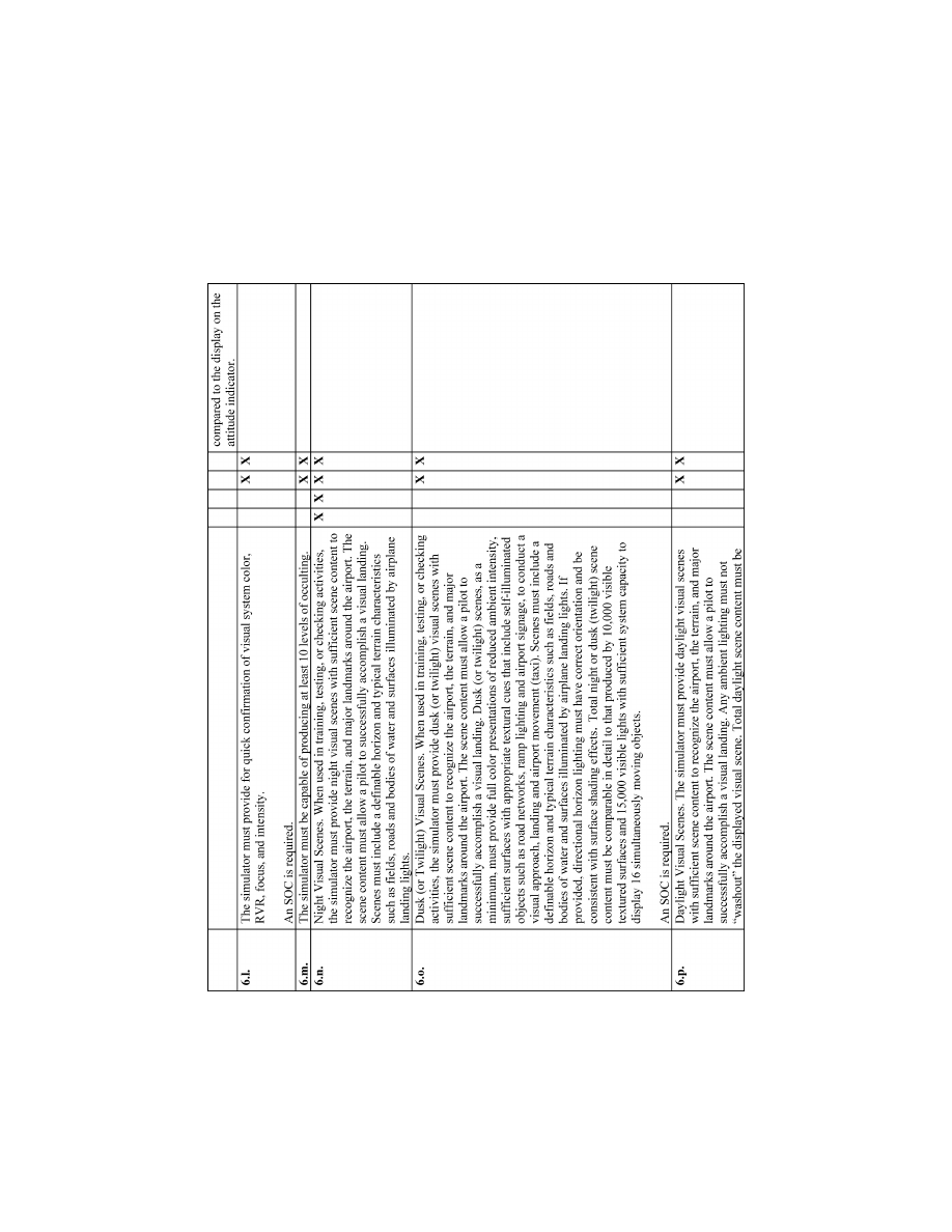
43
Federal Aviation Administration, DOT
Pt. 60, App. A
VerDate Sep<11>2014
14:00 Mar 14, 2024
Jkt 262047
PO 00000
Frm 00053
Fmt 8010
Sfmt 8006
Q:\14\14V2.TXT
PC31
ER09DE22.013</GPH>
aworley on LAPBH6H6L3 with DISTILLER
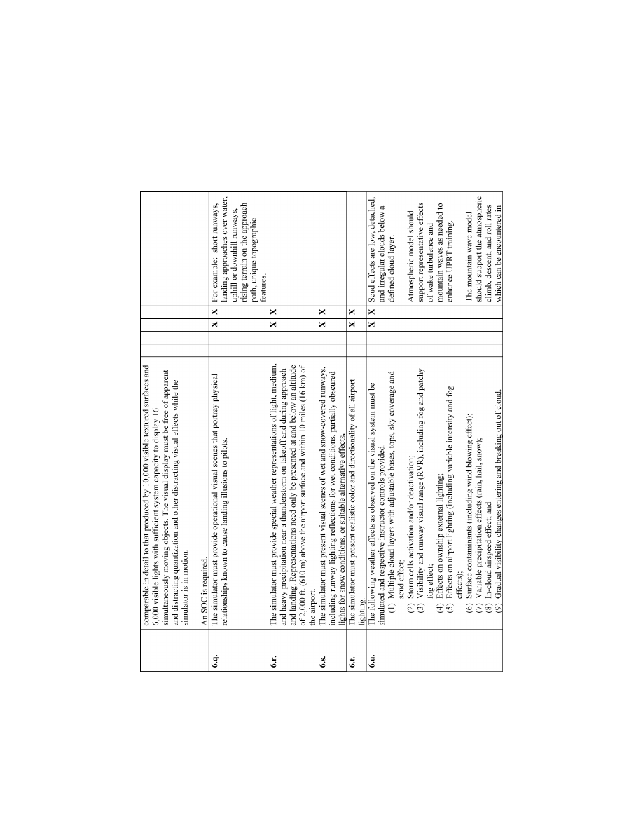
44
14 CFR Ch. I (1–1–24 Edition)
Pt. 60, App. A
VerDate Sep<11>2014
14:00 Mar 14, 2024
Jkt 262047
PO 00000
Frm 00054
Fmt 8010
Sfmt 8006
Q:\14\14V2.TXT
PC31
ER09DE22.014</GPH>
aworley on LAPBH6H6L3 with DISTILLER
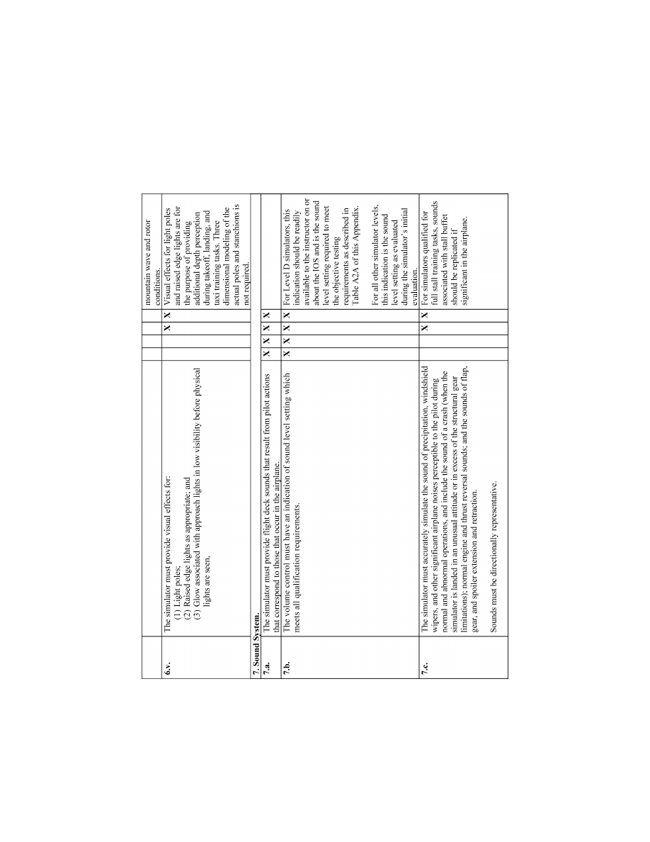
45
Federal Aviation Administration, DOT
Pt. 60, App. A
VerDate Sep<11>2014
14:00 Mar 14, 2024
Jkt 262047
PO 00000
Frm 00055
Fmt 8010
Sfmt 8006
Q:\14\14V2.TXT
PC31
ER09DE22.015</GPH>
aworley on LAPBH6H6L3 with DISTILLER
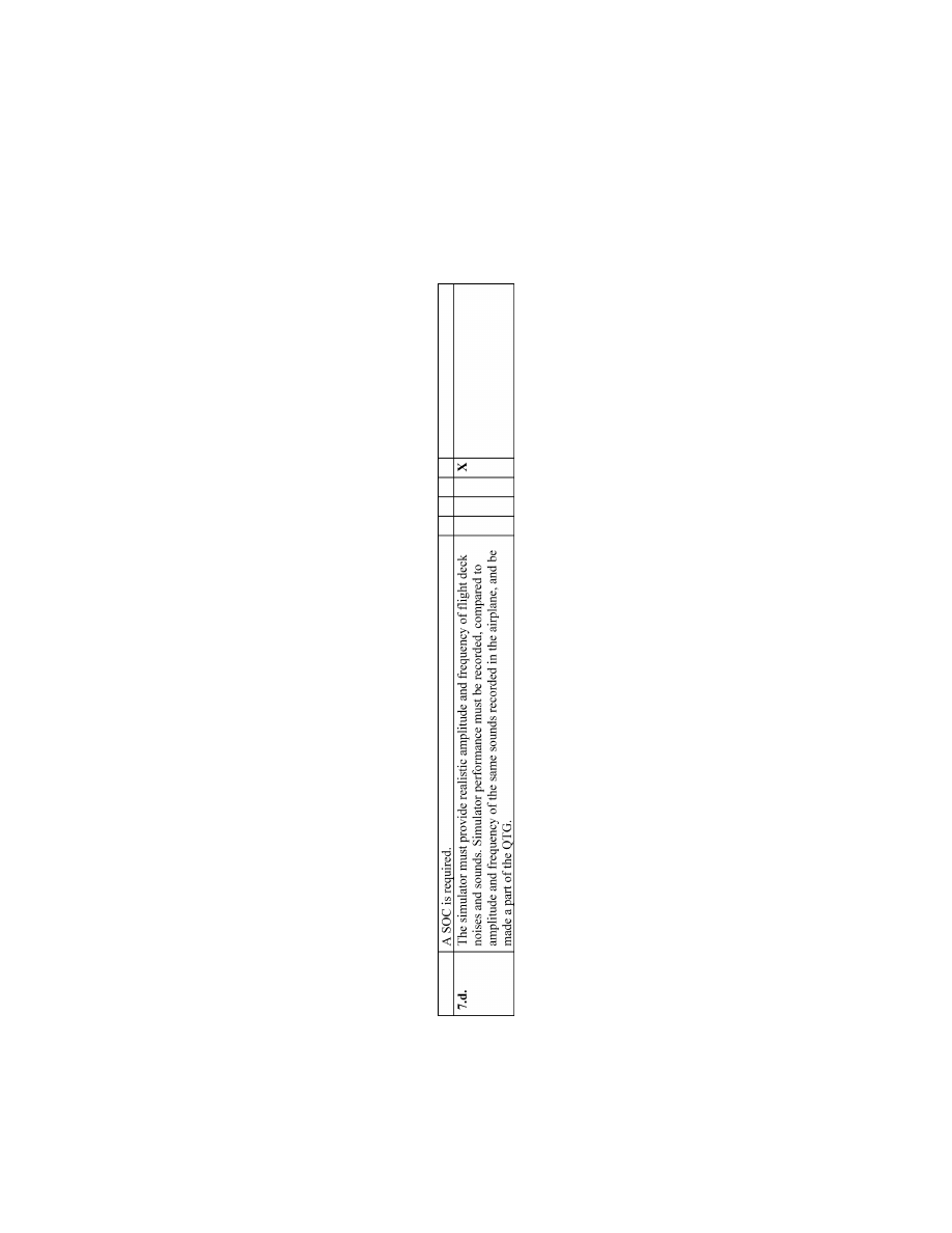
46
14 CFR Ch. I (1–1–24 Edition)
Pt. 60, App. A
VerDate Sep<11>2014
14:00 Mar 14, 2024
Jkt 262047
PO 00000
Frm 00056
Fmt 8010
Sfmt 8006
Q:\14\14V2.TXT
PC31
ER09DE22.016</GPH>
aworley on LAPBH6H6L3 with DISTILLER
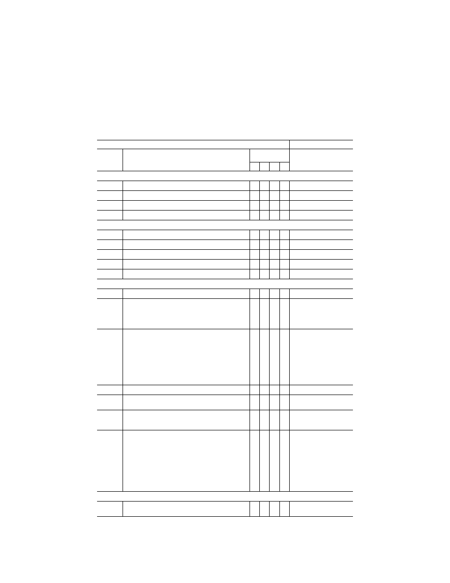
47
Federal Aviation Administration, DOT
Pt. 60, App. A
T
ABLE
A1B—T
ABLE OF
T
ASKS VS
. S
IMULATOR
L
EVEL
QPS requirements
Information
Entry No.
Subjective requirements
In order to be qualified at the simulator qualification level indi-
cated, the simulator must be able to perform at least the
tasks associated with that level of qualification.
Simulator levels
Notes
A B C D
1. Preflight Procedures
1.a. ...........
Preflight Inspection (flight deck only) ........................................
X
X
X
X
1.b. ...........
Engine
Start ..............................................................................
X X X X
1.c. ...........
Taxiing .......................................................................................
R X X
1.d. ...........
Pre-takeoff
Checks ...................................................................
X X X X
2. Takeoff and Departure Phase
2.a. ...........
Normal and Crosswind Takeoff
R
X
X
2.b. ...........
Instrument
Takeoff ....................................................................
X X X X
2.c. ...........
Engine Failure During Takeoff ..................................................
A
X
X
X
2.d. ...........
Rejected
Takeoff .......................................................................
X X X X
2.e. ...........
Departure
Procedure ................................................................
X X X X
3. Inflight Maneuvers
3.a. ...........
Steep
Turns ..............................................................................
X X X X
3.b. High
Angle of
Attack
Maneu-
vers
3.b.1 .........
Approaches
to
Stall ...................................................................
X X X X
3.b.2 .........
Full Stall ....................................................................................
X
X
Stall maneuvers at angles of
attack above the activation
of the stall warning system.
Required only for FSTDs
qualified to conduct full stall
training tasks as indicated
on the Statement of Quali-
fication.
3.c. ...........
Engine
Failure—Multiengine
Airplane ......................................
X X X X
3.d. ...........
Engine Failure—Single-Engine Airplane ..................................
X
X
X
X
3.e. ...........
Specific Flight Characteristics incorporated into the user’s
FAA approved flight training program.
A A A A
3.f. ............
Recovery From Unusual Attitudes ............................................
X
X
X
X
Within the normal flight enve-
lope supported by applicable
simulation validation data.
3.g. ...........
Upset Prevention and Recovery Training (UPRT) ...................
X
X
Upset recovery or unusual atti-
tude training maneuvers
within the FSTD’s validation
envelope that are intended
to exceed pitch attitudes
greater than 25 degrees
nose up; pitch attitudes
greater than 10 degrees
nose down, and bank an-
gles greater than 45 de-
grees.
4. Instrument Procedures
4.a. ...........
Standard Terminal Arrival/Flight Management System Arrivals
Procedures.
X X X X
VerDate Sep<11>2014
14:00 Mar 14, 2024
Jkt 262047
PO 00000
Frm 00057
Fmt 8010
Sfmt 8002
Q:\14\14V2.TXT
PC31
aworley on LAPBH6H6L3 with DISTILLER

48
14 CFR Ch. I (1–1–24 Edition)
Pt. 60, App. A
T
ABLE
A1B—T
ABLE OF
T
ASKS VS
. S
IMULATOR
L
EVEL
—Continued
QPS requirements
Information
Entry No.
Subjective requirements
In order to be qualified at the simulator qualification level indi-
cated, the simulator must be able to perform at least the
tasks associated with that level of qualification.
Simulator levels
Notes
A B C D
4.b. ...........
Holding ......................................................................................
X X X X
4.c. ...........
Precision Instrument.
4.c.1. ........
All Engines Operating ...............................................................
X
X
X
X
e.g., Autopilot, Manual (Flt.
Dir. Assisted), Manual (Raw
Data).
4.c.2. ........
One Engine Inoperative ............................................................
X
X
X
X
e.g., Manual (Flt. Dir. As-
sisted), Manual (Raw Data).
4.d. ...........
Non-Precision Instrument Approach .........................................
X
X
X
X
e.g., NDB, VOR, VOR/DME,
VOR/TAC, RNAV, LOC,
LOC/BC, ADF, and SDF.
4.e. ...........
Circling Approach ......................................................................
X
X
X
X
Specific authorization required.
4.f. ............
Missed Approach.
4.f.1. .........
Normal .......................................................................................
X X X X
4.f.2. .........
One
Engine
Inoperative ............................................................
X X X X
5. Landings and Approaches to Landings
5.a. ...........
Normal and Crosswind Approaches and Landings ..................
R
X
X
5.b. ...........
Landing From a Precision/Non-Precision Approach ................
R
X
X
5.c. ...........
Approach and Landing with (Simulated) Engine Failure—Mul-
tiengine Airplane.
....
R X X
5.d. ...........
Landing From Circling Approach ..............................................
R
X
X
5.e. ...........
Rejected
Landing ......................................................................
X X X X
5.f. ............
Landing From a No Flap or a Nonstandard Flap Configuration
Approach.
R X X
6. Normal and Abnormal Procedures
6.a. ...........
Engine (including shutdown and restart) ..................................
X
X
X
X
6.b. ...........
Fuel
System ..............................................................................
X X X X
6.c. ...........
Electrical
System ......................................................................
X X X X
6.d. ...........
Hydraulic
System ......................................................................
X X X X
6.e. ...........
Environmental and Pressurization Systems .............................
X
X
X
X
6.f. ............
Fire Detection and Extinguisher Systems ................................
X
X
X
X
6.g. ...........
Navigation and Avionics Systems ............................................
X
X
X
X
6.h. ...........
Automatic Flight Control System, Electronic Flight Instrument
System, and Related Subsystems.
X X X X
6.i. ............
Flight Control Systems ..............................................................
X
X
X
X
6.j. ............
Anti-ice and Deice Systems ......................................................
X
X
X
X
6.k. ...........
Aircraft and Personal Emergency Equipment ..........................
X
X
X
X
7. Emergency Procedures
7.a. ...........
Emergency Descent (Max. Rate) .............................................
X
X
X
X
VerDate Sep<11>2014
14:00 Mar 14, 2024
Jkt 262047
PO 00000
Frm 00058
Fmt 8010
Sfmt 8002
Q:\14\14V2.TXT
PC31
aworley on LAPBH6H6L3 with DISTILLER
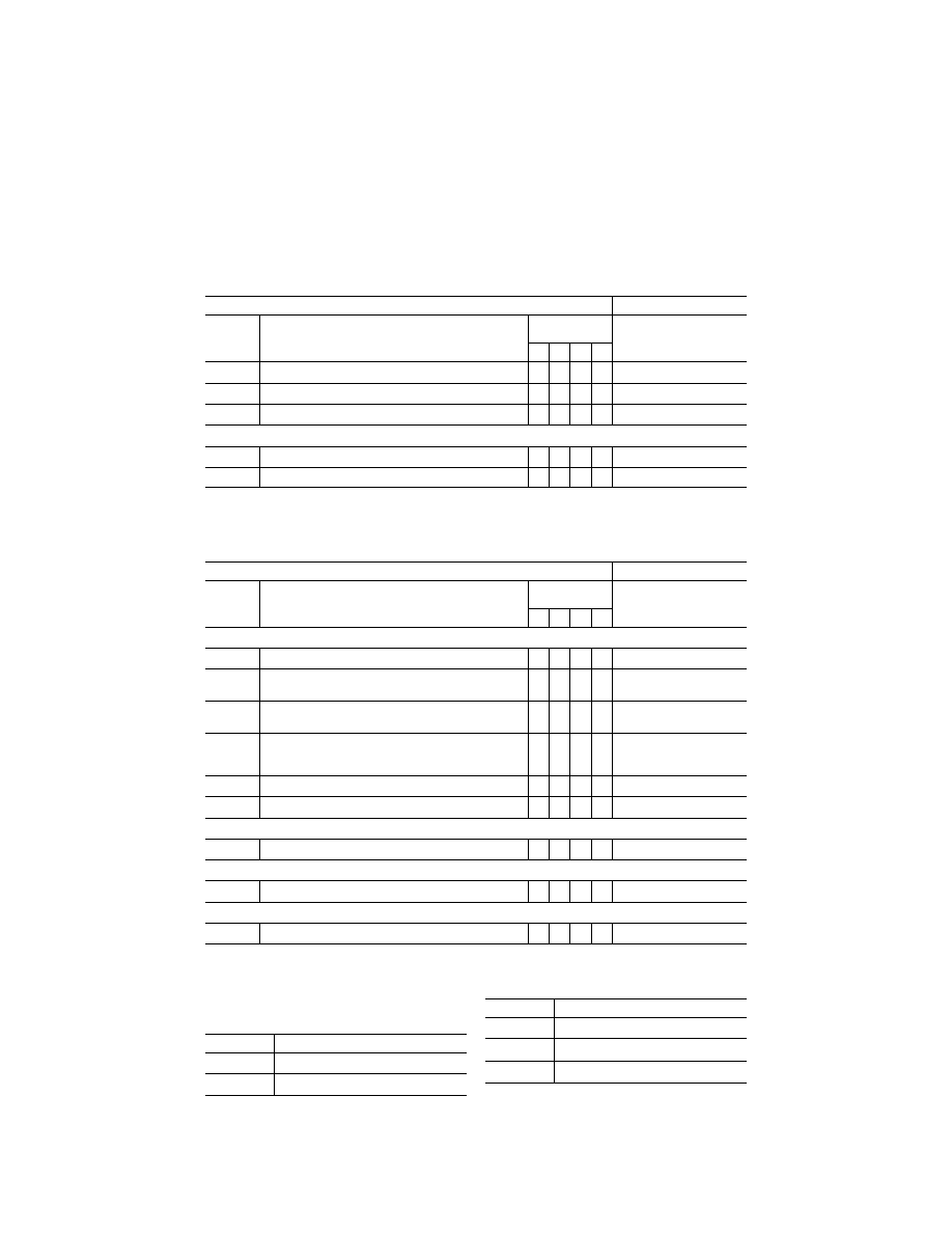
49
Federal Aviation Administration, DOT
Pt. 60, App. A
T
ABLE
A1B—T
ABLE OF
T
ASKS VS
. S
IMULATOR
L
EVEL
—Continued
QPS requirements
Information
Entry No.
Subjective requirements
In order to be qualified at the simulator qualification level indi-
cated, the simulator must be able to perform at least the
tasks associated with that level of qualification.
Simulator levels
Notes
A B C D
7.b. ...........
Inflight Fire and Smoke Removal .............................................
X
X
X
X
7.c. ...........
Rapid
Decompression ...............................................................
X X X X
7.d. ...........
Emergency
Evacuation .............................................................
X X X X
8. Postflight Procedures
8.a. ...........
After-Landing
Procedures .........................................................
X X X X
8.b. ...........
Parking
and
Securing ...............................................................
X X X X
‘‘A’’—indicates that the system, task, or procedure may be examined if the appropriate aircraft system or control is simulated in
the FSTD and is working properly.
‘‘R’’—indicates that the simulator may be qualified for this task for continuing qualification training.
‘‘X’’—indicates that the simulator must be able to perform this task for this level of qualification.
T
ABLE
A1C—T
ABLE OF
S
IMULATOR
S
YSTEM
T
ASKS
QPS requirements
Information
Entry No.
Subjective requirements
In order to be qualified at the simulator qualification level indi-
cated, the simulator must be able to perform at least the
tasks associated with that level of qualification.
Simulator levels
Notes
A B C D
1. Instructor Operating Station (IOS), as appropriate
1.a. ...........
Power
switch(es) .......................................................................
X X X X
1.b. ...........
Airplane conditions ....................................................................
X
X
X
X
e.g., GW, CG, Fuel loading
and Systems.
1.c. ...........
Airports/Runways ......................................................................
X X X X e.g.,
Selection,
Surface,
Presets, Lighting controls.
1.d. ...........
Environmental
controls .............................................................
X X X X e.g.,
Clouds,
Visibility, RVR,
Temp, Wind, Ice, Snow,
Rain, and Windshear.
1.e. ...........
Airplane system malfunctions (Insertion/deletion) ....................
X
X
X
X
1.f. ............
Locks, Freezes, and Repositioning ..........................................
X
X
X
X
2. Sound Controls
2.a. ...........
On/off/adjustment ......................................................................
X X X X
3. Motion/Control Loading System
3.a. ...........
On/off/emergency
stop ..............................................................
X X X X
4. Observer Seats/Stations
4.a. ...........
Position/Adjustment/Positive restraint system ..........................
X
X
X
X
A
TTACHMENT
2
TO
A
PPENDIX
A
TO
P
ART
60—
FFS O
BJECTIVE
T
ESTS
T
ABLE OF
C
ONTENTS
Paragraph No.
Title
1. ....................
Introduction.
2. ....................
Test Requirements.
T
ABLE OF
C
ONTENTS
—Continued
Paragraph No.
Title
Table A2A, Objective Tests.
3. ....................
General.
4. ....................
Control Dynamics.
VerDate Sep<11>2014
14:00 Mar 14, 2024
Jkt 262047
PO 00000
Frm 00059
Fmt 8010
Sfmt 8002
Q:\14\14V2.TXT
PC31
aworley on LAPBH6H6L3 with DISTILLER

50
14 CFR Ch. I (1–1–24 Edition)
Pt. 60, App. A
T
ABLE OF
C
ONTENTS
—Continued
Paragraph No.
Title
5. ....................
Ground Effect.
6. ....................
Motion System.
7. ....................
Sound System.
8. ....................
Additional Information About Flight Simulator
Qualification for New or Derivative Air-
planes.
9. ....................
Engineering Simulator—Validation Data.
10. ..................
[Reserved]
11. ..................
Validation Test Tolerances.
12. ..................
Validation Data Roadmap.
13. ..................
Acceptance Guidelines for Alternative En-
gines Data.
14. ..................
Acceptance Guidelines for Alternative Avi-
onics (Flight-Related Computers and Con-
trollers).
15. ..................
Transport Delay Testing.
16. ..................
Continuing Qualification Evaluations—Vali-
dation Test Data Presentation.
17. ..................
Alternative Data Sources, Procedures, and
Instrumentation: Level A and Level B Sim-
ulators Only.
llllllllllllllllllllllll
B
EGIN
I
NFORMATION
1. I
NTRODUCTION
a. For the purposes of this attachment, the
flight conditions specified in the Flight Con-
ditions Column of Table A2A of this appen-
dix, are defined as follows:
(1) Ground—on ground, independent of air-
plane configuration;
(2) Take-off—gear down with flaps/slats in
any certified takeoff position;
(3) First segment climb—gear down with
flaps/slats in any certified takeoff position
(normally not above 50 ft AGL);
(4) Second segment climb—gear up with
flaps/slats in any certified takeoff position
(normally between 50 ft and 400 ft AGL);
(5) Clean—flaps/slats retracted and gear up;
(6) Cruise—clean configuration at cruise
altitude and airspeed;
(7) Approach—gear up or down with flaps/
slats at any normal approach position as rec-
ommended by the airplane manufacturer;
and
(8) Landing—gear down with flaps/slats in
any certified landing position.
b. The format for numbering the objective
tests in Appendix A, Attachment 2, Table
A2A, and the objective tests in Appendix B,
Attachment 2, Table B2A, is identical. How-
ever, each test required for FFSs is not nec-
essarily required for FTDs. Also, each test
required for FTDs is not necessarily required
for FFSs. Therefore, when a test number (or
series of numbers) is not required, the term
‘‘Reserved’’ is used in the table at that loca-
tion. Following this numbering format pro-
vides a degree of commonality between the
two tables and substantially reduces the po-
tential for confusion when referring to objec-
tive test numbers for either FFSs or FTDs.
c. The reader is encouraged to review the
Airplane Flight Simulator Evaluation Hand-
book, Volumes I and II, published by the
Royal Aeronautical Society, London, UK,
and AC 25–7, as amended, Flight Test Guide
for Certification of Transport Category Air-
planes, and AC 23–8, as amended, Flight Test
Guide for Certification of Part 23 Airplanes,
for references and examples regarding flight
testing requirements and techniques.
d. If relevant winds are present in the ob-
jective data, the wind vector should be clear-
ly noted as part of the data presentation, ex-
pressed in conventional terminology, and re-
lated to the runway being used for the test.
E
ND
I
NFORMATION
llllllllllllllllllllllll
B
EGIN
QPS R
EQUIREMENTS
2. T
EST
R
EQUIREMENTS
a. The ground and flight tests required for
qualification are listed in Table A2A, FFS
Objective Tests. Computer generated simu-
lator test results must be provided for each
test except where an alternative test is spe-
cifically authorized by the responsible Flight
Standards office. If a flight condition or op-
erating condition is required for the test but
does not apply to the airplane being simu-
lated or to the qualification level sought, it
may be disregarded (e.g., an engine out
missed approach for a single-engine airplane
or a maneuver using reverse thrust for an
airplane without reverse thrust capability).
Each test result is compared against the val-
idation data described in § 60.13 and in this
appendix. Although use of a driver program
designed to automatically accomplish the
tests is encouraged for all simulators and re-
quired for Level C and Level D simulators, it
must be possible to conduct each test manu-
ally while recording all appropriate param-
eters. The results must be produced on an
appropriate recording device acceptable to
the responsible Flight Standards office and
must include simulator number, date, time,
conditions, tolerances, and appropriate de-
pendent variables portrayed in comparison
to the validation data. Time histories are re-
quired unless otherwise indicated in Table
A2A. All results must be labeled using the
tolerances and units given.
b. Table A2A in this attachment sets out
the test results required, including the pa-
rameters, tolerances, and flight conditions
VerDate Sep<11>2014
14:00 Mar 14, 2024
Jkt 262047
PO 00000
Frm 00060
Fmt 8010
Sfmt 8002
Q:\14\14V2.TXT
PC31
aworley on LAPBH6H6L3 with DISTILLER

51
Federal Aviation Administration, DOT
Pt. 60, App. A
for simulator validation. Tolerances are pro-
vided for the listed tests because mathe-
matical modeling and acquisition and devel-
opment of reference data are often inexact.
All tolerances listed in the following tables
are applied to simulator performance. When
two tolerance values are given for a param-
eter, the less restrictive may be used unless
otherwise indicated. In those cases where a
tolerance is expressed only as a percentage,
the tolerance percentage applies to the max-
imum value of that parameter within its
normal operating range as measured from
the neutral or zero position unless otherwise
indicated.
c. Certain tests included in this attach-
ment must be supported with an SOC. In
Table A2A, requirements for SOCs are indi-
cated in the ‘‘Test Details’’ column.
d. When operational or engineering judg-
ment is used in making assessments for
flight test data applications for simulator
validity, such judgment must not be limited
to a single parameter. For example, data
that exhibit rapid variations of the measured
parameters may require interpolations or a
‘‘best fit’’ data selection. All relevant param-
eters related to a given maneuver or flight
condition must be provided to allow overall
interpretation. When it is difficult or impos-
sible to match simulator to airplane data
throughout a time history, differences must
be justified by providing a comparison of
other related variables for the condition
being assessed.
e. It is not acceptable to program the FFS
so that the mathematical modeling is cor-
rect only at the validation test points. Un-
less otherwise noted, simulator tests must
represent airplane performance and handling
qualities at operating weights and centers of
gravity (CG) typical of normal operation.
Simulator tests at extreme weight or CG
conditions may be acceptable where required
for concurrent aircraft certification testing.
Tests of handling qualities must include val-
idation of augmentation devices.
f. When comparing the parameters listed to
those of the airplane, sufficient data must
also be provided to verify the correct flight
condition and airplane configuration
changes. For example, to show that control
force is within the parameters for a static
stability test, data to show the correct air-
speed, power, thrust or torque, airplane con-
figuration, altitude, and other appropriate
datum identification parameters must also
be given. If comparing short period dynam-
ics, normal acceleration may be used to es-
tablish a match to the airplane, but airspeed,
altitude, control input, airplane configura-
tion, and other appropriate data must also
be given. If comparing landing gear change
dynamics, pitch, airspeed, and altitude may
be used to establish a match to the airplane,
but landing gear position must also be pro-
vided. All airspeed values must be properly
annotated (e.g., indicated versus calibrated).
In addition, the same variables must be used
for comparison (e.g., compare inches to
inches rather than inches to centimeters).
g. The QTG provided by the sponsor must
clearly describe how the simulator will be
set up and operated for each test. Each simu-
lator subsystem may be tested independ-
ently, but overall integrated testing of the
simulator must be accomplished to assure
that the total simulator system meets the
prescribed standards. A manual test proce-
dure with explicit and detailed steps for
completing each test must also be provided.
h. For previously qualified simulators, the
tests and tolerances of this attachment may
be used in subsequent continuing qualifica-
tion evaluations for any given test if the
sponsor has submitted a proposed MQTG re-
vision to the responsible Flight Standards
office and has received responsible Flight
Standards office approval.
i. Simulators are evaluated and qualified
with an engine model simulating the air-
plane data supplier’s flight test engine. For
qualification of alternative engine models
(either variations of the flight test engines
or other manufacturer’s engines) additional
tests with the alternative engine models
may be required. This attachment contains
guidelines for alternative engines.
j. For testing Computer Controlled Air-
craft (CCA) simulators, or other highly aug-
mented airplane simulators, flight test data
is required for the Normal (N) and/or Non-
normal (NN) control states, as indicated in
this attachment. Where test results are inde-
pendent of control state, Normal or Non-nor-
mal control data may be used. All tests in
Table A2A require test results in the Normal
control state unless specifically noted other-
wise in the Test Details section following the
CCA designation. The responsible Flight
Standards office will determine what tests
are appropriate for airplane simulation data.
When making this determination, the re-
sponsible Flight Standards office may re-
quire other levels of control state degrada-
tion for specific airplane tests. Where Non-
normal control states are required, test data
must be provided for one or more Non-nor-
mal control states, and must include the
least augmented state. Where applicable,
flight test data must record Normal and
Non-normal states for:
(1) Pilot controller deflections or electroni-
cally generated inputs, including location of
input; and
(2) Flight control surface positions unless
test results are not affected by, or are inde-
pendent of, surface positions.
k. Tests of handling qualities must include
validation of augmentation devices. FFSs for
highly augmented airplanes will be validated
both in the unaugmented configuration (or
failure state with the maximum permitted
degradation in handling qualities) and the
VerDate Sep<11>2014
14:00 Mar 14, 2024
Jkt 262047
PO 00000
Frm 00061
Fmt 8010
Sfmt 8002
Q:\14\14V2.TXT
PC31
aworley on LAPBH6H6L3 with DISTILLER

52
14 CFR Ch. I (1–1–24 Edition)
Pt. 60, App. A
augmented configuration. Where various lev-
els of handling qualities result from failure
states, validation of the effect of the failure
is necessary. Requirements for testing will
be mutually agreed to between the sponsor
and the responsible Flight Standards office
on a case-by-case basis.
l. Some tests will not be required for air-
planes using airplane hardware in the simu-
lator flight deck (e.g., ‘‘side stick con-
troller’’). These exceptions are noted in Sec-
tion 2 ‘‘Handling Qualities’’ in Table A2A of
this attachment. However, in these cases,
the sponsor must provide a statement that
the airplane hardware meets the appropriate
manufacturer’s specifications and the spon-
sor must have supporting information to
that fact available for responsible Flight
Standards office review.
m. For objective test purposes, see Appen-
dix F of this part for the definitions of ‘‘Near
maximum,’’ ‘‘Light,’’ and ‘‘Medium’’ gross
weight.
E
ND
QPS R
EQUIREMENTS
llllllllllllllllllllllll
B
EGIN
I
NFORMATION
n. In those cases where the objective test
results authorize a ‘‘snapshot test’’ or a ‘‘se-
ries of snapshot tests’’ results in lieu of a
time-history result, the sponsor or other
data provider must ensure that a steady
state condition exists at the instant of time
captured by the ‘‘snapshot.’’ The steady
state condition should exist from 4 seconds
prior to, through 1 second following, the in-
stant of time captured by the snap shot.
o. For references on basic operating
weight, see AC 120–27, ‘‘Aircraft Weight and
Balance;’’ and FAA–H–8083–1, ‘‘Aircraft
Weight and Balance Handbook.’’
E
ND
I
NFORMATION
llllllllllllllllllllllll
VerDate Sep<11>2014
14:00 Mar 14, 2024
Jkt 262047
PO 00000
Frm 00062
Fmt 8010
Sfmt 8002
Q:\14\14V2.TXT
PC31
aworley on LAPBH6H6L3 with DISTILLER
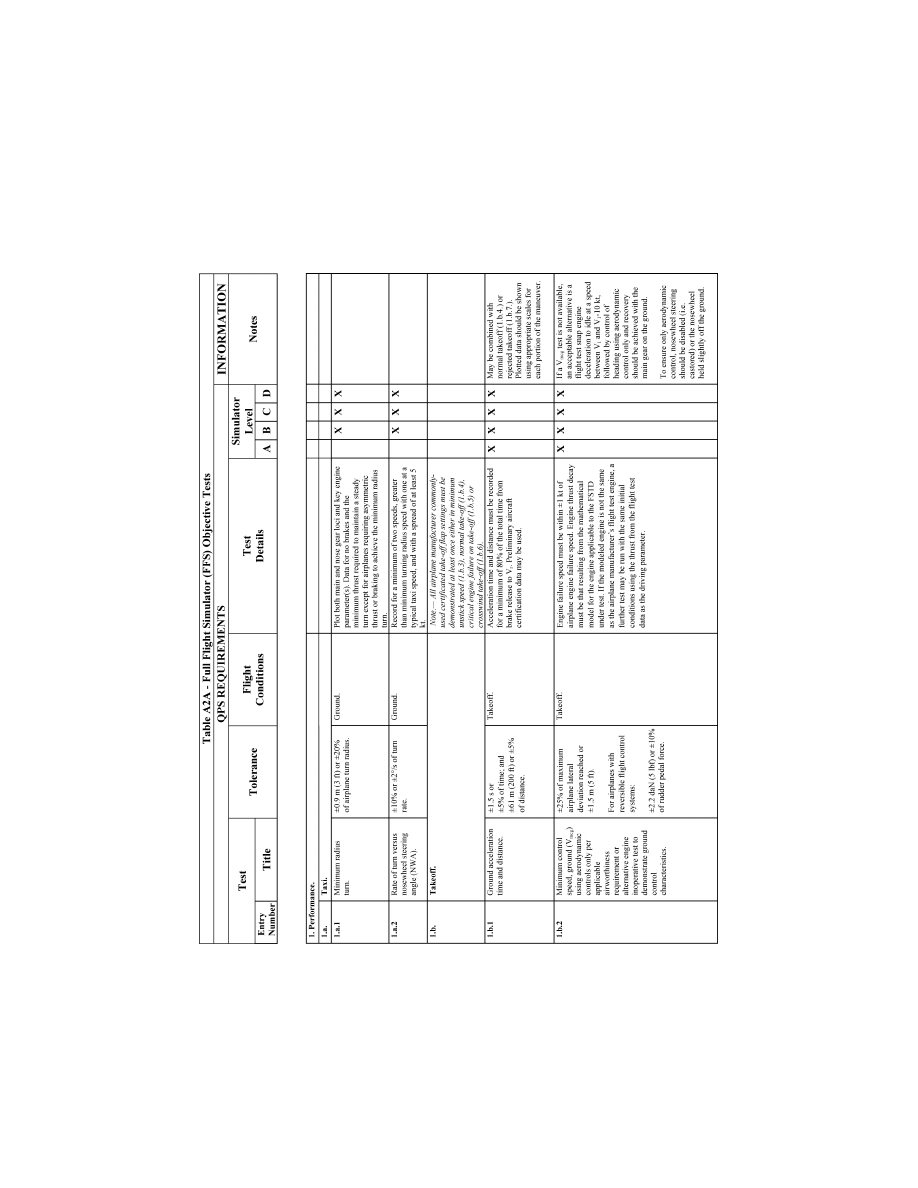
53
Federal Aviation Administration, DOT
Pt. 60, App. A
VerDate Sep<11>2014
14:00 Mar 14, 2024
Jkt 262047
PO 00000
Frm 00063
Fmt 8010
Sfmt 8006
Q:\14\14V2.TXT
PC31
ER09DE22.017</GPH>
aworley on LAPBH6H6L3 with DISTILLER
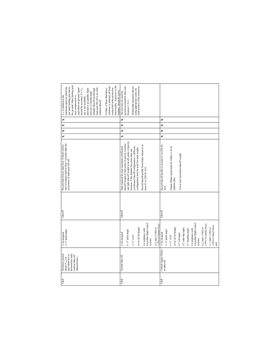
54
14 CFR Ch. I (1–1–24 Edition)
Pt. 60, App. A
VerDate Sep<11>2014
14:00 Mar 14, 2024
Jkt 262047
PO 00000
Frm 00064
Fmt 8010
Sfmt 8006
Q:\14\14V2.TXT
PC31
ER09DE22.018</GPH>
aworley on LAPBH6H6L3 with DISTILLER
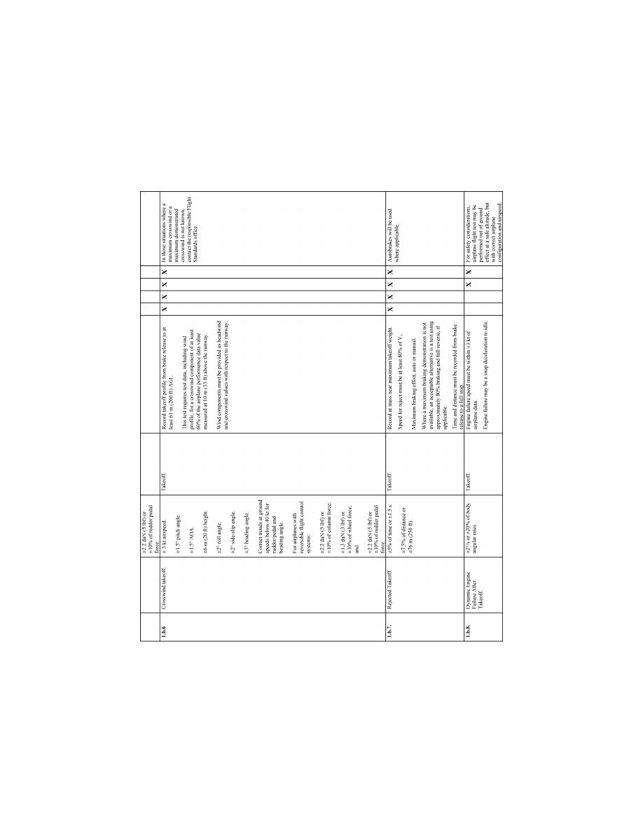
55
Federal Aviation Administration, DOT
Pt. 60, App. A
VerDate Sep<11>2014
14:00 Mar 14, 2024
Jkt 262047
PO 00000
Frm 00065
Fmt 8010
Sfmt 8006
Q:\14\14V2.TXT
PC31
ER09DE22.019</GPH>
aworley on LAPBH6H6L3 with DISTILLER
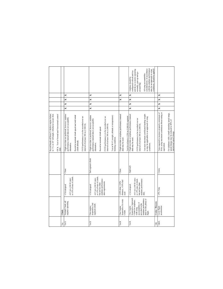
56
14 CFR Ch. I (1–1–24 Edition)
Pt. 60, App. A
VerDate Sep<11>2014
14:00 Mar 14, 2024
Jkt 262047
PO 00000
Frm 00066
Fmt 8010
Sfmt 8006
Q:\14\14V2.TXT
PC31
ER09DE22.020</GPH>
aworley on LAPBH6H6L3 with DISTILLER
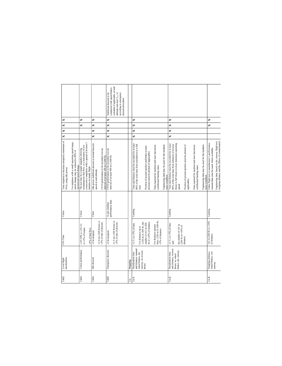
57
Federal Aviation Administration, DOT
Pt. 60, App. A
VerDate Sep<11>2014
14:00 Mar 14, 2024
Jkt 262047
PO 00000
Frm 00067
Fmt 8010
Sfmt 8006
Q:\14\14V2.TXT
PC31
ER09DE22.021</GPH>
aworley on LAPBH6H6L3 with DISTILLER
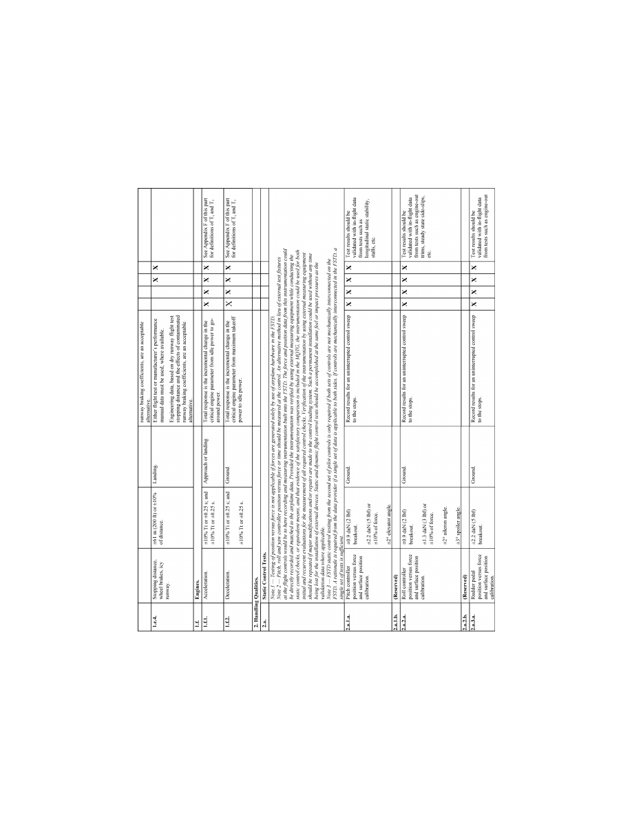
58
14 CFR Ch. I (1–1–24 Edition)
Pt. 60, App. A
VerDate Sep<11>2014
14:00 Mar 14, 2024
Jkt 262047
PO 00000
Frm 00068
Fmt 8010
Sfmt 8006
Q:\14\14V2.TXT
PC31
ER09DE22.022</GPH>
aworley on LAPBH6H6L3 with DISTILLER
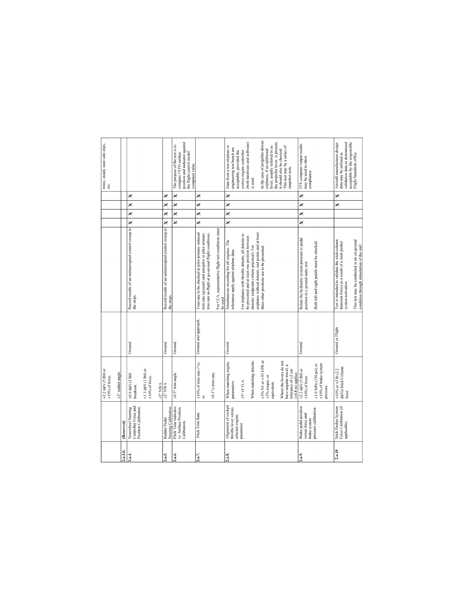
59
Federal Aviation Administration, DOT
Pt. 60, App. A
VerDate Sep<11>2014
14:00 Mar 14, 2024
Jkt 262047
PO 00000
Frm 00069
Fmt 8010
Sfmt 8006
Q:\14\14V2.TXT
PC31
ER09DE22.023</GPH>
aworley on LAPBH6H6L3 with DISTILLER
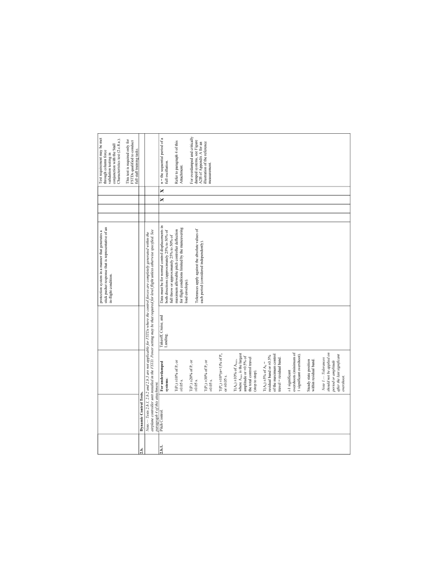
60
14 CFR Ch. I (1–1–24 Edition)
Pt. 60, App. A
VerDate Sep<11>2014
14:00 Mar 14, 2024
Jkt 262047
PO 00000
Frm 00070
Fmt 8010
Sfmt 8006
Q:\14\14V2.TXT
PC31
ER09DE22.024</GPH>
aworley on LAPBH6H6L3 with DISTILLER
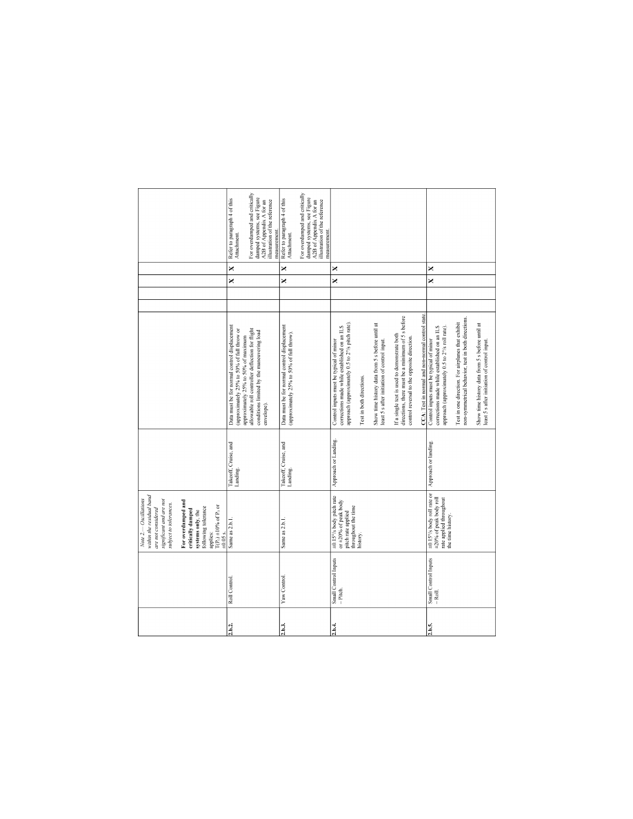
61
Federal Aviation Administration, DOT
Pt. 60, App. A
VerDate Sep<11>2014
14:00 Mar 14, 2024
Jkt 262047
PO 00000
Frm 00071
Fmt 8010
Sfmt 8006
Q:\14\14V2.TXT
PC31
ER09DE22.025</GPH>
aworley on LAPBH6H6L3 with DISTILLER
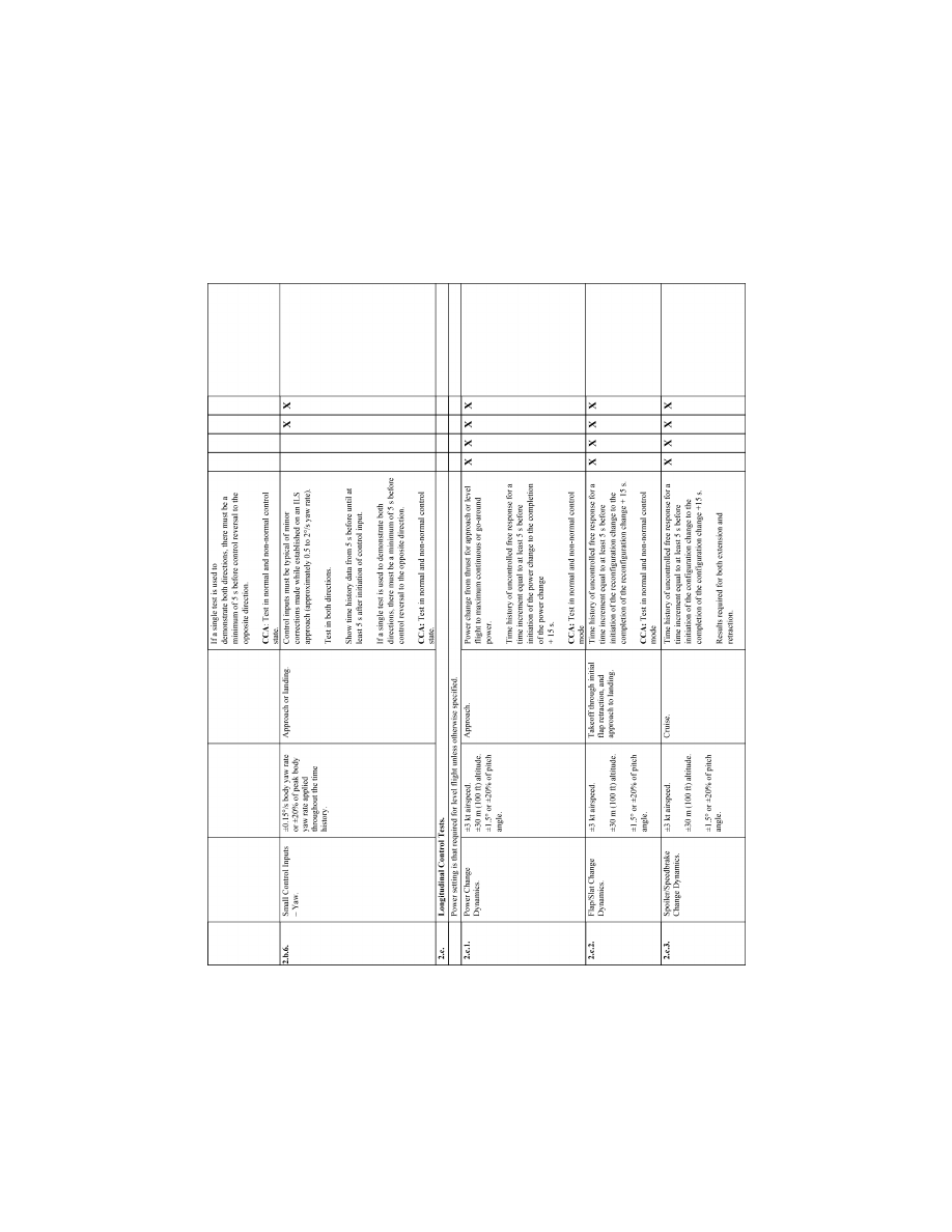
62
14 CFR Ch. I (1–1–24 Edition)
Pt. 60, App. A
VerDate Sep<11>2014
14:00 Mar 14, 2024
Jkt 262047
PO 00000
Frm 00072
Fmt 8010
Sfmt 8006
Q:\14\14V2.TXT
PC31
ER09DE22.026</GPH>
aworley on LAPBH6H6L3 with DISTILLER
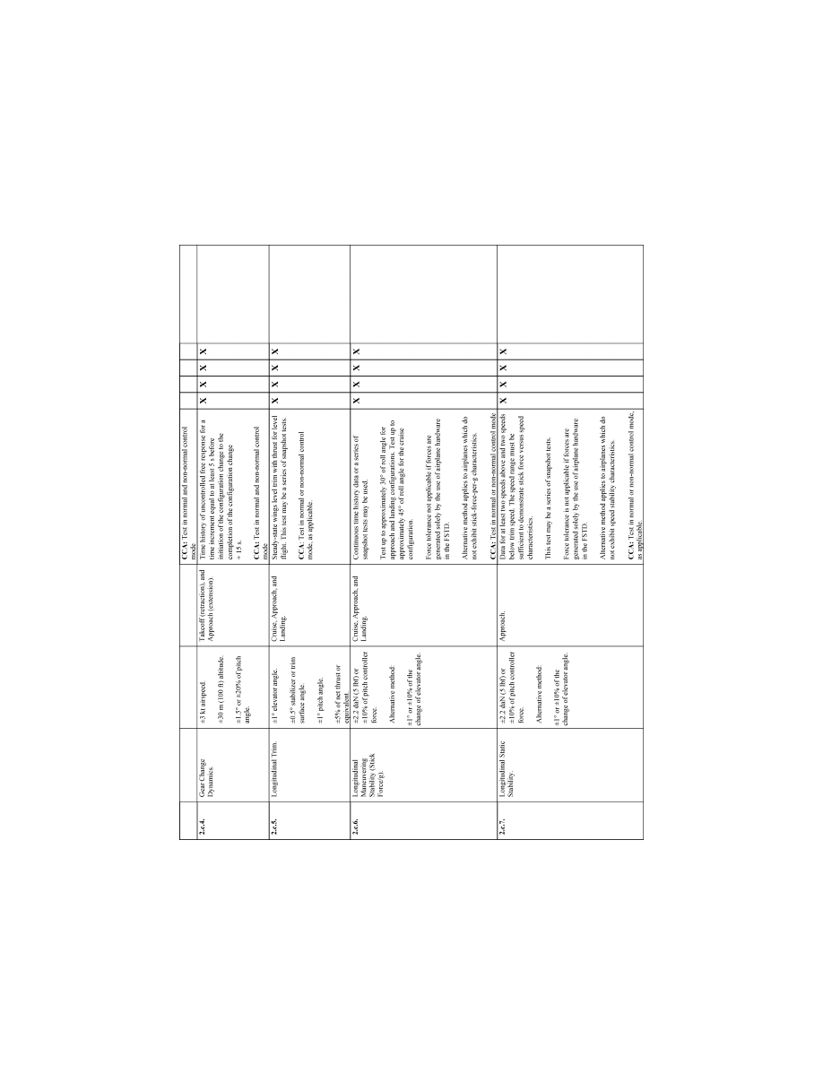
63
Federal Aviation Administration, DOT
Pt. 60, App. A
VerDate Sep<11>2014
14:00 Mar 14, 2024
Jkt 262047
PO 00000
Frm 00073
Fmt 8010
Sfmt 8006
Q:\14\14V2.TXT
PC31
ER09DE22.027</GPH>
aworley on LAPBH6H6L3 with DISTILLER
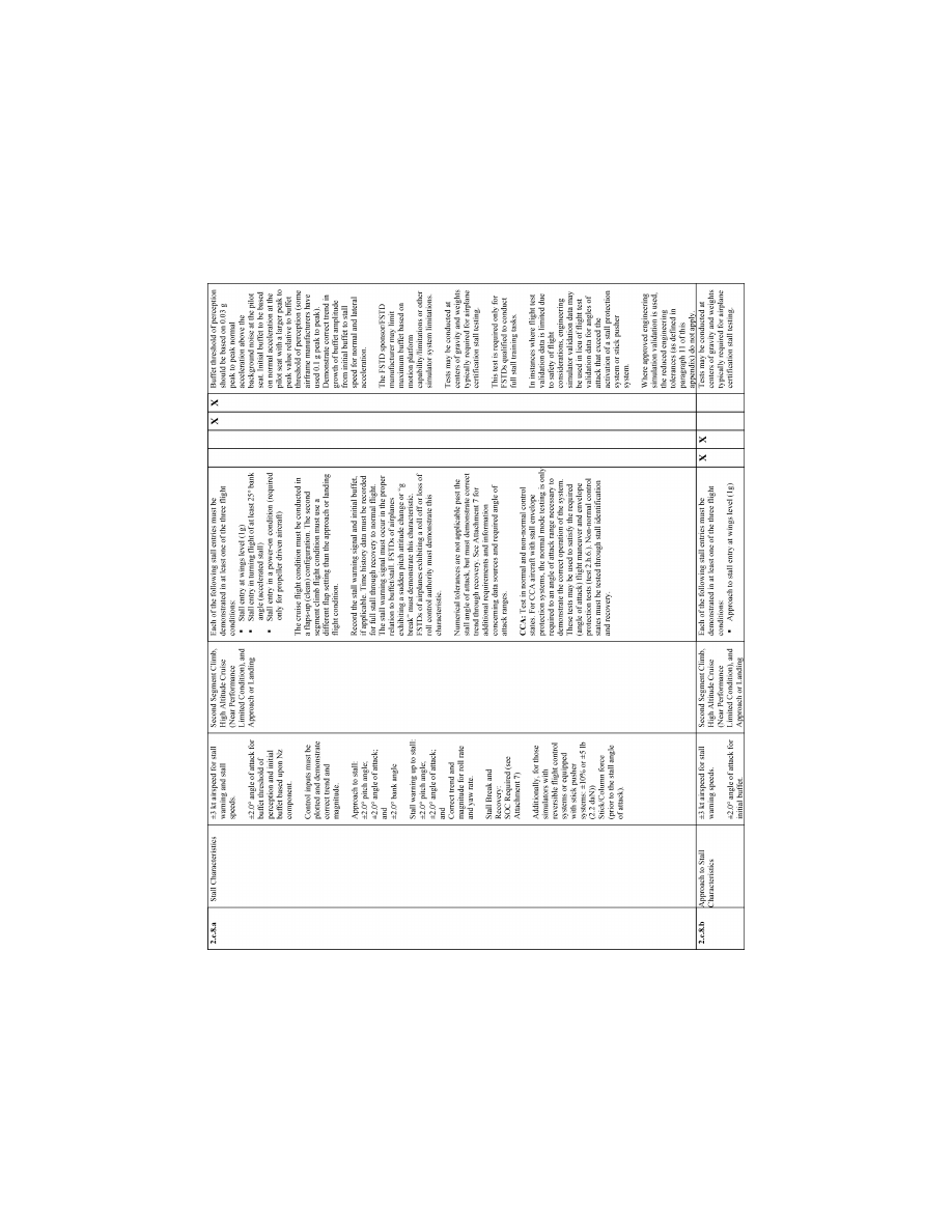
64
14 CFR Ch. I (1–1–24 Edition)
Pt. 60, App. A
VerDate Sep<11>2014
14:00 Mar 14, 2024
Jkt 262047
PO 00000
Frm 00074
Fmt 8010
Sfmt 8006
Q:\14\14V2.TXT
PC31
ER09DE22.028</GPH>
aworley on LAPBH6H6L3 with DISTILLER
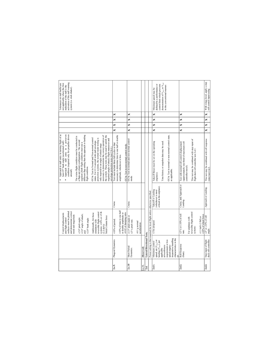
65
Federal Aviation Administration, DOT
Pt. 60, App. A
VerDate Sep<11>2014
14:00 Mar 14, 2024
Jkt 262047
PO 00000
Frm 00075
Fmt 8010
Sfmt 8006
Q:\14\14V2.TXT
PC31
ER09DE22.029</GPH>
aworley on LAPBH6H6L3 with DISTILLER
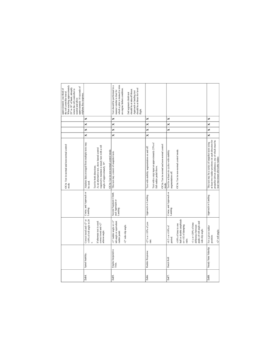
66
14 CFR Ch. I (1–1–24 Edition)
Pt. 60, App. A
VerDate Sep<11>2014
14:00 Mar 14, 2024
Jkt 262047
PO 00000
Frm 00076
Fmt 8010
Sfmt 8006
Q:\14\14V2.TXT
PC31
ER09DE22.030</GPH>
aworley on LAPBH6H6L3 with DISTILLER
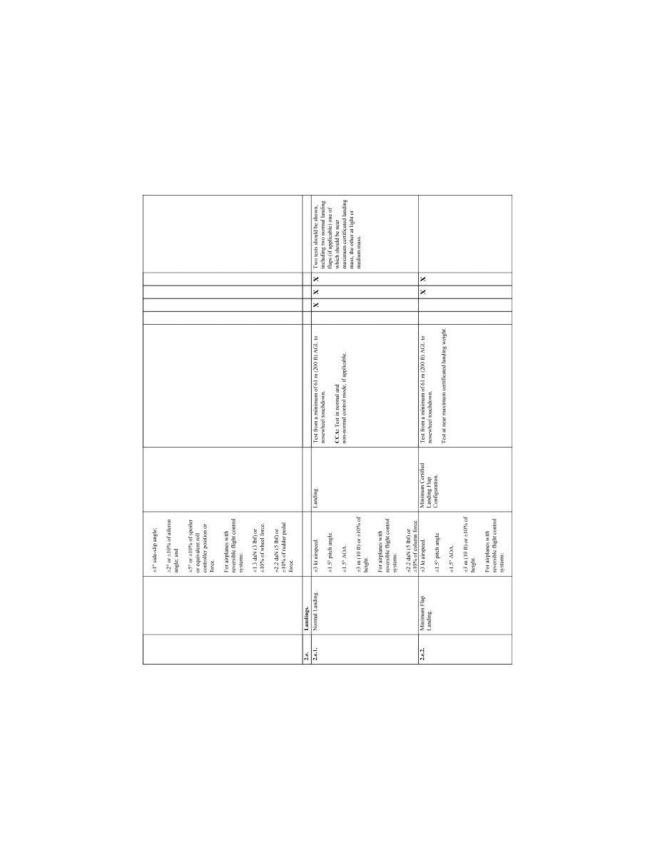
67
Federal Aviation Administration, DOT
Pt. 60, App. A
VerDate Sep<11>2014
14:00 Mar 14, 2024
Jkt 262047
PO 00000
Frm 00077
Fmt 8010
Sfmt 8006
Q:\14\14V2.TXT
PC31
ER09DE22.031</GPH>
aworley on LAPBH6H6L3 with DISTILLER
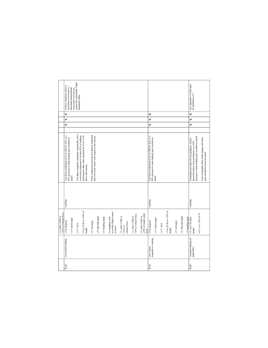
68
14 CFR Ch. I (1–1–24 Edition)
Pt. 60, App. A
VerDate Sep<11>2014
14:00 Mar 14, 2024
Jkt 262047
PO 00000
Frm 00078
Fmt 8010
Sfmt 8006
Q:\14\14V2.TXT
PC31
ER09DE22.032</GPH>
aworley on LAPBH6H6L3 with DISTILLER
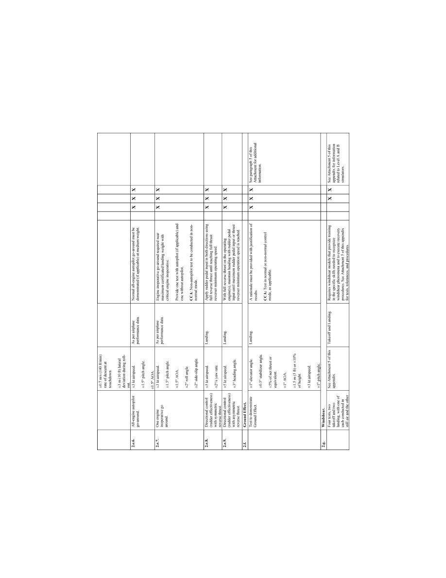
69
Federal Aviation Administration, DOT
Pt. 60, App. A
VerDate Sep<11>2014
14:00 Mar 14, 2024
Jkt 262047
PO 00000
Frm 00079
Fmt 8010
Sfmt 8006
Q:\14\14V2.TXT
PC31
ER09DE22.033</GPH>
aworley on LAPBH6H6L3 with DISTILLER
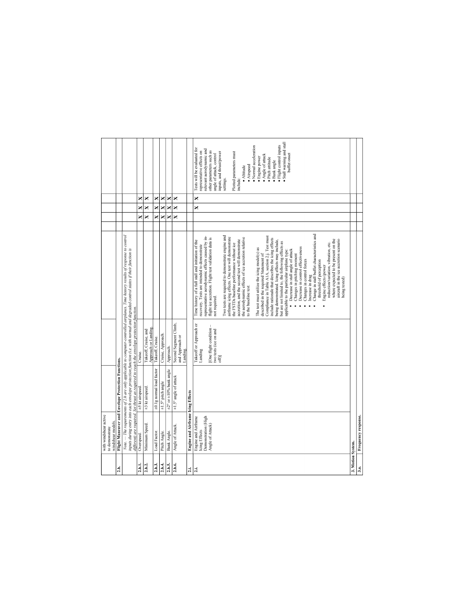
70
14 CFR Ch. I (1–1–24 Edition)
Pt. 60, App. A
VerDate Sep<11>2014
14:00 Mar 14, 2024
Jkt 262047
PO 00000
Frm 00080
Fmt 8010
Sfmt 8006
Q:\14\14V2.TXT
PC31
ER09DE22.034</GPH>
aworley on LAPBH6H6L3 with DISTILLER
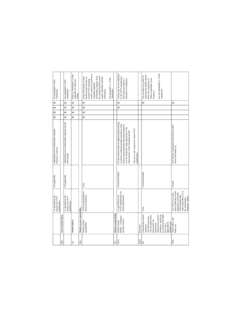
71
Federal Aviation Administration, DOT
Pt. 60, App. A
VerDate Sep<11>2014
14:00 Mar 14, 2024
Jkt 262047
PO 00000
Frm 00081
Fmt 8010
Sfmt 8006
Q:\14\14V2.TXT
PC31
ER09DE22.035</GPH>
aworley on LAPBH6H6L3 with DISTILLER
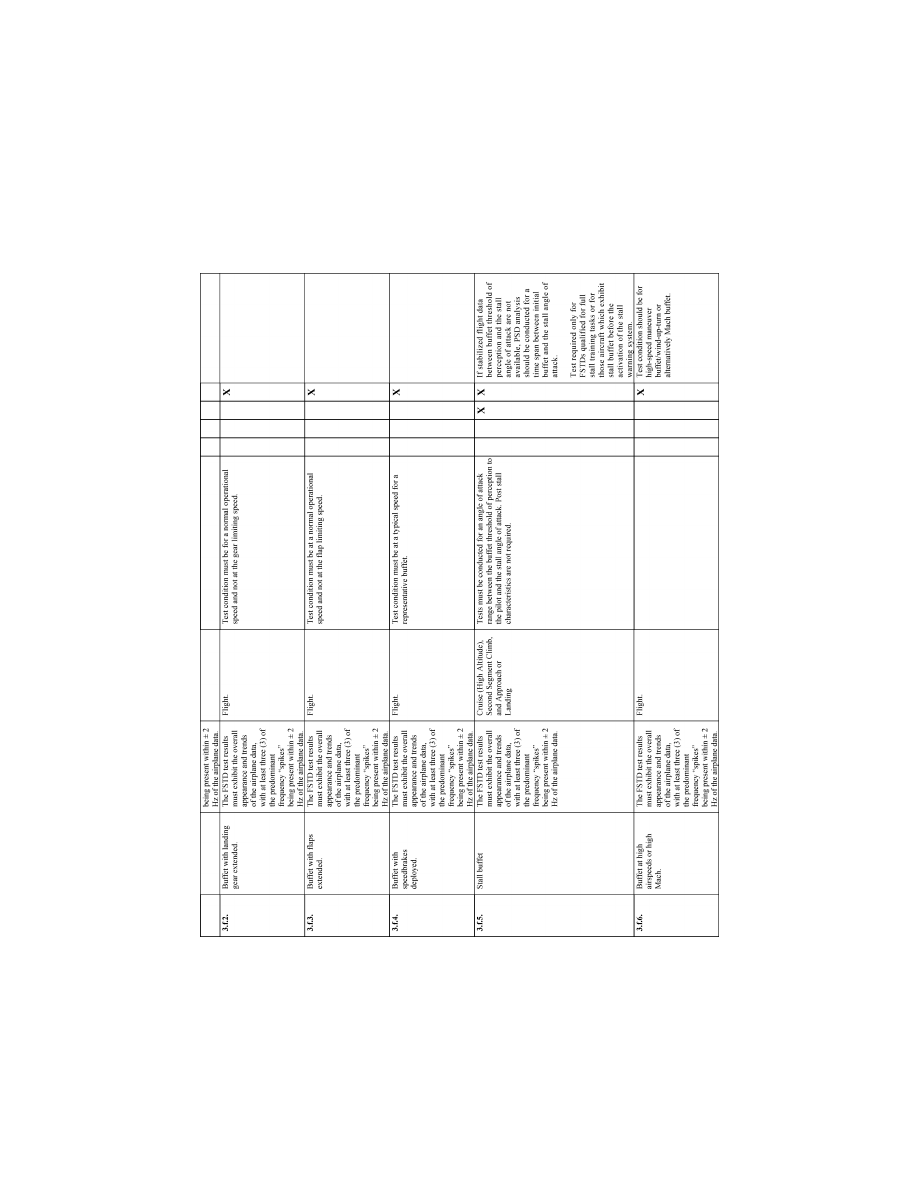
72
14 CFR Ch. I (1–1–24 Edition)
Pt. 60, App. A
VerDate Sep<11>2014
14:00 Mar 14, 2024
Jkt 262047
PO 00000
Frm 00082
Fmt 8010
Sfmt 8006
Q:\14\14V2.TXT
PC31
ER09DE22.036</GPH>
aworley on LAPBH6H6L3 with DISTILLER
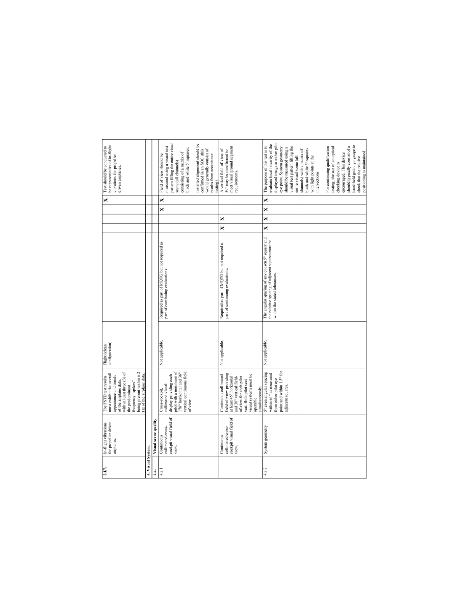
73
Federal Aviation Administration, DOT
Pt. 60, App. A
VerDate Sep<11>2014
14:00 Mar 14, 2024
Jkt 262047
PO 00000
Frm 00083
Fmt 8010
Sfmt 8006
Q:\14\14V2.TXT
PC31
ER09DE22.037</GPH>
aworley on LAPBH6H6L3 with DISTILLER
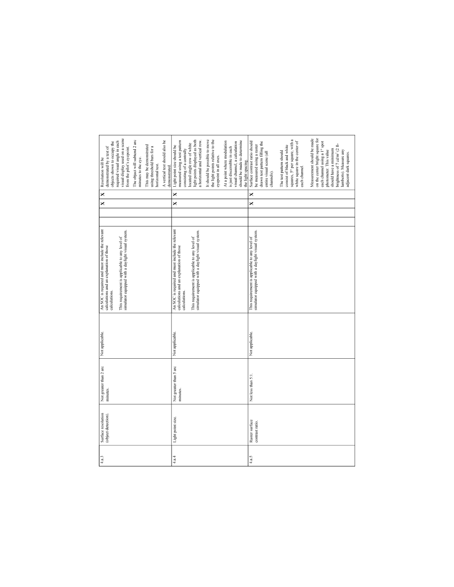
74
14 CFR Ch. I (1–1–24 Edition)
Pt. 60, App. A
VerDate Sep<11>2014
14:00 Mar 14, 2024
Jkt 262047
PO 00000
Frm 00084
Fmt 8010
Sfmt 8006
Q:\14\14V2.TXT
PC31
ER09DE22.038</GPH>
aworley on LAPBH6H6L3 with DISTILLER
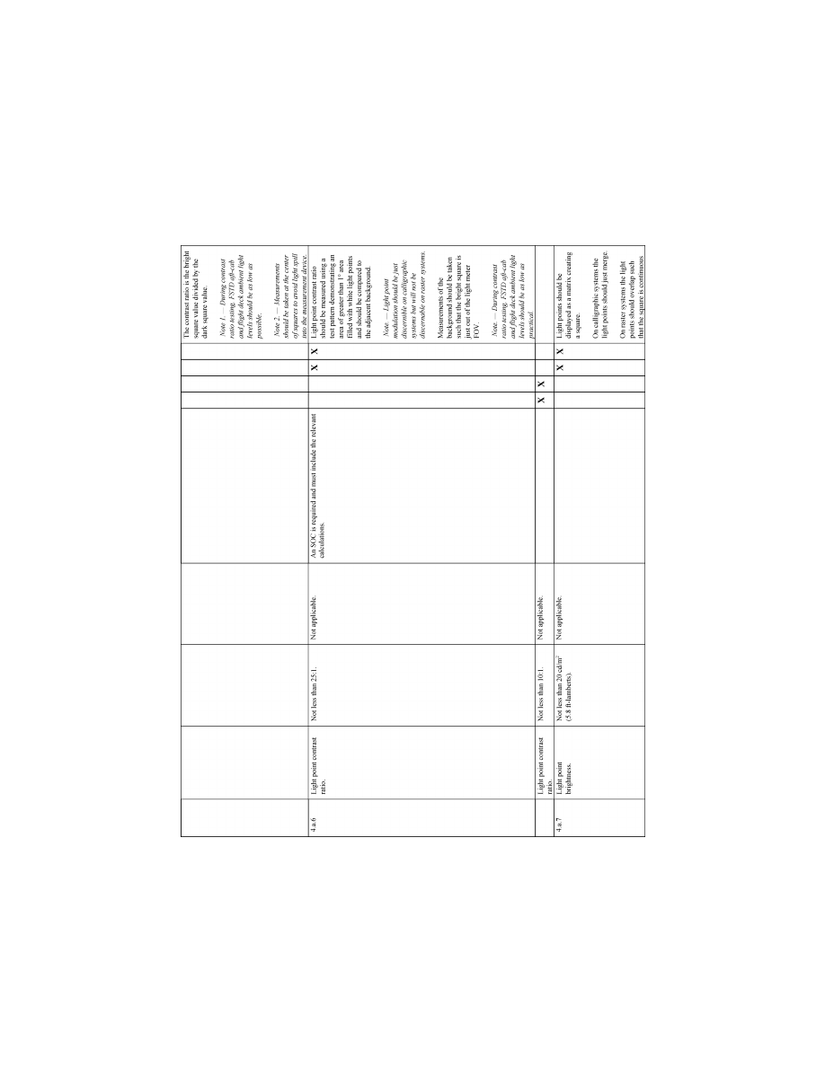
75
Federal Aviation Administration, DOT
Pt. 60, App. A
VerDate Sep<11>2014
14:00 Mar 14, 2024
Jkt 262047
PO 00000
Frm 00085
Fmt 8010
Sfmt 8006
Q:\14\14V2.TXT
PC31
ER09DE22.039</GPH>
aworley on LAPBH6H6L3 with DISTILLER
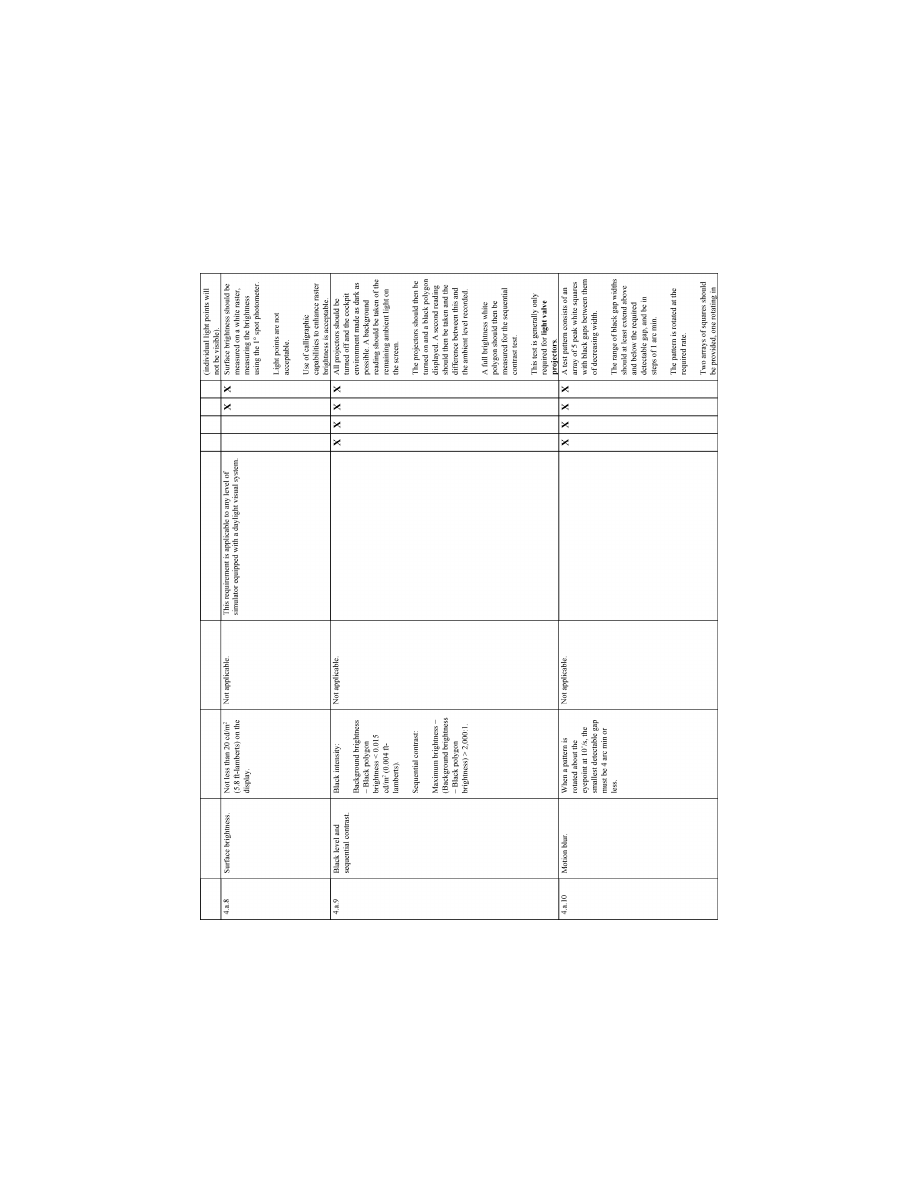
76
14 CFR Ch. I (1–1–24 Edition)
Pt. 60, App. A
VerDate Sep<11>2014
14:00 Mar 14, 2024
Jkt 262047
PO 00000
Frm 00086
Fmt 8010
Sfmt 8006
Q:\14\14V2.TXT
PC31
ER09DE22.040</GPH>
aworley on LAPBH6H6L3 with DISTILLER
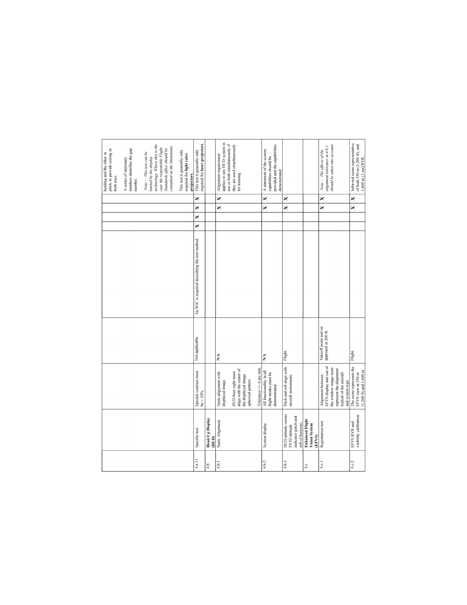
77
Federal Aviation Administration, DOT
Pt. 60, App. A
VerDate Sep<11>2014
14:00 Mar 14, 2024
Jkt 262047
PO 00000
Frm 00087
Fmt 8010
Sfmt 8006
Q:\14\14V2.TXT
PC31
ER09DE22.041</GPH>
aworley on LAPBH6H6L3 with DISTILLER
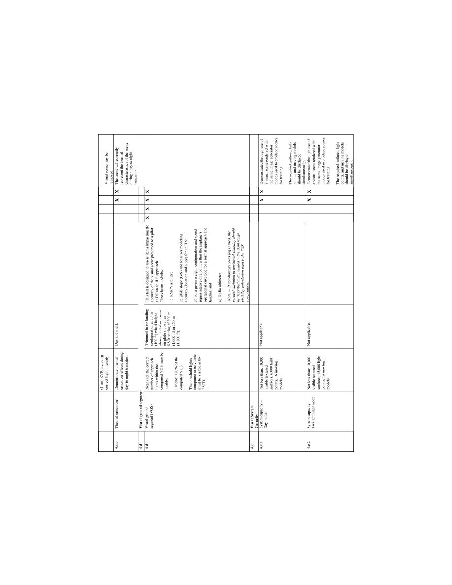
78
14 CFR Ch. I (1–1–24 Edition)
Pt. 60, App. A
VerDate Sep<11>2014
14:00 Mar 14, 2024
Jkt 262047
PO 00000
Frm 00088
Fmt 8010
Sfmt 8006
Q:\14\14V2.TXT
PC31
ER09DE22.042</GPH>
aworley on LAPBH6H6L3 with DISTILLER
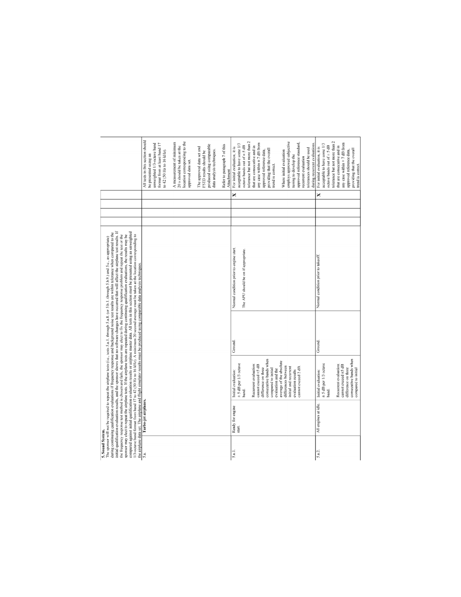
79
Federal Aviation Administration, DOT
Pt. 60, App. A
VerDate Sep<11>2014
14:00 Mar 14, 2024
Jkt 262047
PO 00000
Frm 00089
Fmt 8010
Sfmt 8006
Q:\14\14V2.TXT
PC31
ER09DE22.043</GPH>
aworley on LAPBH6H6L3 with DISTILLER
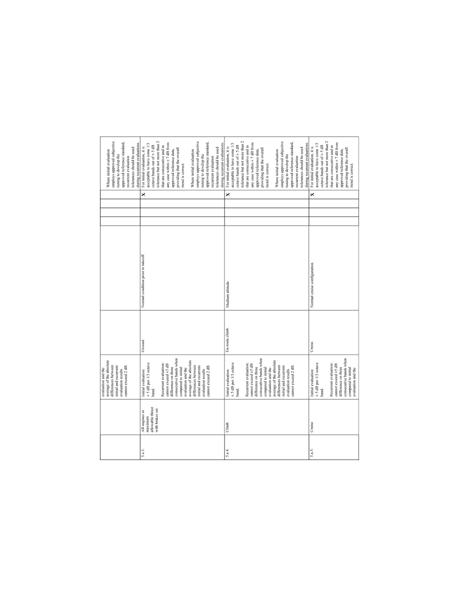
80
14 CFR Ch. I (1–1–24 Edition)
Pt. 60, App. A
VerDate Sep<11>2014
14:00 Mar 14, 2024
Jkt 262047
PO 00000
Frm 00090
Fmt 8010
Sfmt 8006
Q:\14\14V2.TXT
PC31
ER09DE22.044</GPH>
aworley on LAPBH6H6L3 with DISTILLER
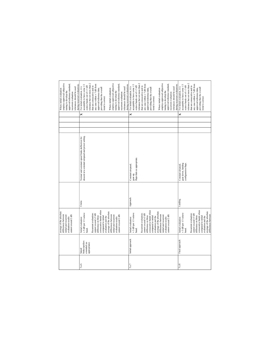
81
Federal Aviation Administration, DOT
Pt. 60, App. A
VerDate Sep<11>2014
14:00 Mar 14, 2024
Jkt 262047
PO 00000
Frm 00091
Fmt 8010
Sfmt 8006
Q:\14\14V2.TXT
PC31
ER09DE22.045</GPH>
aworley on LAPBH6H6L3 with DISTILLER
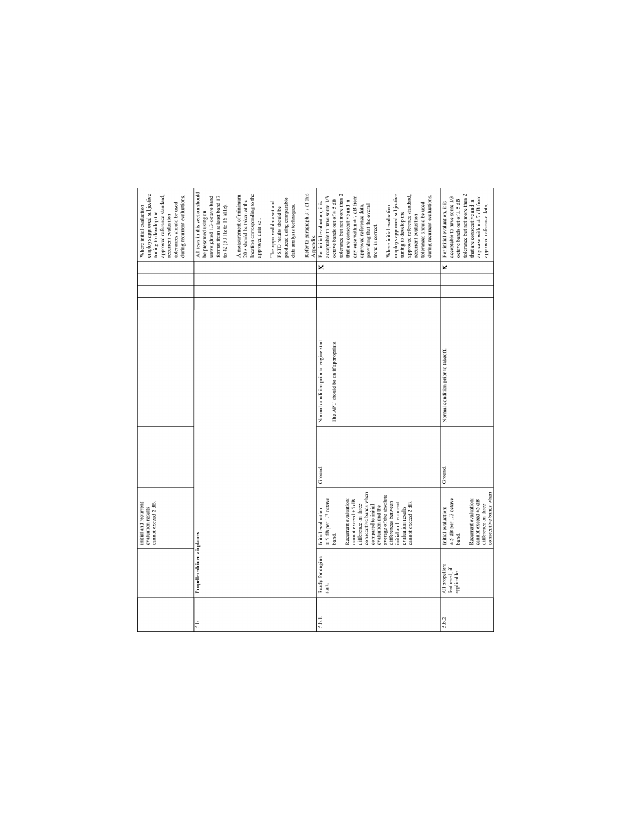
82
14 CFR Ch. I (1–1–24 Edition)
Pt. 60, App. A
VerDate Sep<11>2014
14:00 Mar 14, 2024
Jkt 262047
PO 00000
Frm 00092
Fmt 8010
Sfmt 8006
Q:\14\14V2.TXT
PC31
ER09DE22.046</GPH>
aworley on LAPBH6H6L3 with DISTILLER
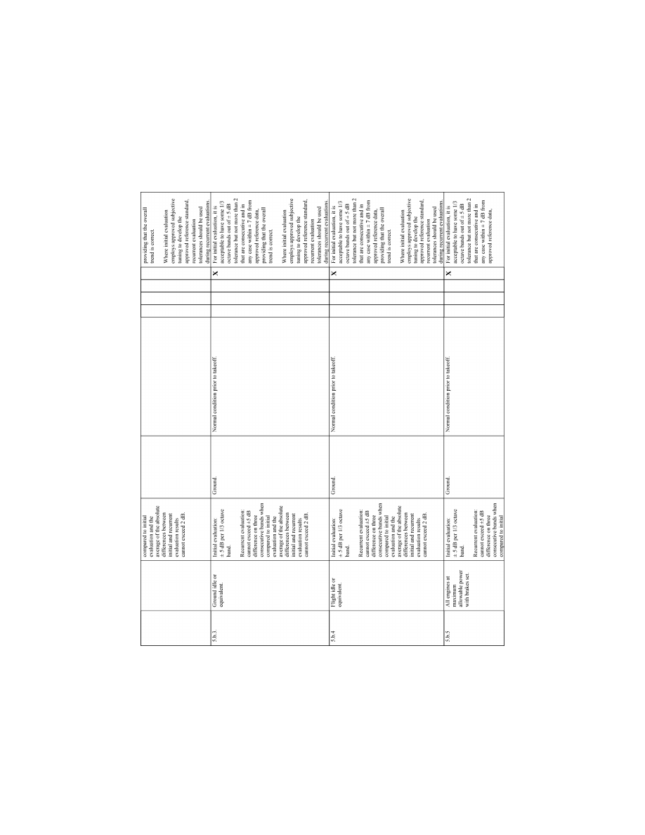
83
Federal Aviation Administration, DOT
Pt. 60, App. A
VerDate Sep<11>2014
14:00 Mar 14, 2024
Jkt 262047
PO 00000
Frm 00093
Fmt 8010
Sfmt 8006
Q:\14\14V2.TXT
PC31
ER09DE22.047</GPH>
aworley on LAPBH6H6L3 with DISTILLER
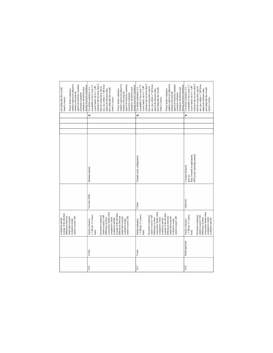
84
14 CFR Ch. I (1–1–24 Edition)
Pt. 60, App. A
VerDate Sep<11>2014
14:00 Mar 14, 2024
Jkt 262047
PO 00000
Frm 00094
Fmt 8010
Sfmt 8006
Q:\14\14V2.TXT
PC31
ER09DE22.048</GPH>
aworley on LAPBH6H6L3 with DISTILLER
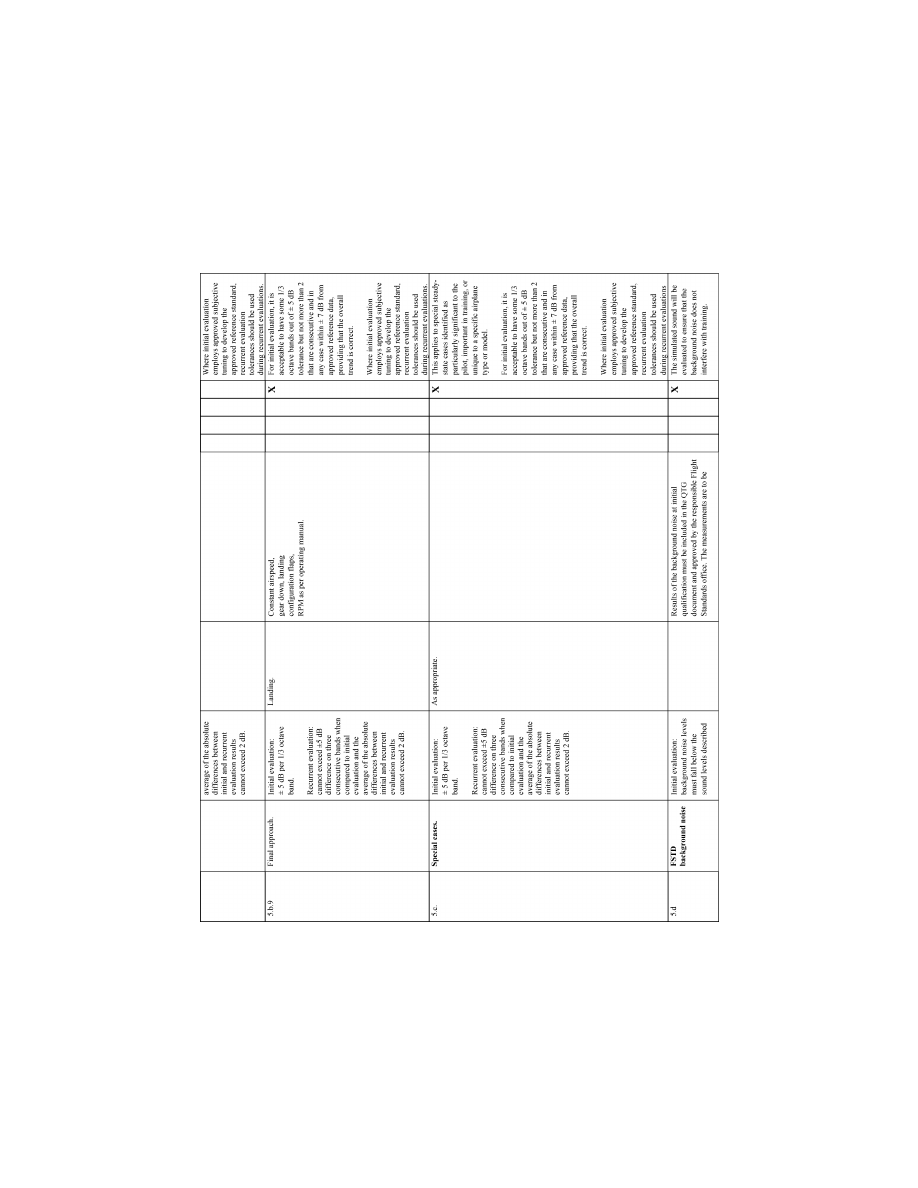
85
Federal Aviation Administration, DOT
Pt. 60, App. A
VerDate Sep<11>2014
14:00 Mar 14, 2024
Jkt 262047
PO 00000
Frm 00095
Fmt 8010
Sfmt 8006
Q:\14\14V2.TXT
PC31
ER09DE22.049</GPH>
aworley on LAPBH6H6L3 with DISTILLER
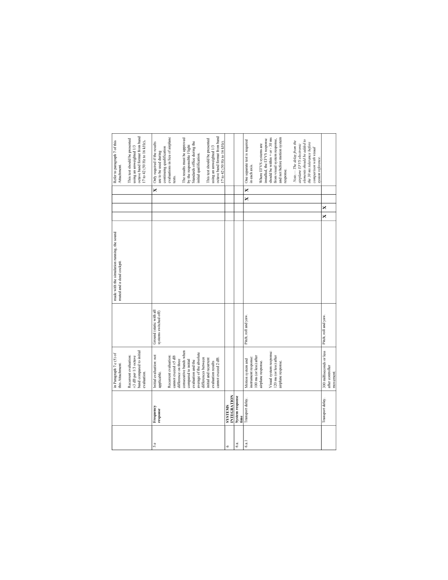
86
14 CFR Ch. I (1–1–24 Edition)
Pt. 60, App. A
llllllllllllllllllllllll
B
EGIN
I
NFORMATION
3. G
ENERAL
a. If relevant winds are present in the ob-
jective data, the wind vector should be clear-
ly noted as part of the data presentation, ex-
pressed in conventional terminology, and re-
lated to the runway being used for test near
the ground.
b. The reader is encouraged to review the
Airplane Flight Simulator Evaluation Hand-
book, Volumes I and II, published by the
Royal Aeronautical Society, London, UK,
and AC 25–7, as amended, Flight Test Guide
for Certification of Transport Category Air-
planes, and AC 23–8, as amended, Flight Test
VerDate Sep<11>2014
14:00 Mar 14, 2024
Jkt 262047
PO 00000
Frm 00096
Fmt 8010
Sfmt 8002
Q:\14\14V2.TXT
PC31
ER09DE22.050</GPH>
aworley on LAPBH6H6L3 with DISTILLER

87
Federal Aviation Administration, DOT
Pt. 60, App. A
Guide for Certification of Part 23 Airplanes,
for references and examples regarding flight
testing requirements and techniques.
4. C
ONTROL
D
YNAMICS
a. General. The characteristics of an air-
plane flight control system have a major ef-
fect on handling qualities. A significant con-
sideration in pilot acceptability of an air-
plane is the ‘‘feel’’ provided through the
flight controls. Considerable effort is ex-
pended on airplane feel system design so that
pilots will be comfortable and will consider
the airplane desirable to fly. In order for an
FFS to be representative, it should ‘‘feel’’
like the airplane being simulated. Compli-
ance with this requirement is determined by
comparing a recording of the control feel dy-
namics of the FFS to actual airplane meas-
urements in the takeoff, cruise and landing
configurations.
(1) Recordings such as free response to an
impulse or step function are classically used
to estimate the dynamic properties of
electromechanical systems. In any case, it is
only possible to estimate the dynamic prop-
erties as a result of being able to estimate
true inputs and responses. Therefore, it is
imperative that the best possible data be col-
lected since close matching of the FFS con-
trol loading system to the airplane system is
essential. The required dynamic control
tests are described in Table A2A of this at-
tachment.
(2) For initial and upgrade evaluations, the
QPS requires that control dynamics charac-
teristics be measured and recorded directly
from the flight controls (Handling Quali-
ties—Table A2A). This procedure is usually
accomplished by measuring the free response
of the controls using a step or impulse input
to excite the system. The procedure should
be accomplished in the takeoff, cruise and
landing flight conditions and configurations.
(3) For airplanes with irreversible control
systems, measurements may be obtained on
the ground if proper pitot-static inputs are
provided to represent airspeeds typical of
those encountered in flight. Likewise, it may
be shown that for some airplanes, takeoff,
cruise, and landing configurations have like
effects. Thus, one may suffice for another. In
either case, engineering validation or air-
plane manufacturer rationale should be sub-
mitted as justification for ground tests or for
eliminating a configuration. For FFSs re-
quiring static and dynamic tests at the con-
trols, special test fixtures will not be re-
quired during initial and upgrade evalua-
tions if the QTG shows both test fixture re-
sults and the results of an alternate ap-
proach (e.g., computer plots that were pro-
duced concurrently and show satisfactory
agreement). Repeat of the alternate method
during the initial evaluation satisfies this
test requirement.
b. Control Dynamics Evaluation. The dy-
namic properties of control systems are
often stated in terms of frequency, damping
and a number of other classical measure-
ments. In order to establish a consistent
means of validating test results for FFS con-
trol loading, criteria are needed that will
clearly define the measurement interpreta-
tion and the applied tolerances. Criteria are
needed for underdamped, critically damped
and overdamped systems. In the case of an
underdamped system with very light damp-
ing, the system may be quantified in terms
of frequency and damping. In critically
damped or overdamped systems, the fre-
quency and damping are not readily meas-
ured from a response time history. There-
fore, the following suggested measurements
may be used:
(1) For Level C and D simulators. Tests to
verify that control feel dynamics represent
the airplane should show that the dynamic
damping cycles (free response of the con-
trols) match those of the airplane within
specified tolerances. The Flight Standards
Service recognizes that several different
testing methods may be used to verify the
control feel dynamic response. The respon-
sible Flight Standards office will consider
the merits of testing methods based on reli-
ability and consistency. One acceptable
method of evaluating the response and the
tolerance to be applied is described below for
the underdamped and critically damped
cases. A sponsor using this method to com-
ply with the QPS requirements should per-
form the tests as follows:
(a) Underdamped response. Two measure-
ments are required for the period, the time
to first zero crossing (in case a rate limit is
present) and the subsequent frequency of os-
cillation. It is necessary to measure cycles
on an individual basis in case there are non-
uniform periods in the response. Each period
will be independently compared to the re-
spective period of the airplane control sys-
tem and, consequently, will enjoy the full
tolerance specified for that period. The
damping tolerance will be applied to over-
shoots on an individual basis. Care should be
taken when applying the tolerance to small
overshoots since the significance of such
overshoots becomes questionable. Only those
overshoots larger than 5 per cent of the total
initial displacement should be considered.
The residual band, labeled T(A
d
) on Figure
A2A is
±
5 percent of the initial displacement
amplitude A
d
from the steady state value of
the oscillation. Only oscillations outside the
residual band are considered significant.
When comparing FFS data to airplane data,
the process should begin by overlaying or
aligning the FFS and airplane steady state
values and then comparing amplitudes of os-
cillation peaks, the time of the first zero
crossing and individual periods of oscilla-
tion. The FFS should show the same number
VerDate Sep<11>2014
14:00 Mar 14, 2024
Jkt 262047
PO 00000
Frm 00097
Fmt 8010
Sfmt 8002
Q:\14\14V2.TXT
PC31
aworley on LAPBH6H6L3 with DISTILLER

88
14 CFR Ch. I (1–1–24 Edition)
Pt. 60, App. A
of significant overshoots to within one when
compared against the airplane data. The pro-
cedure for evaluating the response is illus-
trated in Figure A2A.
(b) Critically damped and overdamped re-
sponse. Due to the nature of critically
damped and overdamped responses (no over-
shoots), the time to reach 90 percent of the
steady state (neutral point) value should be
the same as the airplane within
±
10 percent.
Figure A2B illustrates the procedure.
(c) Special considerations. Control systems
that exhibit characteristics other than clas-
sical overdamped or underdamped responses
should meet specified tolerances. In addi-
tion, special consideration should be given to
ensure that significant trends are main-
tained.
(2) Tolerances.
(a) The following table summarizes the tol-
erances, T, for underdamped systems, and
‘‘n’’ is the sequential period of a full cycle of
oscillation. See Figure A2A of this attach-
ment for an illustration of the referenced
measurements.
T(P
0
) ..........
±
10% of P
0
.
T(P
1
) ..........
±
20% of P
1
.
T(P
2
) ..........
±
30% of P
2
.
T(P
n
) ..........
±
10(n + 1)% of P
n
.
T(A
n
) ..........
±
10% of A
1
.
T(A
d
) ..........
±
5% of A
d
= residual
band.
Significant overshoots, First overshoot
and
±
1 subsequent overshoots.
(b) The following tolerance applies to criti-
cally damped and overdamped systems only.
See Figure A2B for an illustration of the ref-
erence measurements:
T(P
0
) ..........
±
10% of P
0
E
ND
I
NFORMATION
llllllllllllllllllllllll
B
EGIN
QPS R
EQUIREMENT
c. Alternative method for control dynam-
ics evaluation.
(1) An alternative means for validating
control dynamics for aircraft with hydrau-
lically powered flight controls and artificial
feel systems is by the measurement of con-
trol force and rate of movement. For each
axis of pitch, roll, and yaw, the control must
be forced to its maximum extreme position
for the following distinct rates. These tests
are conducted under normal flight and
ground conditions.
(a) Static test—Slowly move the control so
that a full sweep is achieved within 95 to 105
seconds. A full sweep is defined as movement
of the controller from neutral to the stop,
usually aft or right stop, then to the oppo-
site stop, then to the neutral position.
(b) Slow dynamic test—Achieve a full
sweep within 8–12 seconds.
(c) Fast dynamic test—Achieve a full
sweep within 3–5 seconds.
N
OTE
: Dynamic sweeps may be limited to
forces not exceeding 100 lbs. (44.5 daN).
(d) Tolerances
(i) Static test; see Table A2A, FFS Objec-
tive Tests, Entries 2.a.1., 2.a.2., and 2.a.3.
(ii) Dynamic test—
±
2 lbs (0.9 daN) or
±
10%
on dynamic increment above static test.
E
ND
QPS R
EQUIREMENT
llllllllllllllllllllllll
B
EGIN
I
NFORMATION
d. The FAA is open to alternative means
such as the one described above. The alter-
natives should be justified and appropriate
to the application. For example, the method
described here may not apply to all manufac-
turers’ systems and certainly not to aircraft
with reversible control systems. Each case is
considered on its own merit on an ad hoc
basis. If the FAA finds that alternative
methods do not result in satisfactory per-
formance, more conventionally accepted
methods will have to be used.
VerDate Sep<11>2014
14:00 Mar 14, 2024
Jkt 262047
PO 00000
Frm 00098
Fmt 8010
Sfmt 8002
Q:\14\14V2.TXT
PC31
aworley on LAPBH6H6L3 with DISTILLER
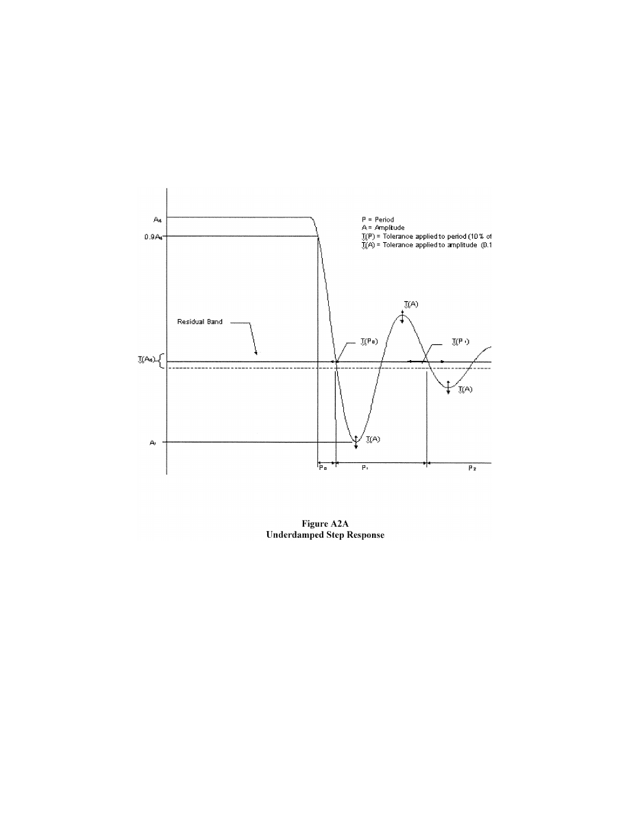
89
Federal Aviation Administration, DOT
Pt. 60, App. A
VerDate Sep<11>2014
14:00 Mar 14, 2024
Jkt 262047
PO 00000
Frm 00099
Fmt 8010
Sfmt 8006
Q:\14\14V2.TXT
PC31
ER09MY08.000</GPH>
aworley on LAPBH6H6L3 with DISTILLER
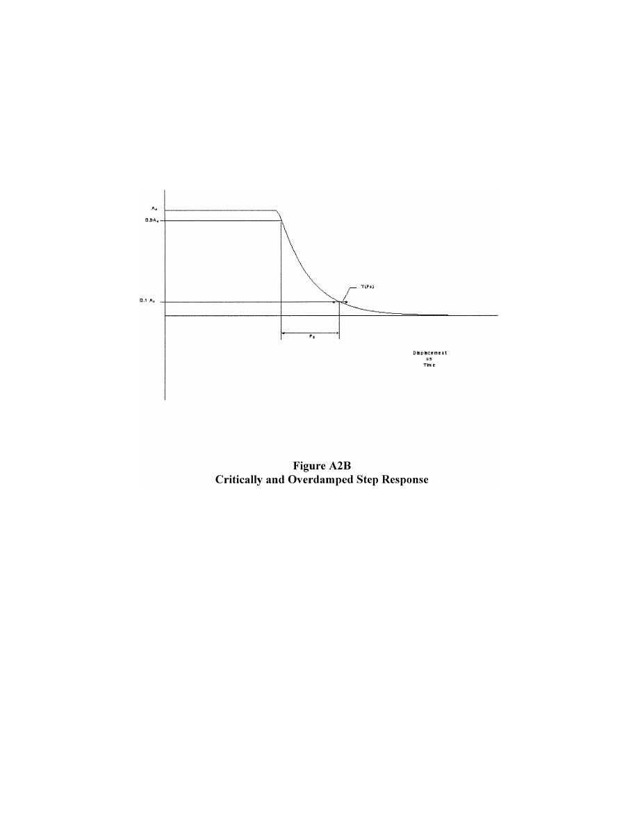
90
14 CFR Ch. I (1–1–24 Edition)
Pt. 60, App. A
5. G
ROUND
E
FFECT
a. For an FFS to be used for take-off and
landing (not applicable to Level A simula-
tors in that the landing maneuver may not
be credited in a Level A simulator) it should
reproduce the aerodynamic changes that
occur in ground effect. The parameters cho-
sen for FFS validation should indicate these
changes.
(1) A dedicated test should be provided that
will validate the aerodynamic ground effect
characteristics.
(2) The organization performing the flight
tests may select appropriate test methods
and procedures to validate ground effect.
However, the flight tests should be per-
formed with enough duration near the
ground to sufficiently validate the ground-
effect model.
b. The responsible Flight Standards office
will consider the merits of testing methods
based on reliability and consistency. Accept-
able methods of validating ground effect are
described below. If other methods are pro-
posed, rationale should be provided to con-
clude that the tests performed validate the
ground-effect model. A sponsor using the
methods described below to comply with the
QPS requirements should perform the tests
as follows:
(1) Level fly-bys. The level fly-bys should
be conducted at a minimum of three alti-
tudes within the ground effect, including one
at no more than 10% of the wingspan above
the ground, one each at approximately 30%
and 50% of the wingspan where height refers
to main gear tire above the ground. In addi-
tion, one level-flight trim condition should
be conducted out of ground effect (e.g., at
150% of wingspan).
(2) Shallow approach landing. The shallow
approach landing should be performed at a
glide slope of approximately one degree with
negligible pilot activity until flare.
c. The lateral-directional characteristics
are also altered by ground effect. For exam-
ple, because of changes in lift, roll damping
is affected. The change in roll damping will
affect other dynamic modes usually evalu-
ated for FFS validation. In fact, Dutch roll
dynamics, spiral stability, and roll-rate for a
given lateral control input are altered by
ground effect. Steady heading sideslips will
also be affected. These effects should be ac-
counted for in the FFS modeling. Several
VerDate Sep<11>2014
14:00 Mar 14, 2024
Jkt 262047
PO 00000
Frm 00100
Fmt 8010
Sfmt 8002
Q:\14\14V2.TXT
PC31
ER09MY08.001</GPH>
aworley on LAPBH6H6L3 with DISTILLER

91
Federal Aviation Administration, DOT
Pt. 60, App. A
tests such as crosswind landing, one engine
inoperative landing, and engine failure on
take-off serve to validate lateral-directional
ground effect since portions of these tests
are accomplished as the aircraft is descend-
ing through heights above the runway at
which ground effect is an important factor.
6. M
OTION
S
YSTEM
a. General.
(1) Pilots use continuous information sig-
nals to regulate the state of the airplane. In
concert with the instruments and outside-
world visual information, whole-body motion
feedback is essential in assisting the pilot to
control the airplane dynamics, particularly
in the presence of external disturbances. The
motion system should meet basic objective
performance criteria, and should be subjec-
tively tuned at the pilot’s seat position to
represent the linear and angular accelera-
tions of the airplane during a prescribed
minimum set of maneuvers and conditions.
The response of the motion cueing system
should also be repeatable.
(2) The Motion System tests in Section 3 of
Table A2A are intended to qualify the FFS
motion cueing system from a mechanical
performance standpoint. Additionally, the
list of motion effects provides a representa-
tive sample of dynamic conditions that
should be present in the flight simulator. An
additional list of representative, training-
critical maneuvers, selected from Section 1
(Performance tests), and Section 2 (Handling
Qualities tests), in Table A2A, that should be
recorded during initial qualification (but
without tolerance) to indicate the flight sim-
ulator motion cueing performance signature
have been identified (reference Section 3.e).
These tests are intended to help improve the
overall standard of FFS motion cueing.
b. Motion System Checks. The intent of
test 3a, Frequency Response, and test 3b,
Turn-Around Check, as described in the
Table of Objective Tests, are to demonstrate
the performance of the motion system hard-
ware, and to check the integrity of the mo-
tion set-up with regard to calibration and
wear. These tests are independent of the mo-
tion cueing software and should be consid-
ered robotic tests.
c. Motion System Repeatability. The in-
tent of this test is to ensure that the motion
system software and motion system hard-
ware have not degraded or changed over
time. This diagnostic test should be com-
pleted during continuing qualification
checks in lieu of the robotic tests. This will
allow an improved ability to determine
changes in the software or determine deg-
radation in the hardware. The following in-
formation delineates the methodology that
should be used for this test.
(1) Input: The inputs should be such that
rotational accelerations, rotational rates,
and linear accelerations are inserted before
the transfer from airplane center of gravity
to pilot reference point with a minimum am-
plitude of 5 deg/sec/sec, 10 deg/sec and 0.3 g,
respectively, to provide adequate analysis of
the output.
(2) Recommended output:
(a) Actual platform linear accelerations;
the output will comprise accelerations due
to both the linear and rotational motion ac-
celeration;
(b) Motion actuators position.
d. Objective Motion Cueing Test—Fre-
quency Domain
(1) Background. This test quantifies the re-
sponse of the motion cueing system from the
output of the flight model to the motion
platform response. Other motion tests, such
as the motion system frequency response,
concentrate on the mechanical performance
of the motion system hardware alone. The
intent of this test is to provide quantitative
frequency response records of the entire mo-
tion system for specified degree-of-freedom
transfer relationships over a range of fre-
quencies. This range should be representa-
tive of the manual control range for that
particular aircraft type and the simulator as
set up during qualification. The measure-
ments of this test should include the com-
bined influence of the motion cueing algo-
rithm, the motion platform dynamics, and
the transport delay associated with the mo-
tion cueing and control system implementa-
tion. Specified frequency responses describ-
ing the ability of the FSTD to reproduce air-
craft translations and rotations, as well as
the cross-coupling relations, are required as
part of these measurements. When simu-
lating forward aircraft acceleration, the sim-
ulator is accelerated momentarily in the for-
ward direction to provide the onset cueing.
This is considered the direct transfer rela-
tion. The simulator is simultaneously tilted
nose-up due to the low-pass filter in order to
generate a sustained specific force. The tilt
associated with the generation of the sus-
tained specific force, and the angular rates
and angular accelerations associated with
the initiation of the sustained specific force,
are considered cross-coupling relations. The
specific force is required for the perception
of the aircraft sustained specific force, while
the angular rates and accelerations do not
occur in the aircraft and should be mini-
mized.
(2) Frequency response test. This test re-
quires the frequency response to be measured
for the motion cueing system. Reference si-
nusoidal signals are inserted at the pilot ref-
erence position prior to the motion cueing
computations. The response of the motion
platform in the corresponding degree-of-free-
dom (the direct transfer relations), as well as
the motions resulting from cross-coupling
(the cross-coupling relations), are recorded.
These are the tests that are important to
VerDate Sep<11>2014
14:00 Mar 14, 2024
Jkt 262047
PO 00000
Frm 00101
Fmt 8010
Sfmt 8002
Q:\14\14V2.TXT
PC31
aworley on LAPBH6H6L3 with DISTILLER

92
14 CFR Ch. I (1–1–24 Edition)
Pt. 60, App. A
pilot motion cueing and are general tests ap-
plicable to all types of airplanes.
(3) This test is only required to be run once
for the initial qualification of the FSTD and
will not be required for continuing qualifica-
tion purposes. The FAA will accept test re-
sults provided by the FSTD manufacturer as
part of a Statement of Compliance con-
firming that the objective motion cueing
tests were used to assist in the tuning of the
FSTD’s motion cueing algorithms.
e. Motion Vibrations.
(1) Presentation of results. The char-
acteristic motion vibrations may be used to
verify that the flight simulator can repro-
duce the frequency content of the airplane
when flown in specific conditions. The test
results should be presented as a Power Spec-
tral Density (PSD) plot with frequencies on
the horizontal axis and amplitude on the
vertical axis. The airplane data and flight
simulator data should be presented in the
same format with the same scaling. The al-
gorithms used for generating the flight simu-
lator data should be the same as those used
for the airplane data. If they are not the
same then the algorithms used for the flight
simulator data should be proven to be suffi-
ciently comparable. As a minimum, the re-
sults along the dominant axes should be pre-
sented and a rationale for not presenting the
other axes should be provided.
(2) Interpretation of results. The overall
trend of the PSD plot should be considered
while focusing on the dominant frequencies.
Less emphasis should be placed on the dif-
ferences at the high frequency and low am-
plitude portions of the PSD plot. During the
analysis, certain structural components of
the flight simulator have resonant fre-
quencies that are filtered and may not ap-
pear in the PSD plot. If filtering is required,
the notch filter bandwidth should be limited
to 1 Hz to ensure that the buffet feel is not
adversely affected. In addition, a rationale
should be provided to explain that the char-
acteristic motion vibration is not being ad-
versely affected by the filtering. The ampli-
tude should match airplane data as described
below. However, if the PSD plot was altered
for subjective reasons, a rationale should be
provided to justify the change. If the plot is
on a logarithmic scale, it may be difficult to
interpret the amplitude of the buffet in
terms of acceleration. For example, a 1
×
10
¥
3
g-rms
2
/Hz would describe a heavy buffet
and may be seen in the deep stall regime. Al-
ternatively, a 1
×
10
¥
6
g-rms
2
/Hz buffet is al-
most not perceivable; but may represent a
flap buffet at low speed. The previous two ex-
amples differ in magnitude by 1000. On a PSD
plot this represents three decades (one dec-
ade is a change in order of magnitude of 10;
and two decades is a change in order of mag-
nitude of 100).
N
OTE
: In the example, ‘‘g-rms
2
is the math-
ematical expression for ‘‘g’s root mean
squared.’’
7. S
OUND
S
YSTEM
a. General. The total sound environment in
the airplane is very complex, and changes
with atmospheric conditions, airplane con-
figuration, airspeed, altitude, and power set-
tings. Flight deck sounds are an important
component of the flight deck operational en-
vironment and provide valuable information
to the flight crew. These aural cues can ei-
ther assist the crew (as an indication of an
abnormal situation), or hinder the crew (as a
distraction or nuisance). For effective train-
ing, the flight simulator should provide
flight deck sounds that are perceptible to the
pilot during normal and abnormal oper-
ations, and comparable to those of the air-
plane. The flight simulator operator should
carefully evaluate background noises in the
location where the device will be installed.
To demonstrate compliance with the sound
requirements, the objective or validation
tests in this attachment were selected to
provide a representative sample of normal
static conditions typically experienced by a
pilot.
b. Alternate propulsion. For FFS with
multiple propulsion configurations, any con-
dition listed in Table A2A of this attachment
should be presented for evaluation as part of
the QTG if identified by the airplane manu-
facturer or other data supplier as signifi-
cantly different due to a change in propul-
sion system (engine or propeller).
c. Data and Data Collection System.
(1) Information provided to the flight simu-
lator manufacturer should be presented in
the format suggested by the International
Air Transport Association (IATA) ‘‘Flight
Simulator Design and Performance Data Re-
quirements,’’ as amended. This information
should contain calibration and frequency re-
sponse data.
(2) The system used to perform the tests
listed in Table A2A should comply with the
following standards:
(a) The specifications for octave, half oc-
tave, and third octave band filter sets may
be found in American National Standards In-
stitute (ANSI) S1.11–1986;
(b) Measurement microphones should be
type WS2 or better, as described in Inter-
national Electrotechnical Commission (IEC)
1094–4–1995.
(3) Headsets. If headsets are used during
normal operation of the airplane they should
also be used during the flight simulator eval-
uation.
(4) Playback equipment. Playback equip-
ment and recordings of the QTG conditions
should be provided during initial evalua-
tions.
(5) Background noise.
VerDate Sep<11>2014
14:00 Mar 14, 2024
Jkt 262047
PO 00000
Frm 00102
Fmt 8010
Sfmt 8002
Q:\14\14V2.TXT
PC31
aworley on LAPBH6H6L3 with DISTILLER
93
Federal Aviation Administration, DOT
Pt. 60, App. A
(a) Background noise is the noise in the
flight simulator that is not associated with
the airplane, but is caused by the flight sim-
ulator’s cooling and hydraulic systems and
extraneous noise from other locations in the
building. Background noise can seriously im-
pact the correct simulation of airplane
sounds and should be kept below the airplane
sounds. In some cases, the sound level of the
simulation can be increased to compensate
for the background noise. However, this ap-
proach is limited by the specified tolerances
and by the subjective acceptability of the
sound environment to the evaluation pilot.
(b) The acceptability of the background
noise levels is dependent upon the normal
sound levels in the airplane being rep-
resented. Background noise levels that fall
below the lines defined by the following
points, may be acceptable:
(i) 70 dB @ 50 Hz;
(ii) 55 dB @ 1000 Hz;
(iii) 30 dB @ 16 kHz
(N
OTE
: These limits are for unweighted
1
⁄
3
octave band sound levels. Meeting these lim-
its for background noise does not ensure an
acceptable flight simulator. Airplane sounds
that fall below this limit require careful re-
view and may require lower limits on back-
ground noise.)
(6) Validation testing. Deficiencies in air-
plane recordings should be considered when
applying the specified tolerances to ensure
that the simulation is representative of the
airplane. Examples of typical deficiencies
are:
(a) Variation of data between tail numbers;
(b) Frequency response of microphones;
(c) Repeatability of the measurements.
T
ABLE
A2B—E
XAMPLE OF
C
ONTINUING
Q
UALI
-
FICATION
F
REQUENCY
R
ESPONSE
T
EST
T
OL
-
ERANCE
Band center
frequency
Initial results
(dBSPL)
Continuing
qualification
results
(dBSPL)
Absolute
difference
50 .....................
75.0 73.8 1.2
63 .....................
75.9 75.6 0.3
80 .....................
77.1 76.5 0.6
100 ...................
78.0 78.3 0.3
125 ...................
81.9 81.3 0.6
160 ...................
79.8 80.1 0.3
200 ...................
83.1 84.9 1.8
250 ...................
78.6 78.9 0.3
315 ...................
79.5 78.3 1.2
400 ...................
80.1 79.5 0.6
500 ...................
80.7 79.8 0.9
630 ...................
81.9 80.4 1.5
800 ...................
73.2 74.1 0.9
1000 .................
79.2 80.1 0.9
1250 .................
80.7 82.8 2.1
1600 .................
81.6 78.6 3.0
2000 .................
76.2 74.4 1.8
2500 .................
79.5 80.7 1.2
3150 .................
80.1 77.1 3.0
4000 .................
78.9 78.6 0.3
5000 .................
80.1 77.1 3.0
T
ABLE
A2B—E
XAMPLE OF
C
ONTINUING
Q
UALI
-
FICATION
F
REQUENCY
R
ESPONSE
T
EST
T
OL
-
ERANCE
—Continued
Band center
frequency
Initial results
(dBSPL)
Continuing
qualification
results
(dBSPL)
Absolute
difference
6300 .................
80.7 80.4 0.3
8000 .................
84.3 85.5 1.2
10000 ...............
81.3 79.8 1.5
12500 ...............
80.7 80.1 0.6
16000 ...............
71.1 71.1 0.0
Average ....
....................
......................
1.1
8. A
DDITIONAL
I
NFORMATION
A
BOUT
F
LIGHT
S
IMULATOR
Q
UALIFICATION FOR
N
EW OR
D
E
-
RIVATIVE
A
IRPLANES
a. Typically, an airplane manufacturer’s
approved final data for performance, han-
dling qualities, systems or avionics is not
available until well after a new or derivative
airplane has entered service. However, flight
crew training and certification often begins
several months prior to the entry of the first
airplane into service. Consequently, it may
be necessary to use preliminary data pro-
vided by the airplane manufacturer for in-
terim qualification of flight simulators.
b. In these cases, the responsible Flight
Standards office may accept certain par-
tially validated preliminary airplane and
systems data, and early release (‘‘red label’’)
avionics data in order to permit the nec-
essary program schedule for training, certifi-
cation, and service introduction.
c. Simulator sponsors seeking qualifica-
tion based on preliminary data should con-
sult the responsible Flight Standards office
to make special arrangements for using pre-
liminary data for flight simulator qualifica-
tion. The sponsor should also consult the air-
plane and flight simulator manufacturers to
develop a data plan and flight simulator
qualification plan.
d. The procedure to be followed to gain the
responsible Flight Standards office accept-
ance of preliminary data will vary from case
to case and between airplane manufacturers.
Each airplane manufacturer’s new airplane
development and test program is designed to
suit the needs of the particular project and
may not contain the same events or se-
quence of events as another manufacturer’s
program, or even the same manufacturer’s
program for a different airplane. Therefore,
there cannot be a prescribed invariable pro-
cedure for acceptance of preliminary data,
but instead there should be a statement de-
scribing the final sequence of events, data
sources, and validation procedures agreed by
the simulator sponsor, the airplane manufac-
turer, the flight simulator manufacturer,
and the responsible Flight Standards office.
VerDate Sep<11>2014
14:00 Mar 14, 2024
Jkt 262047
PO 00000
Frm 00103
Fmt 8010
Sfmt 8002
Q:\14\14V2.TXT
PC31
aworley on LAPBH6H6L3 with DISTILLER

94
14 CFR Ch. I (1–1–24 Edition)
Pt. 60, App. A
N
OTE
: A description of airplane manufac-
turer-provided data needed for flight simu-
lator modeling and validation is to be found
in the IATA Document ‘‘Flight Simulator
Design and Performance Data Require-
ments,’’ as amended.
e. The preliminary data should be the man-
ufacturer’s best representation of the air-
plane, with assurance that the final data will
not significantly deviate from the prelimi-
nary estimates. Data derived from these pre-
dictive or preliminary techniques should be
validated against available sources includ-
ing, at least, the following:
(1) Manufacturer’s engineering report. The
report should explain the predictive method
used and illustrate past success of the meth-
od on similar projects. For example, the
manufacturer could show the application of
the method to an earlier airplane model or
predict the characteristics of an earlier
model and compare the results to final data
for that model.
(2) Early flight test results. This data is
often derived from airplane certification
tests, and should be used to maximum ad-
vantage for early flight simulator valida-
tion. Certain critical tests that would nor-
mally be done early in the airplane certifi-
cation program should be included to vali-
date essential pilot training and certifi-
cation maneuvers. These include cases where
a pilot is expected to cope with an airplane
failure mode or an engine failure. Flight test
data that will be available early in the flight
test program will depend on the airplane
manufacturer’s flight test program design
and may not be the same in each case. The
flight test program of the airplane manufac-
turer should include provisions for genera-
tion of very early flight test results for
flight simulator validation.
f. The use of preliminary data is not indefi-
nite. The airplane manufacturer’s final data
should be available within 12 months after
the airplane’s first entry into service or as
agreed by the responsible Flight Standards
office, the simulator sponsor, and the air-
plane manufacturer. When applying for in-
terim qualification using preliminary data,
the simulator sponsor and the responsible
Flight Standards office should agree on the
update program. This includes specifying
that the final data update will be installed in
the flight simulator within a period of 12
months following the final data release, un-
less special conditions exist and a different
schedule is acceptable. The flight simulator
performance and handling validation would
then be based on data derived from flight
tests or from other approved sources. Initial
airplane systems data should be updated
after engineering tests. Final airplane sys-
tems data should also be used for flight sim-
ulator programming and validation.
g. Flight simulator avionics should stay
essentially in step with airplane avionics
(hardware and software) updates. The per-
mitted time lapse between airplane and
flight simulator updates should be minimal.
It may depend on the magnitude of the up-
date and whether the QTG and pilot training
and certification are affected. Differences in
airplane and flight simulator avionics
versions and the resulting effects on flight
simulator qualification should be agreed be-
tween the simulator sponsor and the respon-
sible Flight Standards office. Consultation
with the flight simulator manufacturer is de-
sirable throughout the qualification process.
h. The following describes an example of
the design data and sources that might be
used in the development of an interim quali-
fication plan.
(1) The plan should consist of the develop-
ment of a QTG based upon a mix of flight
test and engineering simulation data. For
data collected from specific airplane flight
tests or other flights, the required design
model or data changes necessary to support
an acceptable Proof of Match (POM) should
be generated by the airplane manufacturer.
(2) For proper validation of the two sets of
data, the airplane manufacturer should com-
pare their simulation model responses
against the flight test data, when driven by
the same control inputs and subjected to the
same atmospheric conditions as recorded in
the flight test. The model responses should
result from a simulation where the following
systems are run in an integrated fashion and
are consistent with the design data released
to the flight simulator manufacturer:
(a) Propulsion;
(b) Aerodynamics;
(c) Mass properties;
(d) Flight controls;
(e) Stability augmentation; and
(f) Brakes/landing gear.
i. A qualified test pilot should be used to
assess handling qualities and performance
evaluations for the qualification of flight
simulators of new airplane types.
E
ND
I
NFORMATION
llllllllllllllllllllllll
B
EGIN
QPS R
EQUIREMENT
9. E
NGINEERING
S
IMULATOR
—V
ALIDATION
D
ATA
a. When a fully validated simulation (i.e.,
validated with flight test results) is modified
due to changes to the simulated airplane
configuration, the airplane manufacturer or
other acceptable data supplier must coordi-
nate with the responsible Flight Standards
office if they propose to supply validation
data from an ‘‘audited’’ engineering simu-
lator/simulation to selectively supplement
flight test data. The responsible Flight
Standards office must be provided an oppor-
tunity to audit the engineering simulation
VerDate Sep<11>2014
14:00 Mar 14, 2024
Jkt 262047
PO 00000
Frm 00104
Fmt 8010
Sfmt 8002
Q:\14\14V2.TXT
PC31
aworley on LAPBH6H6L3 with DISTILLER

95
Federal Aviation Administration, DOT
Pt. 60, App. A
or the engineering simulator used to gen-
erate the validation data. Validation data
from an audited engineering simulation may
be used for changes that are incremental in
nature. Manufacturers or other data sup-
pliers must be able to demonstrate that the
predicted changes in aircraft performance
are based on acceptable aeronautical prin-
ciples with proven success history and valid
outcomes. This must include comparisons of
predicted and flight test validated data.
b. Airplane manufacturers or other accept-
able data suppliers seeking to use an engi-
neering simulator for simulation validation
data as an alternative to flight-test derived
validation data, must contact the respon-
sible Flight Standards office and provide the
following:
(1) A description of the proposed aircraft
changes, a description of the proposed sim-
ulation model changes, and the use of an in-
tegral configuration management process,
including a description of the actual simula-
tion model modifications that includes a
step-by-step description leading from the
original model(s) to the current model(s).
(2) A schedule for review by the responsible
Flight Standards office of the proposed plan
and the subsequent validation data to estab-
lish acceptability of the proposal.
(3) Validation data from an audited engi-
neering simulator/simulation to supplement
specific segments of the flight test data.
c. To be qualified to supply engineering
simulator validation data, for aerodynamic,
engine, flight control, or ground handling
models, an airplane manufacturer or other
acceptable data supplier must:
(1) Be able to verify their ability able to:
(a) Develop and implement high fidelity
simulation models; and
(b) Predict the handling and performance
characteristics of an airplane with sufficient
accuracy to avoid additional flight test ac-
tivities for those handling and performance
characteristics.
(2) Have an engineering simulator that:
(a) Is a physical entity, complete with a
flight deck representative of the simulated
class of airplane;
(b) Has controls sufficient for manual
flight;
(c) Has models that run in an integrated
manner;
(d) Has fully flight-test validated simula-
tion models as the original or baseline sim-
ulation models;
(e) Has an out-of-the-flight deck visual sys-
tem;
(f) Has actual avionics boxes interchange-
able with the equivalent software simula-
tions to support validation of released soft-
ware;
(g) Uses the same models as released to the
training community (which are also used to
produce stand-alone proof-of-match and
checkout documents);
(h) Is used to support airplane development
and certification; and
(i) Has been found to be a high fidelity rep-
resentation of the airplane by the manufac-
turer’s pilots (or other acceptable data sup-
plier), certificate holders, and the respon-
sible Flight Standards office.
(3) Use the engineering simulator/simula-
tion to produce a representative set of inte-
grated proof-of-match cases.
(4) Use a configuration control system cov-
ering hardware and software for the oper-
ating components of the engineering simu-
lator/simulation.
(5) Demonstrate that the predicted effects
of the change(s) are within the provisions of
sub-paragraph ‘‘a’’ of this section, and con-
firm that additional flight test data are not
required.
d. Additional Requirements for Validation
Data
(1) When used to provide validation data,
an engineering simulator must meet the sim-
ulator standards currently applicable to
training simulators except for the data pack-
age.
(2) The data package used must be:
(a) Comprised of the engineering pre-
dictions derived from the airplane design, de-
velopment, or certification process;
(b) Based on acceptable aeronautical prin-
ciples with proven success history and valid
outcomes for aerodynamics, engine oper-
ations, avionics operations, flight control ap-
plications, or ground handling;
(c) Verified with existing flight-test data;
and
(d) Applicable to the configuration of a
production airplane, as opposed to a flight-
test airplane.
(3) Where engineering simulator data are
used as part of a QTG, an essential match
must exist between the training simulator
and the validation data.
(4) Training flight simulator(s) using these
baseline and modified simulation models
must be qualified to at least internationally
recognized standards, such as contained in
the ICAO Document 9625, the ‘‘Manual of Cri-
teria for the Qualification of Flight Simula-
tors.’’
E
ND
QPS R
EQUIREMENT
llllllllllllllllllllllll
10. [R
ESERVED
]
11. V
ALIDATION
T
EST
T
OLERANCES
llllllllllllllllllllllll
B
EGIN
I
NFORMATION
a. Non-Flight-Test Tolerances
(1) If engineering simulator data or other
non-flight-test data are used as an allowable
VerDate Sep<11>2014
14:00 Mar 14, 2024
Jkt 262047
PO 00000
Frm 00105
Fmt 8010
Sfmt 8002
Q:\14\14V2.TXT
PC31
aworley on LAPBH6H6L3 with DISTILLER

96
14 CFR Ch. I (1–1–24 Edition)
Pt. 60, App. A
form of reference validation data for the ob-
jective tests listed in Table A2A of this at-
tachment, the data provider must supply a
well-documented mathematical model and
testing procedure that enables a replication
of the engineering simulation results within
40% of the corresponding flight test toler-
ances.
b. Background
(1) The tolerances listed in Table A2A of
this attachment are designed to measure the
quality of the match using flight-test data as
a reference.
(2) Good engineering judgment should be
applied to all tolerances in any test. A test
is failed when the results clearly fall outside
of the prescribed tolerance(s).
(3) Engineering simulator data are accept-
able because the same simulation models
used to produce the reference data are also
used to test the flight training simulator
(i.e., the two sets of results should be ‘‘es-
sentially’’ similar).
(4) The results from the two sources may
differ for the following reasons:
(a) Hardware (avionics units and flight
controls);
(b) Iteration rates;
(c) Execution order;
(d) Integration methods;
(e) Processor architecture;
(f) Digital drift, including:
(i) Interpolation methods;
(ii) Data handling differences; and
(iii) Auto-test trim tolerances.
(5) The tolerance limit between the ref-
erence data and the flight simulator results
is generally 40 percent of the corresponding
‘flight-test’ tolerances. However, there may
be cases where the simulator models used are
of higher fidelity, or the manner in which
they are cascaded in the integrated testing
loop have the effect of a higher fidelity, than
those supplied by the data provider. Under
these circumstances, it is possible that an
error greater than 40 percent may be gen-
erated. An error greater than 40 percent may
be acceptable if simulator sponsor can pro-
vide an adequate explanation.
(6) Guidelines are needed for the applica-
tion of tolerances to engineering-simulator-
generated validation data because:
(a) Flight-test data are often not available
due to technical reasons;
(b) Alternative technical solutions are
being advanced; and
(c) High costs.
12. V
ALIDATION
D
ATA
R
OADMAP
a. Airplane manufacturers or other data
suppliers should supply a validation data
roadmap (VDR) document as part of the data
package. A VDR document contains guid-
ance material from the airplane validation
data supplier recommending the best pos-
sible sources of data to be used as validation
data in the QTG. A VDR is of special value
when requesting interim qualification, quali-
fication of simulators for airplanes certifi-
cated prior to 1992, and qualification of alter-
nate engine or avionics fits. A sponsor seek-
ing to have a device qualified in accordance
with the standards contained in this QPS ap-
pendix should submit a VDR to the respon-
sible Flight Standards office as early as pos-
sible in the planning stages. The responsible
Flight Standards office is the final authority
to approve the data to be used as validation
material for the QTG.
b. The VDR should identify (in matrix for-
mat) sources of data for all required tests. It
should also provide guidance regarding the
validity of these data for a specific engine
type, thrust rating configuration, and the re-
vision levels of all avionics affecting air-
plane handling qualities and performance.
The VDR should include rationale or expla-
nation in cases where data or parameters are
missing, engineering simulation data are to
be used, flight test methods require expla-
nation, or there is any deviation from data
requirements. Additionally, the document
should refer to other appropriate sources of
validation data (e.g., sound and vibration
data documents).
c. The Sample Validation Data Roadmap
(VDR) for airplanes, shown in Table A2C, de-
picts a generic roadmap matrix identifying
sources of validation data for an abbreviated
list of tests. This document is merely a sam-
ple and does not provide actual data. A com-
plete matrix should address all test condi-
tions and provide actual data and data
sources.
d. Two examples of rationale pages are pre-
sented in Appendix F of the IATA ‘‘Flight
Simulator Design and Performance Data Re-
quirements.’’ These illustrate the type of
airplane and avionics configuration informa-
tion and descriptive engineering rationale
used to describe data anomalies or provide
an acceptable basis for using alternative
data for QTG validation requirements.
E
ND
I
NFORMATION
llllllllllllllllllllllll
VerDate Sep<11>2014
14:00 Mar 14, 2024
Jkt 262047
PO 00000
Frm 00106
Fmt 8010
Sfmt 8002
Q:\14\14V2.TXT
PC31
aworley on LAPBH6H6L3 with DISTILLER
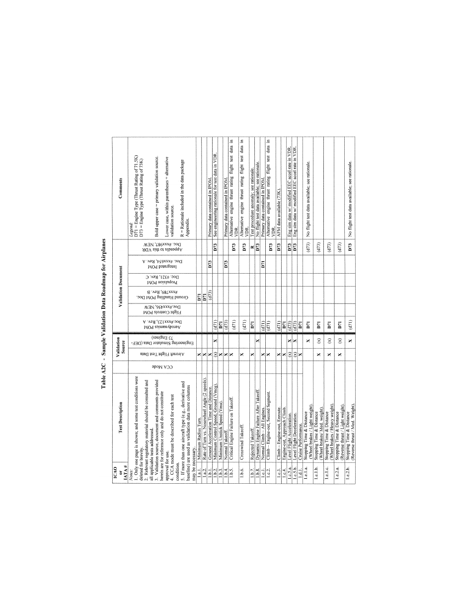
97
Federal Aviation Administration, DOT
Pt. 60, App. A
VerDate Sep<11>2014
14:00 Mar 14, 2024
Jkt 262047
PO 00000
Frm 00107
Fmt 8010
Sfmt 8006
Q:\14\14V2.TXT
PC31
ER09MY08.002</GPH>
aworley on LAPBH6H6L3 with DISTILLER

98
14 CFR Ch. I (1–1–24 Edition)
Pt. 60, App. A
B
EGIN
I
NFORMATION
llllllllllllllllllllllll
13. A
CCEPTANCE
G
UIDELINES FOR
A
LTERNATIVE
E
NGINES
D
ATA
.
a. Background
(1) For a new airplane type, the majority of
flight validation data are collected on the
first airplane configuration with a ‘‘base-
line’’ engine type. These data are then used
to validate all flight simulators representing
that airplane type.
(2) Additional flight test validation data
may be needed for flight simulators rep-
resenting an airplane with engines of a dif-
ferent type than the baseline, or for engines
with thrust rating that is different from pre-
viously validated configurations.
(3) When a flight simulator with alternate
engines is to be qualified, the QTG should
contain tests against flight test validation
data for selected cases where engine dif-
ferences are expected to be significant.
b. Approval Guidelines For Validating
Alternate Engine Applications
(1) The following guidelines apply to flight
simulators representing airplanes with alter-
nate engine applications or with more than
one engine type or thrust rating.
(2) Validation tests can be segmented into
two groups, those that are dependent on en-
gine type or thrust rating and those that are
not.
(3) For tests that are independent of engine
type or thrust rating, the QTG can be based
on validation data from any engine applica-
tion. Tests in this category should be des-
ignated as independent of engine type or
thrust rating.
(4) For tests that are affected by engine
type, the QTG should contain selected en-
gine-specific flight test data sufficient to
validate that particular airplane-engine con-
figuration. These effects may be due to en-
gine dynamic characteristics, thrust levels
or engine-related airplane configuration
changes. This category is primarily charac-
terized by variations between different en-
gine manufacturers’ products, but also in-
cludes differences due to significant engine
design changes from a previously flight-vali-
dated configuration within a single engine
type. See Table A2D, Alternate Engine Vali-
dation Flight Tests in this section for a list
of acceptable tests.
(5) Alternate engine validation data should
be based on flight test data, except as noted
in sub-paragraphs 13.c.(1) and (2), or where
other data are specifically allowed (e.g., en-
gineering simulator/simulation data). If cer-
tification of the flight characteristics of the
airplane with a new thrust rating (regardless
of percentage change) does require certifi-
cation flight testing with a comprehensive
stability and control flight instrumentation
package, then the conditions described in
Table A2D in this section should be obtained
from flight testing and presented in the
QTG. Flight test data, other than throttle
calibration data, are not required if the new
thrust rating is certified on the airplane
without need for a comprehensive stability
and control flight instrumentation package.
(6) As a supplement to the engine-specific
flight tests listed in Table A2D and baseline
engine-independent tests, additional engine-
specific engineering validation data should
be provided in the QTG, as appropriate, to fa-
cilitate running the entire QTG with the al-
ternate engine configuration. The sponsor
and the responsible Flight Standards office
should agree in advance on the specific vali-
dation tests to be supported by engineering
simulation data.
(7) A matrix or VDR should be provided
with the QTG indicating the appropriate val-
idation data source for each test.
(8) The flight test conditions in Table A2D
are appropriate and should be sufficient to
validate implementation of alternate en-
gines in a flight simulator.
E
ND
I
NFORMATION
llllllllllllllllllllllll
B
EGIN
QPS R
EQUIREMENT
c. Test Requirements
(1) The QTG must contain selected engine-
specific flight test data sufficient to validate
the alternative thrust level when:
(a) the engine type is the same, but the
thrust rating exceeds that of a previously
flight-test validated configuration by five
percent (5%) or more; or
(b) the engine type is the same, but the
thrust rating is less than the lowest pre-
viously flight-test validated rating by fifteen
percent (15%) or more. See Table A2D for a
list of acceptable tests.
(2) Flight test data is not required if the
thrust increase is greater than 5%, but flight
tests have confirmed that the thrust in-
crease does not change the airplane’s flight
characteristics.
(3) Throttle calibration data (i.e., com-
manded power setting parameter versus
throttle position) must be provided to vali-
date all alternate engine types and engine
thrust ratings that are higher or lower than
a previously validated engine. Data from a
test airplane or engineering test bench with
the correct engine controller (both hardware
and software) are required.
E
ND
QPS R
EQUIREMENT
llllllllllllllllllllllll
B
EGIN
QPS R
EQUIREMENT
VerDate Sep<11>2014
14:00 Mar 14, 2024
Jkt 262047
PO 00000
Frm 00108
Fmt 8010
Sfmt 8002
Q:\14\14V2.TXT
PC31
aworley on LAPBH6H6L3 with DISTILLER

99
Federal Aviation Administration, DOT
Pt. 60, App. A
T
ABLE
A2D—A
LTERNATIVE
E
NGINE
V
ALIDATION
F
LIGHT
T
ESTS
Entry No.
Test description
Alternative
engine type
Alternative
thrust rating
2
1.b.1., 1.b.4. ......................
Normal take-off/ground acceleration time and distance
X
X
1.b.2. .................................
V
mcg
, if performed for airplane certification
X
X
1.b.5. .................................
1.b.8. .................................
Engine-out take-off
Dynamic engine failure after take-off.
Either test
may be
performed.
X
1.b.7. .................................
Rejected take-off if performed for airplane certification
X
1.d.1. .................................
Cruise performance
X
1.f.1., 1.f.2. ........................
Engine acceleration and deceleration
X
X
2.a.7. .................................
Throttle calibration
1
X
X
2.c.1. .................................
Power change dynamics (acceleration)
X
X
2.d.1. .................................
V
mca
if performed for airplane certification
X
X
2.d.5. .................................
Engine inoperative trim
X
X
2.e.1. .................................
Normal landing
X
1
Must be provided for all changes in engine type or thrust rating; see paragraph 13.c.(3).
2
See paragraphs 13.c.(1) through 13.c.(3), for a definition of applicable thrust ratings.
E
ND
QPS R
EQUIREMENT
llllllllllllllllllllllll
B
EGIN
I
NFORMATION
14. A
CCEPTANCE
G
UIDELINES FOR
A
LTERNATIVE
A
VIONICS
(F
LIGHT
-R
ELATED
C
OMPUTERS AND
C
ONTROLLERS
)
a. Background
(1) For a new airplane type, the majority of
flight validation data are collected on the
first airplane configuration with a ‘‘base-
line’’ flight-related avionics ship-set; (see
subparagraph b.(2) of this section). These
data are then used to validate all flight sim-
ulators representing that airplane type.
(2) Additional validation data may be re-
quired for flight simulators representing an
airplane with avionics of a different hard-
ware design than the baseline, or a different
software revision than previously validated
configurations.
(3) When a flight simulator with additional
or alternate avionics configurations is to be
qualified, the QTG should contain tests
against validation data for selected cases
where avionics differences are expected to be
significant.
b. Approval Guidelines for Validating
Alternate Avionics
(1) The following guidelines apply to flight
simulators representing airplanes with a re-
vised avionics configuration, or more than
one avionics configuration.
(2) The baseline validation data should be
based on flight test data, except where other
data are specifically allowed (e.g., engineer-
ing flight simulator data).
(3) The airplane avionics can be segmented
into two groups, systems or components
whose functional behavior contributes to the
aircraft response presented in the QTG re-
sults, and systems that do not. The following
avionics are examples of contributory sys-
tems for which hardware design changes or
software revisions may lead to significant
differences in the aircraft response relative
to the baseline avionics configuration:
Flight control computers and controllers for
engines, autopilot, braking system,
nosewheel steering system, and high lift sys-
tem. Related avionics such as stall warning
and augmentation systems should also be
considered.
(4) The acceptability of validation data
used in the QTG for an alternative avionics
fit should be determined as follows:
(a) For changes to an avionics system or
component that do not affect QTG validation
test response, the QTG test can be based on
validation data from the previously vali-
dated avionics configuration.
(b) For an avionics change to a contribu-
tory system, where a specific test is not af-
fected by the change (e.g., the avionics
change is a Built In Test Equipment (BITE)
update or a modification in a different flight
phase), the QTG test can be based on valida-
tion data from the previously-validated avi-
onics configuration. The QTG should include
authoritative justification (e.g., from the
airplane manufacturer or system supplier)
that this avionics change does not affect the
test.
(c) For an avionics change to a contribu-
tory system, the QTG may be based on vali-
dation data from the previously-validated
avionics configuration if no new
functionality is added and the impact of the
avionics change on the airplane response is
small and based on acceptable aeronautical
principles with proven success history and
valid outcomes. This should be supplemented
with avionics-specific validation data from
the airplane manufacturer’s engineering
VerDate Sep<11>2014
14:00 Mar 14, 2024
Jkt 262047
PO 00000
Frm 00109
Fmt 8010
Sfmt 8002
Q:\14\14V2.TXT
PC31
aworley on LAPBH6H6L3 with DISTILLER

100
14 CFR Ch. I (1–1–24 Edition)
Pt. 60, App. A
simulation, generated with the revised avi-
onics configuration. The QTG should also in-
clude an explanation of the nature of the
change and its effect on the airplane re-
sponse.
(d) For an avionics change to a contribu-
tory system that significantly affects some
tests in the QTG or where new functionality
is added, the QTG should be based on valida-
tion data from the previously validated avi-
onics configuration and supplemental avi-
onics-specific flight test data sufficient to
validate the alternate avionics revision. Ad-
ditional flight test validation data may not
be needed if the avionics changes were cer-
tified without the need for testing with a
comprehensive flight instrumentation pack-
age. The airplane manufacturer should co-
ordinate flight simulator data requirements,
in advance with the responsible Flight
Standards office.
(5) A matrix or ‘‘roadmap’’ should be pro-
vided with the QTG indicating the appro-
priate validation data source for each test.
The roadmap should include identification of
the revision state of those contributory avi-
onics systems that could affect specific test
responses if changed.
15. T
RANSPORT
D
ELAY
T
ESTING
a. This paragraph explains how to deter-
mine the introduced transport delay through
the flight simulator system so that it does
not exceed a specific time delay. The trans-
port delay should be measured from control
inputs through the interface, through each
of the host computer modules and back
through the interface to motion, flight in-
strument, and visual systems. The transport
delay should not exceed the maximum allow-
able interval.
b. Four specific examples of transport
delay are:
(1) Simulation of classic non-computer
controlled aircraft;
(2) Simulation of computer controlled air-
craft using real airplane black boxes;
(3) Simulation of computer controlled air-
craft using software emulation of airplane
boxes;
(4) Simulation using software avionics or
re-hosted instruments.
c. Figure A2C illustrates the total trans-
port delay for a non-computer-controlled air-
plane or the classic transport delay test.
Since there are no airplane-induced delays
for this case, the total transport delay is
equivalent to the introduced delay.
d. Figure A2D illustrates the transport
delay testing method using the real airplane
controller system.
e. To obtain the induced transport delay
for the motion, instrument and visual signal,
the delay induced by the airplane controller
should be subtracted from the total trans-
port delay. This difference represents the in-
troduced delay and should not exceed the
standards prescribed in Table A1A.
f. Introduced transport delay is measured
from the flight deck control input to the re-
action of the instruments and motion and
visual systems (See Figure A2C).
g. The control input may also be intro-
duced after the airplane controller system
and the introduced transport delay measured
directly from the control input to the reac-
tion of the instruments, and simulator mo-
tion and visual systems (See Figure A2D).
h. Figure A2E illustrates the transport
delay testing method used on a flight simu-
lator that uses a software emulated airplane
controller system.
i. It is not possible to measure the intro-
duced transport delay using the simulated
airplane controller system architecture for
the pitch, roll and yaw axes. Therefore, the
signal should be measured directly from the
pilot controller. The flight simulator manu-
facturer should measure the total transport
delay and subtract the inherent delay of the
actual airplane components because the real
airplane controller system has an inherent
delay provided by the airplane manufacturer.
The flight simulator manufacturer should
ensure that the introduced delay does not ex-
ceed the standards prescribed in Table A1A.
j. Special measurements for instrument
signals for flight simulators using a real air-
plane instrument display system instead of a
simulated or re-hosted display. For flight in-
strument systems, the total transport delay
should be measured and the inherent delay of
the actual airplane components subtracted
to ensure that the introduced delay does not
exceed the standards prescribed in Table
A1A.
(1) Figure A2FA illustrates the transport
delay procedure without airplane display
simulation. The introduced delay consists of
the delay between the control movement and
the instrument change on the data bus.
(2) Figure A2FB illustrates the modified
testing method required to measure intro-
duced delay due to software avionics or re-
hosted instruments. The total simulated in-
strument transport delay is measured and
the airplane delay should be subtracted from
this total. This difference represents the in-
troduced delay and should not exceed the
standards prescribed in Table A1A. The in-
herent delay of the airplane between the
data bus and the displays is indicated in fig-
ure A2FA. The display manufacturer should
provide this delay time.
k. Recorded signals. The signals recorded
to conduct the transport delay calculations
should be explained on a schematic block
diagram. The flight simulator manufacturer
should also provide an explanation of why
each signal was selected and how they relate
to the above descriptions.
l. Interpretation of results. Flight simu-
lator results vary over time from test to test
VerDate Sep<11>2014
14:00 Mar 14, 2024
Jkt 262047
PO 00000
Frm 00110
Fmt 8010
Sfmt 8002
Q:\14\14V2.TXT
PC31
aworley on LAPBH6H6L3 with DISTILLER

101
Federal Aviation Administration, DOT
Pt. 60, App. A
due to ‘‘sampling uncertainty.’’ All flight
simulators run at a specific rate where all
modules are executed sequentially in the
host computer. The flight controls input can
occur at any time in the iteration, but these
data will not be processed before the start of
the new iteration. For example, a flight sim-
ulator running at 60 Hz may have a dif-
ference of as much as 16.67 msec between test
results. This does not mean that the test has
failed. Instead, the difference is attributed to
variations in input processing. In some con-
ditions, the host simulator and the visual
system do not run at the same iteration rate,
so the output of the host computer to the
visual system will not always be syn-
chronized.
m. The transport delay test should account
for both daylight and night modes of oper-
ation of the visual system. In both cases, the
tolerances prescribed in Table A1A must be
met and the motion response should occur
before the end of the first video scan con-
taining new information.
VerDate Sep<11>2014
14:00 Mar 14, 2024
Jkt 262047
PO 00000
Frm 00111
Fmt 8010
Sfmt 8002
Q:\14\14V2.TXT
PC31
aworley on LAPBH6H6L3 with DISTILLER
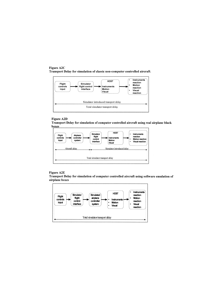
102
14 CFR Ch. I (1–1–24 Edition)
Pt. 60, App. A
VerDate Sep<11>2014
14:00 Mar 14, 2024
Jkt 262047
PO 00000
Frm 00112
Fmt 8010
Sfmt 8006
Q:\14\14V2.TXT
PC31
ER09MY08.003</GPH>
aworley on LAPBH6H6L3 with DISTILLER
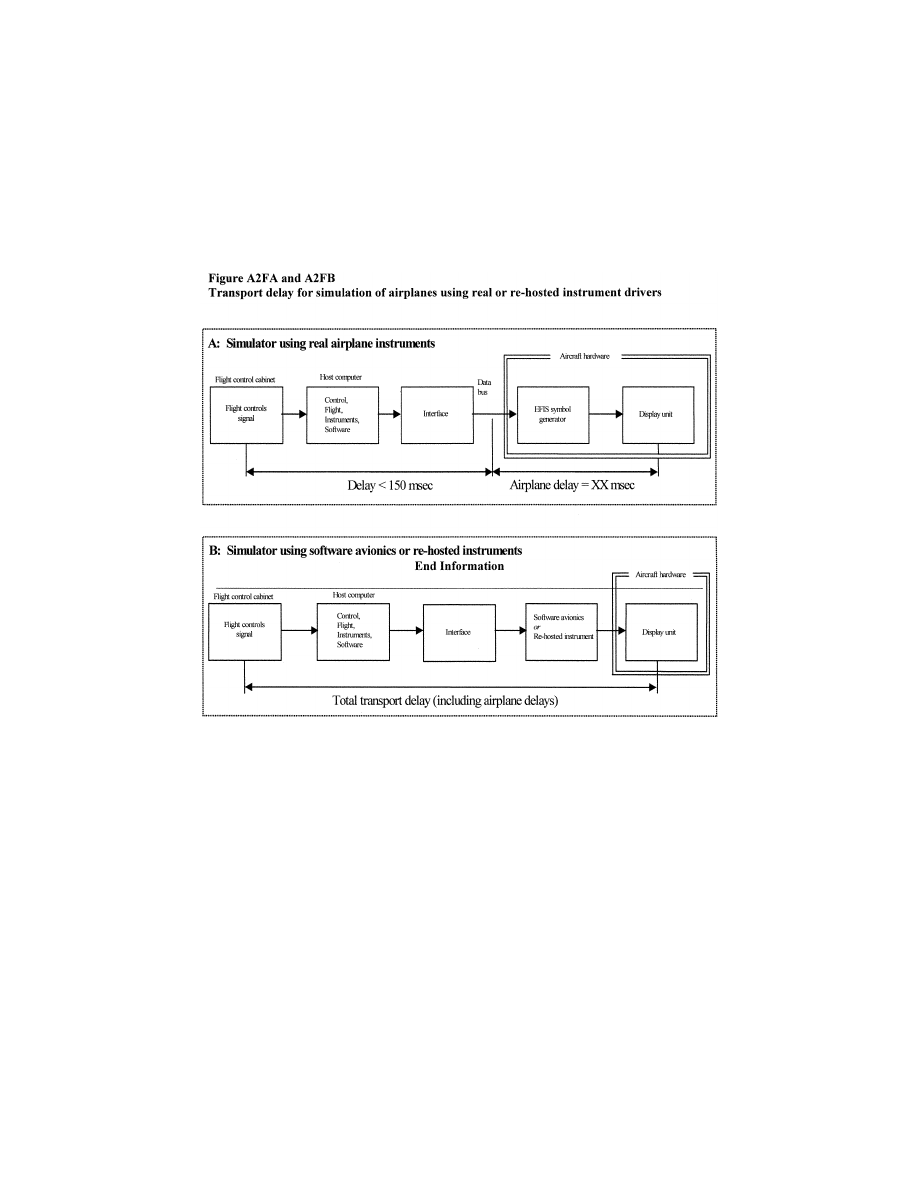
103
Federal Aviation Administration, DOT
Pt. 60, App. A
llllllllllllllllllllllll
B
EGIN
I
NFORMATION
16. C
ONTINUING
Q
UALIFICATION
E
VALUATIONS
—
V
ALIDATION
T
EST
D
ATA
P
RESENTATION
a. Background
(1) The MQTG is created during the initial
evaluation of a flight simulator. This is the
master document, as amended, to which
flight simulator continuing qualification
evaluation test results are compared.
(2) The currently accepted method of pre-
senting continuing qualification evaluation
test results is to provide flight simulator re-
sults over-plotted with reference data. Test
results are carefully reviewed to determine if
the test is within the specified tolerances.
This can be a time consuming process, par-
ticularly when reference data exhibits rapid
variations or an apparent anomaly requiring
engineering judgment in the application of
the tolerances. In these cases, the solution is
to compare the results to the MQTG. The
continuing qualification results are com-
pared to the results in the MQTG for accept-
ance. The flight simulator operator and the
responsible Flight Standards office should
look for any change in the flight simulator
performance since initial qualification.
b. Continuing Qualification Evaluation Test
Results Presentation
(1) Flight simulator operators are encour-
aged to over-plot continuing qualification
validation test results with MQTG flight
simulator results recorded during the initial
evaluation and as amended. Any change in a
validation test will be readily apparent. In
addition to plotting continuing qualification
validation test and MQTG results, operators
may elect to plot reference data as well.
(2) There are no suggested tolerances be-
tween flight simulator continuing qualifica-
tion and MQTG validation test results. In-
vestigation of any discrepancy between the
MQTG and continuing qualification flight
simulator performance is left to the discre-
tion of the flight simulator operator and the
responsible Flight Standards office.
VerDate Sep<11>2014
14:00 Mar 14, 2024
Jkt 262047
PO 00000
Frm 00113
Fmt 8010
Sfmt 8002
Q:\14\14V2.TXT
PC31
ER09MY08.004</GPH>
aworley on LAPBH6H6L3 with DISTILLER

104
14 CFR Ch. I (1–1–24 Edition)
Pt. 60, App. A
(3) Differences between the two sets of re-
sults, other than variations attributable to
repeatability issues that cannot be ex-
plained, should be investigated.
(4) The flight simulator should retain the
ability to over-plot both automatic and man-
ual validation test results with reference
data.
E
ND
I
NFORMATION
llllllllllllllllllllllll
B
EGIN
QPS R
EQUIREMENTS
17. A
LTERNATIVE
D
ATA
S
OURCES
, P
ROCE
-
DURES
,
AND
I
NSTRUMENTATION
: L
EVEL
A
AND
L
EVEL
B S
IMULATORS
O
NLY
a. Sponsors are not required to use the al-
ternative data sources, procedures, and in-
strumentation. However, a sponsor may
choose to use one or more of the alternative
sources, procedures, and instrumentation de-
scribed in Table A2E.
E
ND
QPS R
EQUIREMENTS
llllllllllllllllllllllll
B
EGIN
I
NFORMATION
b. It has become standard practice for ex-
perienced simulator manufacturers to use
modeling techniques to establish data bases
for new simulator configurations while
awaiting the availability of actual flight test
data. The data generated from the aero-
dynamic modeling techniques is then com-
pared to the flight test data when it becomes
available. The results of such comparisons
have become increasingly consistent, indi-
cating that these techniques, applied with
the appropriate experience, are dependable
and accurate for the development of aero-
dynamic models for use in Level A and Level
B simulators.
c. Based on this history of successful com-
parisons, the responsible Flight Standards
office has concluded that those who are expe-
rienced in the development of aerodynamic
models may use modeling techniques to alter
the method for acquiring flight test data for
Level A or Level B simulators.
d. The information in Table A2E (Alter-
native Data Sources, Procedures, and Instru-
mentation) is presented to describe an ac-
ceptable alternative to data sources for sim-
ulator modeling and validation and an ac-
ceptable alternative to the procedures and
instrumentation traditionally used to gather
such modeling and validation data.
(1) Alternative data sources that may be
used for part or all of a data requirement are
the Airplane Maintenance Manual, the Air-
plane Flight Manual (AFM), Airplane Design
Data, the Type Inspection Report (TIR), Cer-
tification Data or acceptable supplemental
flight test data.
(2) The sponsor should coordinate with the
responsible Flight Standards office prior to
using alternative data sources in a flight
test or data gathering effort.
e. The responsible Flight Standards office
position regarding the use of these alter-
native data sources, procedures, and instru-
mentation is based on the following pre-
sumptions:
(1) Data gathered through the alternative
means does not require angle of attack
(AOA) measurements or control surface posi-
tion measurements for any flight test. How-
ever, AOA can be sufficiently derived if the
flight test program ensures the collection of
acceptable level, unaccelerated, trimmed
flight data. All of the simulator time history
tests that begin in level, unaccelerated, and
trimmed flight, including the three basic
trim tests and ‘‘fly-by’’ trims, can be a suc-
cessful validation of angle of attack by com-
parison with flight test pitch angle. (Note:
Due to the criticality of angle of attack in
the development of the ground effects model,
particularly critical for normal landings and
landings involving cross-control input appli-
cable to Level B simulators, stable ‘‘fly-by’’
trim data will be the acceptable norm for
normal and cross-control input landing ob-
jective data for these applications.)
(2) The use of a rigorously defined and fully
mature simulation controls system model
that includes accurate gearing and cable
stretch characteristics (where applicable),
determined from actual aircraft measure-
ments. Such a model does not require con-
trol surface position measurements in the
flight test objective data in these limited ap-
plications.
f. The sponsor is urged to contact the re-
sponsible Flight Standards office for clari-
fication of any issue regarding airplanes
with reversible control systems. Table A2E is
not applicable to Computer Controlled Air-
craft FFSs.
g. Utilization of these alternate data
sources, procedures, and instrumentation
(Table A2E) does not relieve the sponsor
from compliance with the balance of the in-
formation contained in this document rel-
ative to Level A or Level B FFSs.
h. The term ‘‘inertial measurement sys-
tem’’ is used in the following table to include
the use of a functional global positioning
system (GPS).
i. Synchronized video for the use of alter-
native data sources, procedures, and instru-
mentation should have:
(1) Sufficient resolution to allow mag-
nification of the display to make appropriate
measurement and comparisons; and
(2) Sufficient size and incremental mark-
ing to allow similar measurement and com-
parison. The detail provided by the video
should provide sufficient clarity and accu-
racy to measure the necessary parameter(s)
to at least
1
⁄
2
of the tolerance authorized for
VerDate Sep<11>2014
14:00 Mar 14, 2024
Jkt 262047
PO 00000
Frm 00114
Fmt 8010
Sfmt 8002
Q:\14\14V2.TXT
PC31
aworley on LAPBH6H6L3 with DISTILLER

105
Federal Aviation Administration, DOT
Pt. 60, App. A
the specific test being conducted and allow
an integration of the parameter(s) in ques-
tion to obtain a rate of change.
E
ND
I
NFORMATION
llllllllllllllllllllllll
T
ABLE
A2E—A
LTERNATIVE
D
ATA
S
OURCES
, P
ROCEDURES
,
AND
I
NSTRUMENTATION
QPS REQUIREMENTS
The standards in this table are required if the data gathering methods described in paragraph
9 of
Appendix A are not used.
Information
Table of objective tests
Sim level
Alternative data sources, procedures, and
instrumentation
Notes
Test entry number and title
A
B
1.a.1. Performance. Taxi. Min-
imum Radius turn.
X
X
TIR, AFM, or Design data may be used.
1.a.2. Performance. Taxi Rate
of Turn vs. Nosewheel Steer-
ing Angle.
X
Data may be acquired by using a constant
tiller position, measured with a pro-
tractor or full rudder pedal application
for steady state turn, and synchronized
video of heading indicator. If less than
full rudder pedal is used, pedal position
must be recorded..
A single procedure may not be
adequate for all airplane
steering systems, therefore
appropriate measurement
procedures must be devised
and proposed for the respon-
sible Flight Standards office
concurrence.
1.b.1. Performance. Takeoff.
Ground Acceleration Time
and Distance.
X
X
Preliminary certification data may be
used. Data may be acquired by using a
stop watch, calibrated airspeed, and
runway markers during a takeoff with
power set before brake release. Power
settings may be hand recorded. If an in-
ertial measurement system is installed,
speed and distance may be derived
from acceleration measurements.
1.b.2. Performance. Takeoff.
Minimum Control Speed—
ground (V
mcg
) using aero-
dynamic controls only (per ap-
plicable airworthiness stand-
ard) or low speed, engine in-
operative ground control char-
acteristics.
X
X
Data may be acquired by using an inertial
measurement system and a syn-
chronized video of calibrated airplane
instruments and force/position measure-
ments of flight deck controls.
Rapid throttle reductions at
speeds near V
mcg
may be
used while recording appro-
priate parameters. The
nosewheel must be free to
caster, or equivalently freed
of sideforce generation.
1.b.3. Performance. Takeoff.
Minimum Unstick Speed (V
mu
)
or equivalent test to dem-
onstrate early rotation takeoff
characteristics.
X
X
Data may be acquired by using an inertial
measurement system and a syn-
chronized video of calibrated airplane
instruments and the force/position
measurements of flight deck controls.
1.b.4. Performance. Takeoff.
Normal Takeoff.
X
X
Data may be acquired by using an inertial
measurement system and a syn-
chronized video of calibrated airplane
instruments and force/position measure-
ments of flight deck controls. AOA can
be calculated from pitch attitude and
flight path.
1.b.5. Performance. Takeoff.
Critical Engine Failure during
Takeoff.
X
X
Data may be acquired by using an inertial
measurement system and a syn-
chronized video of calibrated airplane
instruments and force/position measure-
ments of flight deck controls.
Record airplane dynamic re-
sponse to engine failure and
control inputs required to cor-
rect flight path.
1.b.6. Performance. Takeoff.
Crosswind Takeoff.
X
X
Data may be acquired by using an inertial
measurement system and a syn-
chronized video of calibrated airplane
instruments and force/position measure-
ments of flight deck controls.
The ‘‘1:7 law’’ to 100 feet (30
meters) is an acceptable
wind profile.
VerDate Sep<11>2014
14:00 Mar 14, 2024
Jkt 262047
PO 00000
Frm 00115
Fmt 8010
Sfmt 8002
Q:\14\14V2.TXT
PC31
aworley on LAPBH6H6L3 with DISTILLER

106
14 CFR Ch. I (1–1–24 Edition)
Pt. 60, App. A
T
ABLE
A2E—A
LTERNATIVE
D
ATA
S
OURCES
, P
ROCEDURES
,
AND
I
NSTRUMENTATION
—Continued
QPS REQUIREMENTS
The standards in this table are required if the data gathering methods described in paragraph
9 of
Appendix A are not used.
Information
Table of objective tests
Sim level
Alternative data sources, procedures, and
instrumentation
Notes
Test entry number and title
A
B
1.b.7. Performance. Takeoff.
Rejected Takeoff.
X
X
Data may be acquired with a syn-
chronized video of calibrated airplane
instruments, thrust lever position, en-
gine parameters, and distance (e.g.,
runway markers). A stop watch is re-
quired..
1.c. 1. Performance. Climb. Nor-
mal Climb all engines oper-
ating..
X
X
Data may be acquired with a syn-
chronized video of calibrated airplane
instruments and engine power through-
out the climb range.
1.c.2. Performance. Climb. One
engine Inoperative Climb.
X
X
Data may be acquired with a syn-
chronized video of calibrated airplane
instruments and engine power through-
out the climb range.
1.c.4. Performance. Climb. One
Engine Inoperative Approach
Climb (if operations in icing
conditions are authorized).
X
X
Data may be acquired with a syn-
chronized video of calibrated airplane
instruments and engine power through-
out the climb range.
1.d.1. Cruise/Descent. Level
flight acceleration..
X
X
Data may be acquired with a syn-
chronized video of calibrated airplane
instruments, thrust lever position, en-
gine parameters, and elapsed time.
1.d.2. Cruise/Descent. Level
flight deceleration..
X
X
Data may be acquired with a syn-
chronized video of calibrated airplane
instruments, thrust lever position, en-
gine parameters, and elapsed time.
1.d.4. Cruise/Descent. Idle de-
scent.
X
X
Data may be acquired with a syn-
chronized video of calibrated airplane
instruments, thrust lever position, en-
gine parameters, and elapsed time.
1.d.5. Cruise/Descent. Emer-
gency Descent.
X
X
Data may be acquired with a syn-
chronized video of calibrated airplane
instruments, thrust lever position, en-
gine parameters, and elapsed time.
1.e.1. Performance. Stopping.
Deceleration time and dis-
tance, using manual applica-
tion of wheel brakes and no
reverse thrust on a dry run-
way.
X
X
Data may be acquired during landing tests
using a stop watch, runway markers,
and a synchronized video of calibrated
airplane instruments, thrust lever posi-
tion and the pertinent parameters of en-
gine power.
1.e.2. Performance. Ground.
Deceleration Time and Dis-
tance, using reverse thrust
and no wheel brakes.
X
X
Data may be acquired during landing tests
using a stop watch, runway markers,
and a synchronized video of calibrated
airplane instruments, thrust lever posi-
tion and pertinent parameters of engine
power.
1.f.1. Performance. Engines.
Acceleration.
X
X
Data may be acquired with a syn-
chronized video recording of engine in-
struments and throttle position.
1.f.2. Performance. Engines.
Deceleration.
X
X
Data may be acquired with a syn-
chronized video recording of engine in-
struments and throttle position.
VerDate Sep<11>2014
14:00 Mar 14, 2024
Jkt 262047
PO 00000
Frm 00116
Fmt 8010
Sfmt 8002
Q:\14\14V2.TXT
PC31
aworley on LAPBH6H6L3 with DISTILLER

107
Federal Aviation Administration, DOT
Pt. 60, App. A
T
ABLE
A2E—A
LTERNATIVE
D
ATA
S
OURCES
, P
ROCEDURES
,
AND
I
NSTRUMENTATION
—Continued
QPS REQUIREMENTS
The standards in this table are required if the data gathering methods described in paragraph
9 of
Appendix A are not used.
Information
Table of objective tests
Sim level
Alternative data sources, procedures, and
instrumentation
Notes
Test entry number and title
A
B
2.a.1.a.Handling Qualities. Stat-
ic Control Checks. Pitch Con-
troller Position vs. Force and
Surface Position Calibration.
X
X
Surface position data may be acquired
from flight data recorder (FDR) sensor
or, if no FDR sensor, at selected, sig-
nificant column positions (encom-
passing significant column position data
points), acceptable to the responsible
Flight Standards office, using a control
surface protractor on the ground. Force
data may be acquired by using a hand
held force gauge at the same column
position data points..
For airplanes with reversible
control systems, surface po-
sition data acquisition should
be accomplished with winds
less than 5 kts.
2.a.2.a. Handling Qualities. Stat-
ic Control Checks. Roll Con-
troller Position vs. Force and
Surface Position Calibration.
X
X
Surface position data may be acquired
from flight data recorder (FDR) sensor
or, if no FDR sensor, at selected, sig-
nificant wheel positions (encompassing
significant wheel position data points),
acceptable to the responsible Flight
Standards office, using a control sur-
face protractor on the ground. Force
data may be acquired by using a hand
held force gauge at the same wheel po-
sition data points..
For airplanes with reversible
control systems, surface po-
sition data acquisition should
be accomplished with winds
less than 5 kts.
2.a.3.a.Handling Qualities. Stat-
ic Control Checks. Rudder
Pedal Position vs. Force and
Surface Position Calibration.
X
X
Surface position data may be acquired
from flight data recorder (FDR) sensor
or, if no FDR sensor, at selected, sig-
nificant rudder pedal positions (encom-
passing significant rudder pedal position
data points), acceptable to the respon-
sible Flight Standards office, using a
control surface protractor on the
ground. Force data may be acquired by
using a hand held force gauge at the
same rudder pedal position data points..
For airplanes with reversible
control systems, surface po-
sition data acquisition should
be accomplished with winds
less than 5 kts.
2.a.4. Handling Qualities. Static
Control Checks. Nosewheel
Steering Controller Force and
Position.
X
X
Breakout data may be acquired with a
hand held force gauge. The remainder
of the force to the stops may be cal-
culated if the force gauge and a pro-
tractor are used to measure force after
breakout for at least 25% of the total
displacement capability.
2.a.5. Handling Qualities. Static
Control Checks. Rudder
Pedal Steering Calibration.
X
X
Data may be acquired through the use of
force pads on the rudder pedals and a
pedal position measurement device, to-
gether with design data for nosewheel
position.
2.a.6. Handling Qualities. Static
Control Checks. Pitch Trim In-
dicator vs. Surface Position
Calibration.
X
X
Data may be acquired through calcula-
tions.
2.a.7. Handling qualities. Static
control tests. Pitch trim rate.
X
X
Data may be acquired by using a syn-
chronized video of pitch trim indication
and elapsed time through range of trim
indication.
2.a.8. Handling Qualities. Static
Control tests. Alignment of
Flight deck Throttle Lever
Angle vs. Selected engine pa-
rameter.
X
X
Data may be acquired through the use of
a temporary throttle quadrant scale to
document throttle position. Use a syn-
chronized video to record steady state
instrument readings or hand-record
steady state engine performance read-
ings.
VerDate Sep<11>2014
14:00 Mar 14, 2024
Jkt 262047
PO 00000
Frm 00117
Fmt 8010
Sfmt 8002
Q:\14\14V2.TXT
PC31
aworley on LAPBH6H6L3 with DISTILLER

108
14 CFR Ch. I (1–1–24 Edition)
Pt. 60, App. A
T
ABLE
A2E—A
LTERNATIVE
D
ATA
S
OURCES
, P
ROCEDURES
,
AND
I
NSTRUMENTATION
—Continued
QPS REQUIREMENTS
The standards in this table are required if the data gathering methods described in paragraph
9 of
Appendix A are not used.
Information
Table of objective tests
Sim level
Alternative data sources, procedures, and
instrumentation
Notes
Test entry number and title
A
B
2.a.9. Handling qualities. Static
control tests. Brake pedal po-
sition vs. force and brake sys-
tem pressure calibration.
X
X
Use of design or predicted data is accept-
able. Data may be acquired by meas-
uring deflection at ‘‘zero’’ and ‘‘max-
imum’’ and calculating deflections be-
tween the extremes using the airplane
design data curve.
2.c.1. Handling qualities. Longi-
tudinal control tests. Power
change dynamics.
X
X
Data may be acquired by using an inertial
measurement system and a syn-
chronized video of calibrated airplane
instruments and throttle position.
2.c.2. Handling qualities. Longi-
tudinal control tests. Flap/slat
change dynamics.
X
X
Data may be acquired by using an inertial
measurement system and a syn-
chronized video of calibrated airplane
instruments and flap/slat position.
2.c.3. Handling qualities. Longi-
tudinal control tests. Spoiler/
speedbrake change dynamics.
X
X
Data may be acquired by using an inertial
measurement system and a syn-
chronized video of calibrated airplane
instruments and spoiler/speedbrake po-
sition.
2.c.4. Handling qualities. Longi-
tudinal control tests. Gear
change dynamics.
X
X
Data may be acquired by using an inertial
measurement system and a syn-
chronized video of calibrated airplane
instruments and gear position.
2.c.5. Handling qualities. Longi-
tudinal control tests. Longitu-
dinal trim.
X
X
Data may be acquired through use of an
inertial measurement system and a syn-
chronized video of flight deck controls
position (previously calibrated to show
related surface position) and the engine
instrument readings.
2.c.6. Handling qualities. Longi-
tudinal control tests. Longitu-
dinal maneuvering stability
(stick force/g).
X
X
Data may be acquired through the use of
an inertial measurement system and a
synchronized video of calibrated air-
plane instruments; a temporary, high
resolution bank angle scale affixed to
the attitude indicator; and a wheel and
column force measurement indication.
2.c.7. Handling qualities. Longi-
tudinal control tests. Longitu-
dinal static stability.
X
X
Data may be acquired through the use of
a synchronized video of airplane flight
instruments and a hand held force
gauge.
2.c.8. Handling qualities. Longi-
tudinal control tests. Stall
characteristics.
X
X
Data may be acquired through a syn-
chronized video recording of a stop
watch and calibrated airplane airspeed
indicator. Hand-record the flight condi-
tions and airplane configuration.
Airspeeds may be cross
checked with those in the
TIR and AFM.
2.c.9. Handling qualities. Longi-
tudinal control tests. Phugoid
dynamics.
X
X
Data may be acquired by using an inertial
measurement system and a syn-
chronized video of calibrated airplane
instruments and force/position measure-
ments of flight deck controls.
2.c.10. Handling qualities. Lon-
gitudinal control tests. Short
period dynamics.
X
Data may be acquired by using an inertial
measurement system and a syn-
chronized video of calibrated airplane
instruments and force/position measure-
ments of flight deck controls.
VerDate Sep<11>2014
14:00 Mar 14, 2024
Jkt 262047
PO 00000
Frm 00118
Fmt 8010
Sfmt 8002
Q:\14\14V2.TXT
PC31
aworley on LAPBH6H6L3 with DISTILLER

109
Federal Aviation Administration, DOT
Pt. 60, App. A
T
ABLE
A2E—A
LTERNATIVE
D
ATA
S
OURCES
, P
ROCEDURES
,
AND
I
NSTRUMENTATION
—Continued
QPS REQUIREMENTS
The standards in this table are required if the data gathering methods described in paragraph
9 of
Appendix A are not used.
Information
Table of objective tests
Sim level
Alternative data sources, procedures, and
instrumentation
Notes
Test entry number and title
A
B
2.d.1. Handling qualities. Lateral
directional tests. Minimum
control speed, air (V
mca
or
V
mci
), per applicable airworthi-
ness standard or Low speed
engine inoperative handling
characteristics in the air.
X
X
Data may be acquired by using an inertial
measurement system and a syn-
chronized video of calibrated airplane
instruments and force/position measure-
ments of flight deck controls.
2.d.2. Handling qualities. Lateral
directional tests. Roll re-
sponse (rate).
X
X
Data may be acquired by using an inertial
measurement system and a syn-
chronized video of calibrated airplane
instruments and force/position measure-
ments of flight deck lateral controls.
May be combined with step
input of flight deck roll con-
troller test, 2.d.3.
2.d.3. Handling qualities. Lateral
directional tests. Roll re-
sponse to flight deck roll con-
troller step input.
X
X
Data may be acquired by using an inertial
measurement system and a syn-
chronized video of calibrated airplane
instruments and force/position measure-
ments of flight deck lateral controls.
2.d.4. Handling qualities. Lateral
directional tests. Spiral sta-
bility.
X
X
Data may be acquired by using an inertial
measurement system and a syn-
chronized video of calibrated airplane
instruments; force/position measure-
ments of flight deck controls; and a stop
watch.
2.d.5. Handling qualities. Lateral
directional tests. Engine inop-
erative trim.
X
X
Data may be hand recorded in-flight using
high resolution scales affixed to trim
controls that have been calibrated on
the ground using protractors on the
control/trim surfaces with winds less
than 5 kts.OR Data may be acquired
during second segment climb (with
proper pilot control input for an engine-
out condition) by using a synchronized
video of calibrated airplane instruments
and force/position measurements of
flight deck controls.
Trimming during second seg-
ment climb is not a certifi-
cation task and should not be
conducted until a safe alti-
tude is reached.
2.d.6. Handling qualities. Lateral
directional tests. Rudder re-
sponse.
X
X
Data may be acquired by using an inertial
measurement system and a syn-
chronized video of calibrated airplane
instruments and force/position measure-
ments of rudder pedals.
2.d.7. Handling qualities. Lateral
directional tests. Dutch roll,
(yaw damper OFF).
X
X
Data may be acquired by using an inertial
measurement system and a syn-
chronized video of calibrated airplane
instruments and force/position measure-
ments of flight deck controls.
2.d.8. Handling qualities. Lateral
directional tests. Steady state
sideslip.
X
X
Data may be acquired by using an inertial
measurement system and a syn-
chronized video of calibrated airplane
instruments and force/position measure-
ments of flight deck controls.
Ground track and wind corrected heading
may be used for sideslip angle.
2.e.1. Handling qualities. Land-
ings. Normal landing.
X
Data may be acquired by using an inertial
measurement system and a syn-
chronized video of calibrated airplane
instruments and force/position measure-
ments of flight deck controls.
VerDate Sep<11>2014
14:00 Mar 14, 2024
Jkt 262047
PO 00000
Frm 00119
Fmt 8010
Sfmt 8002
Q:\14\14V2.TXT
PC31
aworley on LAPBH6H6L3 with DISTILLER

110
14 CFR Ch. I (1–1–24 Edition)
Pt. 60, App. A
T
ABLE
A2E—A
LTERNATIVE
D
ATA
S
OURCES
, P
ROCEDURES
,
AND
I
NSTRUMENTATION
—Continued
QPS REQUIREMENTS
The standards in this table are required if the data gathering methods described in paragraph
9 of
Appendix A are not used.
Information
Table of objective tests
Sim level
Alternative data sources, procedures, and
instrumentation
Notes
Test entry number and title
A
B
2.e.3. Handling qualities. Land-
ings. Crosswind landing.
X
Data may be acquired by using an inertial
measurement system and a syn-
chronized video of calibrated airplane
instruments and force/position measure-
ments of flight deck controls.
2.e.4. Handling qualities. Land-
ings. One engine inoperative
landing.
X
Data may be acquired by using an inertial
measurement system and a syn-
chronized video of calibrated airplane
instruments and the force/position
measurements of flight deck controls.
Normal and lateral accelerations may
be recorded in lieu of AOA and sideslip.
2.e.5. Handling qualities. Land-
ings. Autopilot landing (if ap-
plicable).
..........
X
Data may be acquired by using an inertial
measurement system and a syn-
chronized video of calibrated airplane
instruments and force/position measure-
ments of flight deck controls.Normal
and lateral accelerations may be re-
corded in lieu of AOA and sideslip.
2.e.6. Handling qualities. Land-
ings. All engines operating,
autopilot, go around.
X
Data may be acquired by using an inertial
measurement system and a syn-
chronized video of calibrated airplane
instruments and force/position measure-
ments of flight deck controls. Normal
and lateral accelerations may be re-
corded in lieu of AOA and sideslip.
2.e.7. Handling qualities. Land-
ings. One engine inoperative
go around.
X
Data may be acquired by using an inertial
measurement system and a syn-
chronized video of calibrated airplane
instruments and force/position measure-
ments of flight deck controls. Normal
and lateral accelerations may be re-
corded in lieu of AOA and sideslip.
2.e.8. Handling qualities. Land-
ings. Directional control (rud-
der effectiveness with sym-
metric thrust).
X
Data may be acquired by using an inertial
measurement system and a syn-
chronized video of calibrated airplane
instruments and force/position measure-
ments of flight deck controls. Normal
and lateral accelerations may be re-
corded in lieu of AOA and sideslip.
2.e.9. Handling qualities. Land-
ings. Directional control (rud-
der effectiveness with asym-
metric reverse thrust).
X
Data may be acquired by using an inertial
measurement system and a syn-
chronized video of calibrated airplane
instruments and force/position measure-
ments of flight deck controls. Normal
and lateral accelerations may be re-
corded in lieu of AOA and sideslip.
2.f. Handling qualities. Ground
effect. Test to demonstrate
ground effect.
X
Data may be acquired by using calibrated
airplane instruments, an inertial meas-
urement system, and a synchronized
video of calibrated airplane instruments
and force/position measurements of
flight deck controls.
VerDate Sep<11>2014
14:00 Mar 14, 2024
Jkt 262047
PO 00000
Frm 00120
Fmt 8010
Sfmt 8002
Q:\14\14V2.TXT
PC31
aworley on LAPBH6H6L3 with DISTILLER

111
Federal Aviation Administration, DOT
Pt. 60, App. A
E
ND
I
NFORMATION
llllllllllllllllllllllll
A
TTACHMENT
3
TO
A
PPENDIX
A
TO
P
ART
60—
S
IMULATOR
S
UBJECTIVE
E
VALUATION
llllllllllllllllllllllll
B
EGIN
QPS R
EQUIREMENTS
1. R
EQUIREMENTS
a. Except for special use airport models,
described as Class III, all airport models re-
quired by this part must be representations
of real-world, operational airports or rep-
resentations of fictional airports and must
meet the requirements set out in Tables A3B
or A3C of this attachment, as appropriate.
b. If fictional airports are used, the sponsor
must ensure that navigational aids and all
appropriate maps, charts, and other naviga-
tional reference material for the fictional
airports (and surrounding areas as nec-
essary) are compatible, complete, and accu-
rate with respect to the visual presentation
of the airport model of this fictional airport.
An SOC must be submitted that addresses
navigation aid installation and performance
and other criteria (including obstruction
clearance protection) for all instrument ap-
proaches to the fictional airports that are
available in the simulator. The SOC must
reference and account for information in the
terminal instrument procedures manual and
the construction and availability of the re-
quired maps, charts, and other navigational
material. This material must be clearly
marked ‘‘for training purposes only.’’
c. When the simulator is being used by an
instructor or evaluator for purposes of train-
ing, checking, or testing under this chapter,
only airport models classified as Class I,
Class II, or Class III may be used by the in-
structor or evaluator. Detailed descriptions/
definitions of these classifications are found
in Appendix F of this part.
d. When a person sponsors an FFS main-
tained by a person other than a U.S. certifi-
cate holder, the sponsor is accountable for
that FFS originally meeting, and continuing
to meet, the criteria under which it was
originally qualified and the appropriate Part
60 criteria, including the airport models that
may be used by instructors or evaluators for
purposes of training, checking, or testing
under this chapter.
e. Neither Class II nor Class III airport vis-
ual models are required to appear on the
SOQ, and the method used for keeping in-
structors and evaluators apprised of the air-
port models that meet Class II or Class III
requirements on any given simulator is at
the option of the sponsor, but the method
used must be available for review by the
TPAA.
f. When an airport model represents a real
world airport and a permanent change is
made to that real world airport (e.g., a new
runway, an extended taxiway, a new lighting
system, a runway closure) without a written
extension grant from the responsible Flight
Standards office (described in paragraph 1.g.
of this section), an update to that airport
model must be made in accordance with the
following time limits:
(1) For a new airport runway, a runway ex-
tension, a new airport taxiway, a taxiway ex-
tension, or a runway/taxiway closure—with-
in 90 days of the opening for use of the new
airport runway, runway extension, new air-
port taxiway, or taxiway extension; or with-
in 90 days of the closure of the runway or
taxiway.
(2) For a new or modified approach light
system—within 45 days of the activation of
the new or modified approach light system.
(3) For other facility or structural changes
on the airport (e.g., new terminal, relocation
of Air Traffic Control Tower)—within 180
days of the opening of the new or changed fa-
cility or structure.
g. If a sponsor desires an extension to the
time limit for an update to a visual scene or
airport model or has an objection to what
must be updated in the specific airport
model requirement, the sponsor must pro-
vide a written extension request to the re-
sponsible Flight Standards office stating the
reason for the update delay and a proposed
completion date, or explain why the update
is not necessary (i.e., why the identified air-
port change will not have an impact on
flight training, testing, or checking). A copy
of this request or objection must also be sent
to the POI/TCPM. The responsible Flight
Standards office will send the official re-
sponse to the sponsor and a copy to the POI/
TCPM. If there is an objection, after con-
sultation with the appropriate POI/TCPM re-
garding the training, testing, or checking
impact, the responsible Flight Standards of-
fice will send the official response to the
sponsor and a copy to the POI/TCPM.
E
ND
QPS R
EQUIREMENTS
llllllllllllllllllllllll
B
EGIN
I
NFORMATION
2. D
ISCUSSION
a. The subjective tests provide a basis for
evaluating the capability of the simulator to
perform over a typical utilization period; de-
termining that the simulator accurately
simulates each required maneuver, proce-
dure, or task; and verifying correct oper-
ation of the simulator controls, instruments,
and systems. The items listed in the fol-
lowing Tables are for simulator evaluation
purposes only. They may not be used to limit
or exceed the authorizations for use of a
given level of simulator, as described on the
SOQ, or as approved by the TPAA.
VerDate Sep<11>2014
14:00 Mar 14, 2024
Jkt 262047
PO 00000
Frm 00121
Fmt 8010
Sfmt 8002
Q:\14\14V2.TXT
PC31
aworley on LAPBH6H6L3 with DISTILLER

112
14 CFR Ch. I (1–1–24 Edition)
Pt. 60, App. A
b. The tests in Table A3A, Operations
Tasks, in this attachment, address pilot
functions, including maneuvers and proce-
dures (called flight tasks), and are divided by
flight phases. The performance of these tasks
by the responsible Flight Standards office
includes an operational examination of the
visual system and special effects. There are
flight tasks included to address some fea-
tures of advanced technology airplanes and
innovative training programs. For example,
‘‘high angle-of-attack maneuvering’’ is in-
cluded to provide a required alternative to
‘‘approach to stalls’’ for airplanes employing
flight envelope protection functions.
c. The tests in Table A3A, Operations
Tasks, and Table A3G, Instructor Operating
Station of this attachment, address the over-
all function and control of the simulator in-
cluding the various simulated environmental
conditions; simulated airplane system oper-
ations (normal, abnormal, and emergency);
visual system displays; and special effects
necessary to meet flight crew training, eval-
uation, or flight experience requirements.
d. All simulated airplane systems func-
tions will be assessed for normal and, where
appropriate, alternate operations. Normal,
abnormal, and emergency operations associ-
ated with a flight phase will be assessed dur-
ing the evaluation of flight tasks or events
within that flight phase. Simulated airplane
systems are listed separately under ‘‘Any
Flight Phase’’ to ensure appropriate atten-
tion to systems checks. Operational naviga-
tion systems (including inertial navigation
systems, global positioning systems, or other
long-range systems) and the associated elec-
tronic display systems will be evaluated if
installed. The pilot will include in his report
to the TPAA, the effect of the system oper-
ation and any system limitation.
e. Simulators demonstrating a satisfactory
circling approach will be qualified for the
circling approach maneuver and may be ap-
proved for such use by the TPAA in the spon-
sor’s FAA-approved flight training program.
To be considered satisfactory, the circling
approach will be flown at maximum gross
weight for landing, with minimum visibility
for the airplane approach category, and must
allow proper alignment with a landing run-
way at least 90
°
different from the instru-
ment approach course while allowing the
pilot to keep an identifiable portion of the
airport in sight throughout the maneuver
(reference—14 CFR 91.175(e)).
f. At the request of the TPAA, the respon-
sible Flight Standards office may assess a
device to determine if it is capable of simu-
lating certain training activities in a spon-
sor’s training program, such as a portion of
a Line Oriented Flight Training (LOFT) sce-
nario. Unless directly related to a require-
ment for the qualification level, the results
of such an evaluation would not affect the
qualification level of the simulator. How-
ever, if the responsible Flight Standards of-
fice determines that the simulator does not
accurately simulate that training activity,
the simulator would not be approved for that
training activity.
g. The FAA intends to allow the use of
Class III airport models when the sponsor
provides the TPAA (or other regulatory au-
thority) an appropriate analysis of the skills,
knowledge, and abilities (SKAs) necessary
for competent performance of the tasks in
which this particular media element is used.
The analysis should describe the ability of
the FFS/visual media to provide an adequate
environment in which the required SKAs are
satisfactorily performed and learned. The
analysis should also include the specific
media element, such as the airport model.
h. The TPAA may accept Class III airport
models without individual observation pro-
vided the sponsor provides the TPAA with an
acceptable description of the process for de-
termining the acceptability of a specific air-
port model, outlines the conditions under
which such an airport model may be used,
and adequately describes what restrictions
will be applied to each resulting airport or
landing area model. Examples of situations
that may warrant Class
_
III model designa-
tion by the TPAA include the following:
(a) Training, testing, or checking on very
low visibility operations, including SMGCS
operations.
(b) Instrument operations training (includ-
ing instrument takeoff, departure, arrival,
approach, and missed approach training,
testing, or checking) using—
(i) A specific model that has been geo-
graphically ‘‘moved’’ to a different location
and aligned with an instrument procedure
for another airport.
(ii) A model that does not match changes
made at the real-world airport (or landing
area for helicopters) being modeled.
(iii) A model generated with an ‘‘off-board’’
or an ‘‘on-board’’ model development tool
(by providing proper latitude/longitude ref-
erence; correct runway or landing area ori-
entation, length, width, marking, and light-
ing information; and appropriate adjacent
taxiway location) to generate a facsimile of
a real world airport or landing area.
i. Previously qualified simulators with cer-
tain early generation Computer Generated
Image (CGI) visual systems, are limited by
the capability of the Image Generator or the
display system used. These systems are:
(1) Early CGI visual systems that are ex-
cepted from the requirement of including
runway numbers as a part of the specific
runway marking requirements are:
(a) Link NVS and DNVS.
(b) Novoview 2500 and 6000.
(c) FlightSafety VITAL series up to, and
including, VITAL III, but not beyond.
(d) Redifusion SP1, SP1T, and SP2.
VerDate Sep<11>2014
14:00 Mar 14, 2024
Jkt 262047
PO 00000
Frm 00122
Fmt 8010
Sfmt 8002
Q:\14\14V2.TXT
PC31
aworley on LAPBH6H6L3 with DISTILLER

113
Federal Aviation Administration, DOT
Pt. 60, App. A
(2) Early CGI visual systems are excepted
from the requirement of including runway
numbers unless the runways are used for
LOFT training sessions. These LOFT airport
models require runway numbers but only for
the specific runway end (one direction) used
in the LOFT session. The systems required
to display runway numbers only for LOFT
scenes are:
(a) FlightSafety VITAL IV.
(b) Redifusion SP3 and SP3T.
(c) Link-Miles Image II.
(3) The following list of previously quali-
fied CGI and display systems are incapable of
generating blue lights. These systems are
not required to have accurate taxi-way edge
lighting:
(a) Redifusion SP1.
(b) FlightSafety Vital IV.
(c) Link-Miles Image II and Image IIT
(d) XKD displays (even though the XKD
image generator is capable of generating
blue colored lights, the display cannot ac-
commodate that color).
E
ND
I
NFORMATION
llllllllllllllllllllllll
VerDate Sep<11>2014
14:00 Mar 14, 2024
Jkt 262047
PO 00000
Frm 00123
Fmt 8010
Sfmt 8002
Q:\14\14V2.TXT
PC31
aworley on LAPBH6H6L3 with DISTILLER
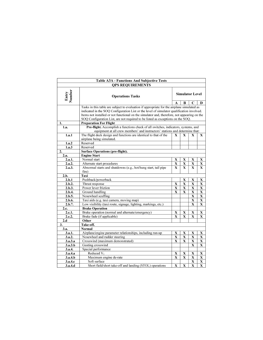
114
14 CFR Ch. I (1–1–24 Edition)
Pt. 60, App. A
VerDate Sep<11>2014
14:00 Mar 14, 2024
Jkt 262047
PO 00000
Frm 00124
Fmt 8010
Sfmt 8006
Q:\14\14V2.TXT
PC31
ER20MY16.050</GPH>
aworley on LAPBH6H6L3 with DISTILLER
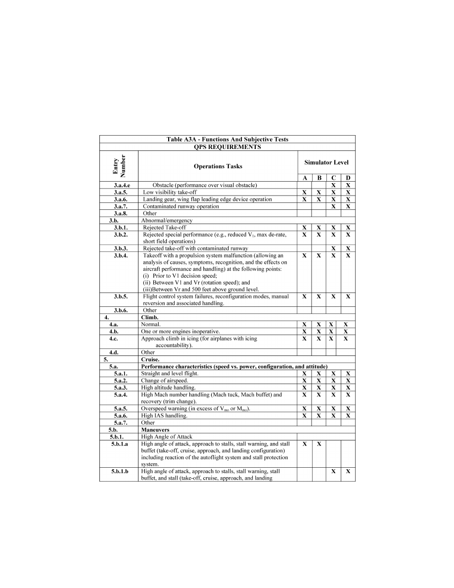
115
Federal Aviation Administration, DOT
Pt. 60, App. A
VerDate Sep<11>2014
14:00 Mar 14, 2024
Jkt 262047
PO 00000
Frm 00125
Fmt 8010
Sfmt 8006
Q:\14\14V2.TXT
PC31
ER20MY16.051</GPH>
aworley on LAPBH6H6L3 with DISTILLER
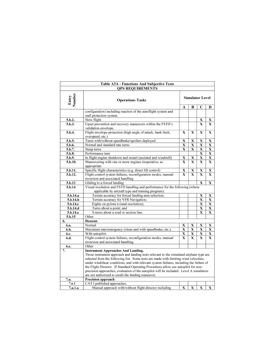
116
14 CFR Ch. I (1–1–24 Edition)
Pt. 60, App. A
VerDate Sep<11>2014
14:00 Mar 14, 2024
Jkt 262047
PO 00000
Frm 00126
Fmt 8010
Sfmt 8006
Q:\14\14V2.TXT
PC31
ER20MY16.052</GPH>
aworley on LAPBH6H6L3 with DISTILLER
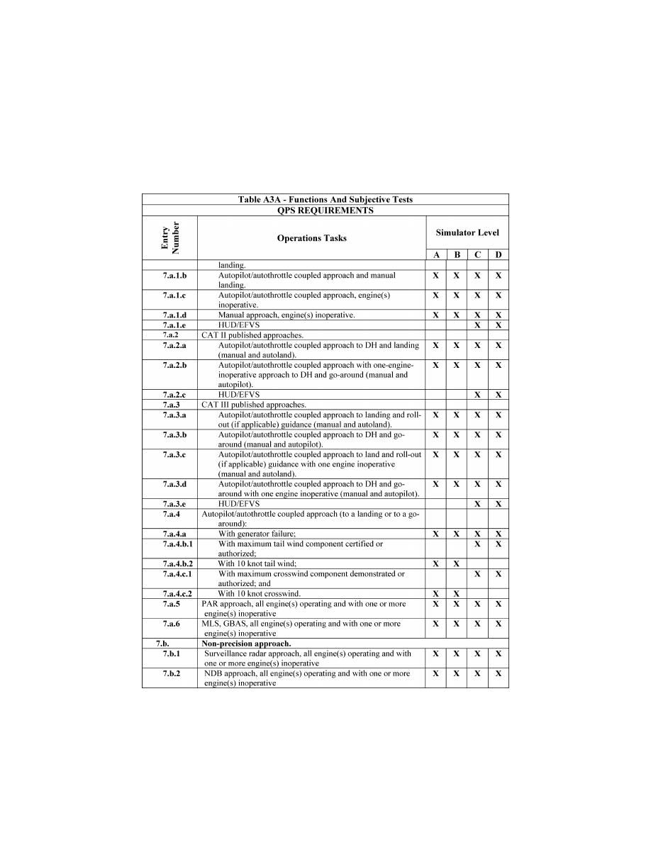
117
Federal Aviation Administration, DOT
Pt. 60, App. A
VerDate Sep<11>2014
14:00 Mar 14, 2024
Jkt 262047
PO 00000
Frm 00127
Fmt 8010
Sfmt 8006
Q:\14\14V2.TXT
PC31
ER20MY16.053</GPH>
aworley on LAPBH6H6L3 with DISTILLER
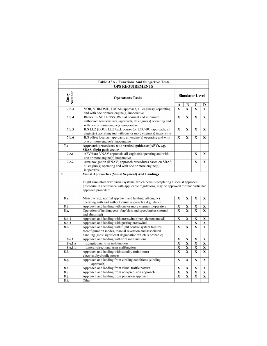
118
14 CFR Ch. I (1–1–24 Edition)
Pt. 60, App. A
VerDate Sep<11>2014
14:00 Mar 14, 2024
Jkt 262047
PO 00000
Frm 00128
Fmt 8010
Sfmt 8006
Q:\14\14V2.TXT
PC31
ER20MY16.054</GPH>
aworley on LAPBH6H6L3 with DISTILLER
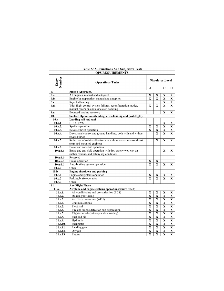
119
Federal Aviation Administration, DOT
Pt. 60, App. A
VerDate Sep<11>2014
14:00 Mar 14, 2024
Jkt 262047
PO 00000
Frm 00129
Fmt 8010
Sfmt 8006
Q:\14\14V2.TXT
PC31
ER20MY16.055</GPH>
aworley on LAPBH6H6L3 with DISTILLER
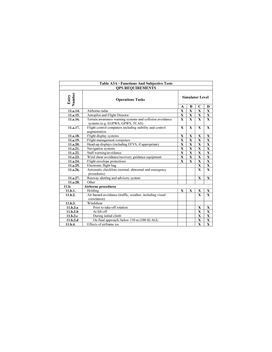
120
14 CFR Ch. I (1–1–24 Edition)
Pt. 60, App. A
VerDate Sep<11>2014
14:00 Mar 14, 2024
Jkt 262047
PO 00000
Frm 00130
Fmt 8010
Sfmt 8006
Q:\14\14V2.TXT
PC31
ER20MY16.056</GPH>
aworley on LAPBH6H6L3 with DISTILLER
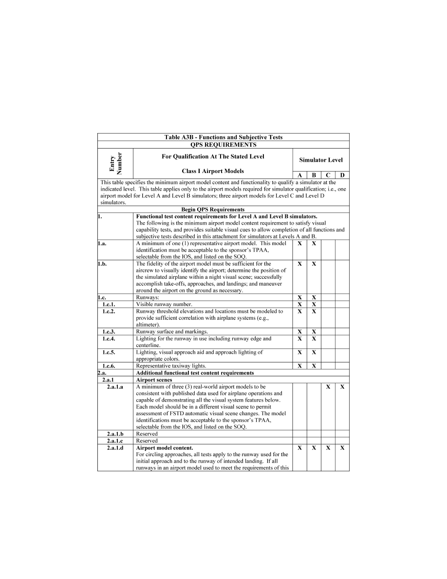
121
Federal Aviation Administration, DOT
Pt. 60, App. A
VerDate Sep<11>2014
14:00 Mar 14, 2024
Jkt 262047
PO 00000
Frm 00131
Fmt 8010
Sfmt 8006
Q:\14\14V2.TXT
PC31
ER20MY16.057</GPH>
aworley on LAPBH6H6L3 with DISTILLER
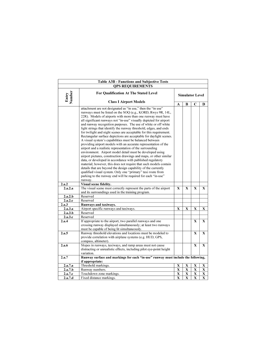
122
14 CFR Ch. I (1–1–24 Edition)
Pt. 60, App. A
VerDate Sep<11>2014
14:00 Mar 14, 2024
Jkt 262047
PO 00000
Frm 00132
Fmt 8010
Sfmt 8006
Q:\14\14V2.TXT
PC31
ER20MY16.058</GPH>
aworley on LAPBH6H6L3 with DISTILLER
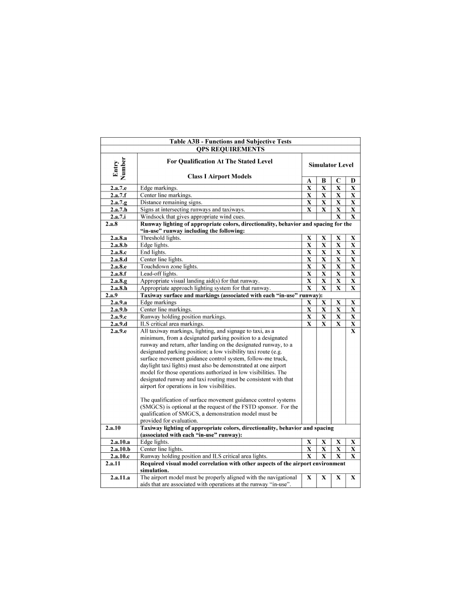
123
Federal Aviation Administration, DOT
Pt. 60, App. A
VerDate Sep<11>2014
14:00 Mar 14, 2024
Jkt 262047
PO 00000
Frm 00133
Fmt 8010
Sfmt 8006
Q:\14\14V2.TXT
PC31
ER20MY16.059</GPH>
aworley on LAPBH6H6L3 with DISTILLER
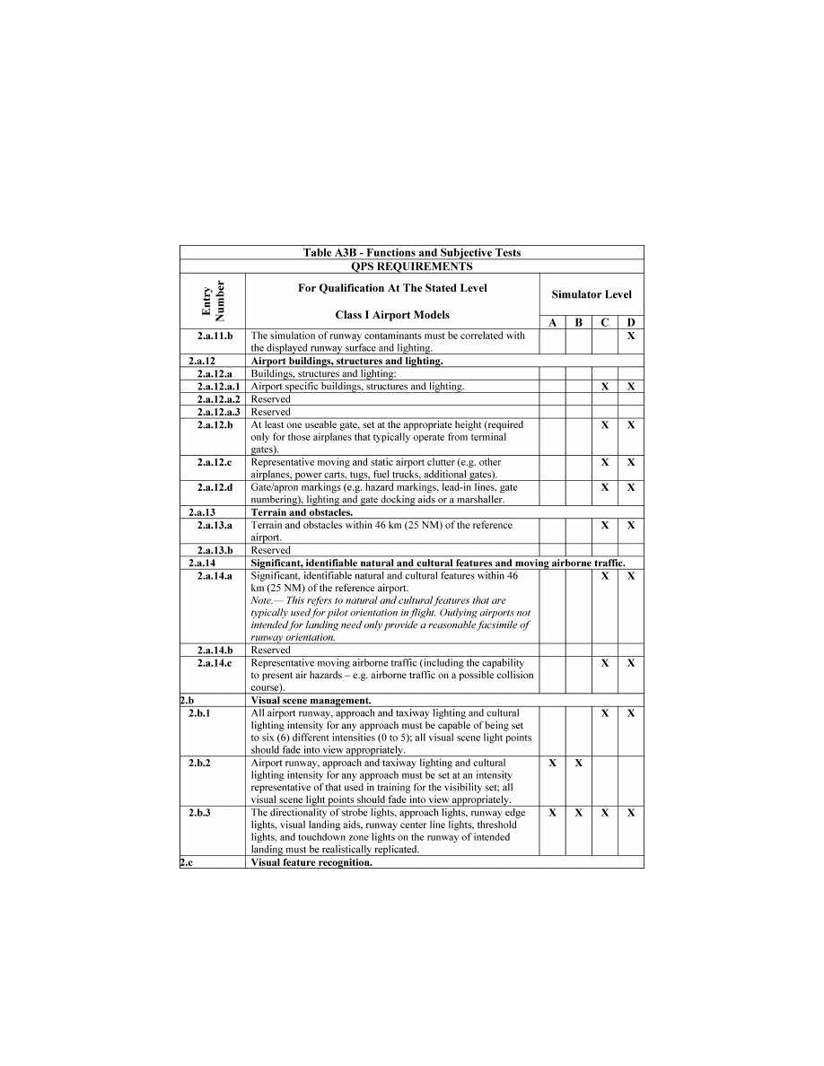
124
14 CFR Ch. I (1–1–24 Edition)
Pt. 60, App. A
VerDate Sep<11>2014
14:00 Mar 14, 2024
Jkt 262047
PO 00000
Frm 00134
Fmt 8010
Sfmt 8006
Q:\14\14V2.TXT
PC31
ER20MY16.060</GPH>
aworley on LAPBH6H6L3 with DISTILLER
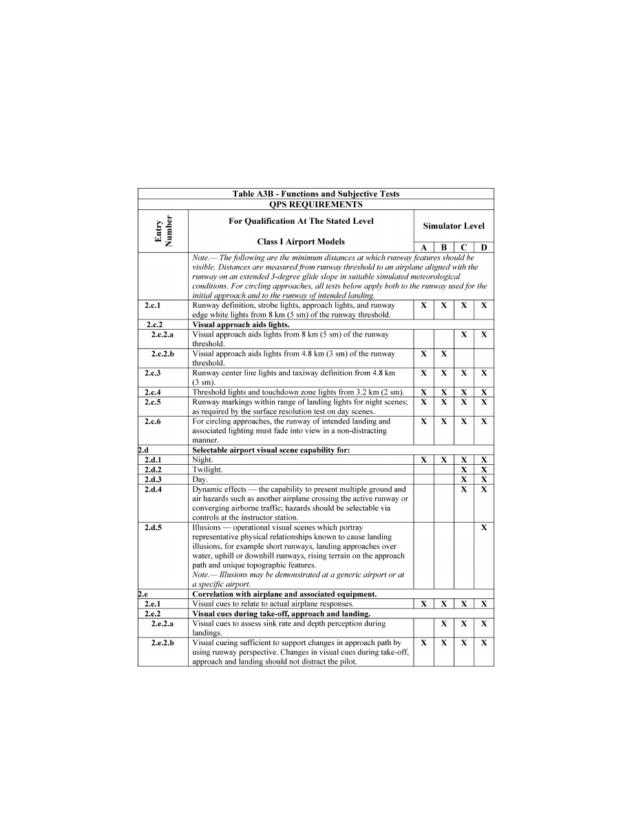
125
Federal Aviation Administration, DOT
Pt. 60, App. A
VerDate Sep<11>2014
14:00 Mar 14, 2024
Jkt 262047
PO 00000
Frm 00135
Fmt 8010
Sfmt 8006
Q:\14\14V2.TXT
PC31
ER20MY16.061</GPH>
aworley on LAPBH6H6L3 with DISTILLER
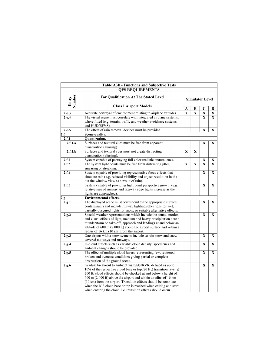
126
14 CFR Ch. I (1–1–24 Edition)
Pt. 60, App. A
VerDate Sep<11>2014
14:00 Mar 14, 2024
Jkt 262047
PO 00000
Frm 00136
Fmt 8010
Sfmt 8006
Q:\14\14V2.TXT
PC31
ER20MY16.062</GPH>
aworley on LAPBH6H6L3 with DISTILLER
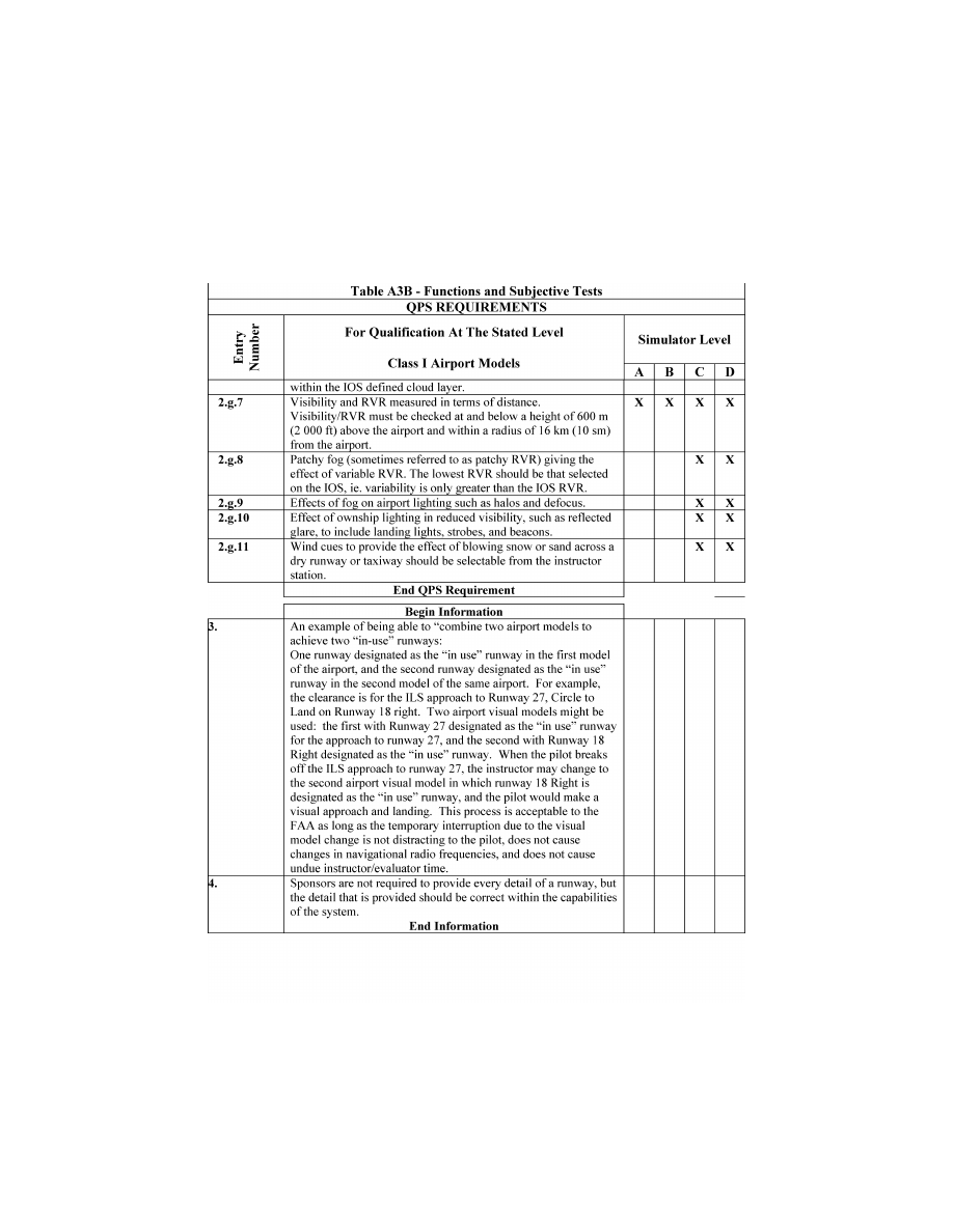
127
Federal Aviation Administration, DOT
Pt. 60, App. A
VerDate Sep<11>2014
14:00 Mar 14, 2024
Jkt 262047
PO 00000
Frm 00137
Fmt 8010
Sfmt 8006
Q:\14\14V2.TXT
PC31
ER20MY16.063</GPH>
aworley on LAPBH6H6L3 with DISTILLER

128
14 CFR Ch. I (1–1–24 Edition)
Pt. 60, App. A
T
ABLE
A3C—F
UNCTIONS AND
S
UBJECTIVE
T
ESTS
QPS requirements
Entry No.
Additional airport models beyond minimum required for qualification—Class II airport mod-
els
Simulator level
A B C D
This table specifies the minimum airport model content and functionality necessary to add airport models to a simulator’s model
library, beyond those necessary for qualification at the stated level, without the necessity of further involvement of the respon-
sible Flight Standards office or TPAA.
Begin QPS Requirements
1. ....................
Airport model management. The following is the minimum airport model management requirements for simula-
tors at Levels A, B, C, and D.
1.a. ..........
The direction of strobe lights, approach lights, runway edge lights, visual landing aids, run-
way centerline lights, threshold lights, and touchdown zone lights on the ‘‘in-use’’ runway
must be replicated.
X X X X
2. ....................
Visual feature recognition. The following are the minimum distances at which runway features must be visible
for simulators at Levels A, B, C, and D. Distances are measured from runway threshold to an airplane aligned
with the runway on an extended 3
°
glide-slope in simulated meteorological conditions that recreate the min-
imum distances for visibility. For circling approaches, all requirements of this section apply to the runway used
for the initial approach and to the runway of intended landing.
2.a. ..........
Runway definition, strobe lights, approach lights, and runway edge white lights from 5 sm
(8 km) from the runway threshold.
X X X X
2.b. ..........
Visual Approach Aid lights (VASI or PAPI) from 5 sm (8 km) from the runway threshold .....
X
X
2.c. ..........
Visual Approach Aid lights (VASI or PAPI) from 3 sm (5 km) from the runway threshold .....
X
X
2.d. ..........
Runway centerline lights and taxiway definition from 3 sm (5 km) from the runway thresh-
old.
X X X X
2.e. ..........
Threshold lights and touchdown zone lights from 2 sm (3 km) from the runway threshold ...
X
X
X
X
2.f. ...........
Runway markings within range of landing lights for night scenes and as required by the
surface resolution requirements on day scenes.
X X X X
2.g. ..........
For circling approaches, the runway of intended landing and associated lighting must fade
into view in a non-distracting manner.
X X X X
3. ....................
Airport model content. The following prescribes the minimum requirements for what must be provided in an air-
port model and identifies other aspects of the airport environment that must correspond with that model for sim-
ulators at Levels A, B, C, and D. The detail must be developed using airport pictures, construction drawings
and maps, or other similar data, or developed in accordance with published regulatory material; however, this
does not require that airport models contain details that are beyond the designed capability of the currently
qualified visual system. For circling approaches, all requirements of this section apply to the runway used for
the initial approach and to the runway of intended landing. Only one ‘‘primary’’ taxi route from parking to the
runway end will be required for each ‘‘in-use’’ runway.
3.a. ..........
The surface and markings for each ‘‘in-use’’ runway:
3.a.1. Threshold
markings ..................................................................................................................
X X X X
3.a.2. Runway
numbers ......................................................................................................................
X X X X
3.a.3.
Touchdown zone markings .......................................................................................................
X X X X
3.a.4.
Fixed distance markings ...........................................................................................................
X X X X
3.a.5. Edge
markings ..........................................................................................................................
X X X X
3.a.6. Centerline
stripes ......................................................................................................................
X X X X
3.b. ..........
The lighting for each ‘‘in-use’’ runway
3.b.1. Threshold
lights ........................................................................................................................
X X X X
3.b.2. Edge
lights ................................................................................................................................
X X X X
3.b.3. End
lights ..................................................................................................................................
X X X X
3.b.4. Centerline
lights ........................................................................................................................
X X X X
VerDate Sep<11>2014
14:00 Mar 14, 2024
Jkt 262047
PO 00000
Frm 00138
Fmt 8010
Sfmt 8002
Q:\14\14V2.TXT
PC31
aworley on LAPBH6H6L3 with DISTILLER

129
Federal Aviation Administration, DOT
Pt. 60, App. A
T
ABLE
A3C—F
UNCTIONS AND
S
UBJECTIVE
T
ESTS
—Continued
QPS requirements
Entry No.
Additional airport models beyond minimum required for qualification—Class II airport mod-
els
Simulator level
A B C D
3.b.5.
Touchdown zone lights, if appropriate .....................................................................................
X X X X
3.b.6.
Leadoff lights, if appropriate .....................................................................................................
X X X X
3.b.7.
Appropriate visual landing aid(s) for that runway .....................................................................
X
X X X
3.b.8.
Appropriate approach lighting system for that runway .............................................................
X
X
X
X
3.c. ..........
The taxiway surface and markings associated with each ‘‘in-use’’ runway:
3.c.1. Edge ..........................................................................................................................................
X X X X
3.c.2. Centerline ..................................................................................................................................
X X X X
3.c.3.
Runway hold lines ....................................................................................................................
X X X X
3.c.4.
ILS critical area markings .........................................................................................................
X X X X
3.d. ..........
The taxiway lighting associated with each ‘‘in-use’’ runway:
3.d.1. Edge ..........................................................................................................................................
X X
3.d.2. Centerline ..................................................................................................................................
X X X X
3.d.3.
Runway hold and ILS critical area lights ..................................................................................
X X X X
4. ....................
Required model correlation with other aspects of the airport environment simulation The
following are the minimum model correlation tests that must be conducted for simulators
at Levels A, B, C, and D.
4.a. ..........
The airport model must be properly aligned with the navigational aids that are associated
with operations at the ‘‘in-use’’ runway.
X X X X
4.b. ..........
Slopes in runways, taxiways, and ramp areas, if depicted in the visual scene, must not
cause distracting or unrealistic effects.
X X X X
5. ....................
Correlation with airplane and associated equipment. The following are the minimum correlation comparisons
that must be made for simulators at Levels A, B, C, and D.
5.a. .............
Visual system compatibility with aerodynamic programming ...................................................
X
X X X
5.b. ..........
Accurate portrayal of environment relating to flight simulator attitudes ...................................
X
X
X
X
5.c. ..........
Visual cues to assess sink rate and depth perception during landings ...................................
X
X
X
5.d. ..........
Visual effects for each visible, own-ship, airplane external light(s) .........................................
X
X X
6. ....................
Scene quality. The following are the minimum scene quality tests that must be conducted for simulators at Lev-
els A, B, C, and D.
6.a. ..........
Surfaces and textural cues must be free of apparent and distracting quantization (aliasing)
X
X
6.b. .................
Correct color and realistic textural cues ...................................................................................
X X
6.c. .................
Light points free from distracting jitter, smearing or streaking .................................................
X X X X
7. ....................
Instructor controls of the following: The following are the minimum instructor controls that must be available in
simulators at Levels A, B, C, and D.
7.a. ..........
Environmental effects, e.g., cloud base (if used), cloud effects, cloud density, visibility in
statute miles/kilometers and RVR in feet/meters.
X X X X
7.b. ..........
Airport selection ........................................................................................................................
X X X X
7.c. ..........
Airport lighting including variable intensity ...............................................................................
X X X X
7.d. ..........
Dynamic effects including ground and flight traffic ..................................................................
X X
VerDate Sep<11>2014
14:00 Mar 14, 2024
Jkt 262047
PO 00000
Frm 00139
Fmt 8010
Sfmt 8002
Q:\14\14V2.TXT
PC31
aworley on LAPBH6H6L3 with DISTILLER

130
14 CFR Ch. I (1–1–24 Edition)
Pt. 60, App. A
T
ABLE
A3C—F
UNCTIONS AND
S
UBJECTIVE
T
ESTS
—Continued
QPS requirements
Entry No.
Additional airport models beyond minimum required for qualification—Class II airport mod-
els
Simulator level
A B C D
End QPS Requirements
Begin Information
8. ....................
Sponsors are not required to provide every detail of a runway, but the detail that is pro-
vided must be correct within the capabilities of the system.
X X X X
End Information
VerDate Sep<11>2014
14:00 Mar 14, 2024
Jkt 262047
PO 00000
Frm 00140
Fmt 8010
Sfmt 8006
Q:\14\14V2.TXT
PC31
aworley on LAPBH6H6L3 with DISTILLER
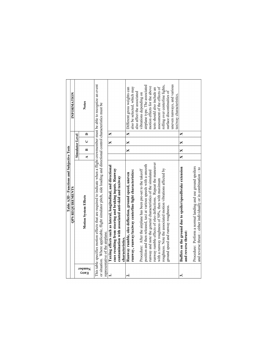
131
Federal Aviation Administration, DOT
Pt. 60, App. A
VerDate Sep<11>2014
14:00 Mar 14, 2024
Jkt 262047
PO 00000
Frm 00141
Fmt 8010
Sfmt 8006
Q:\14\14V2.TXT
PC31
ER20MY16.064</GPH>
aworley on LAPBH6H6L3 with DISTILLER
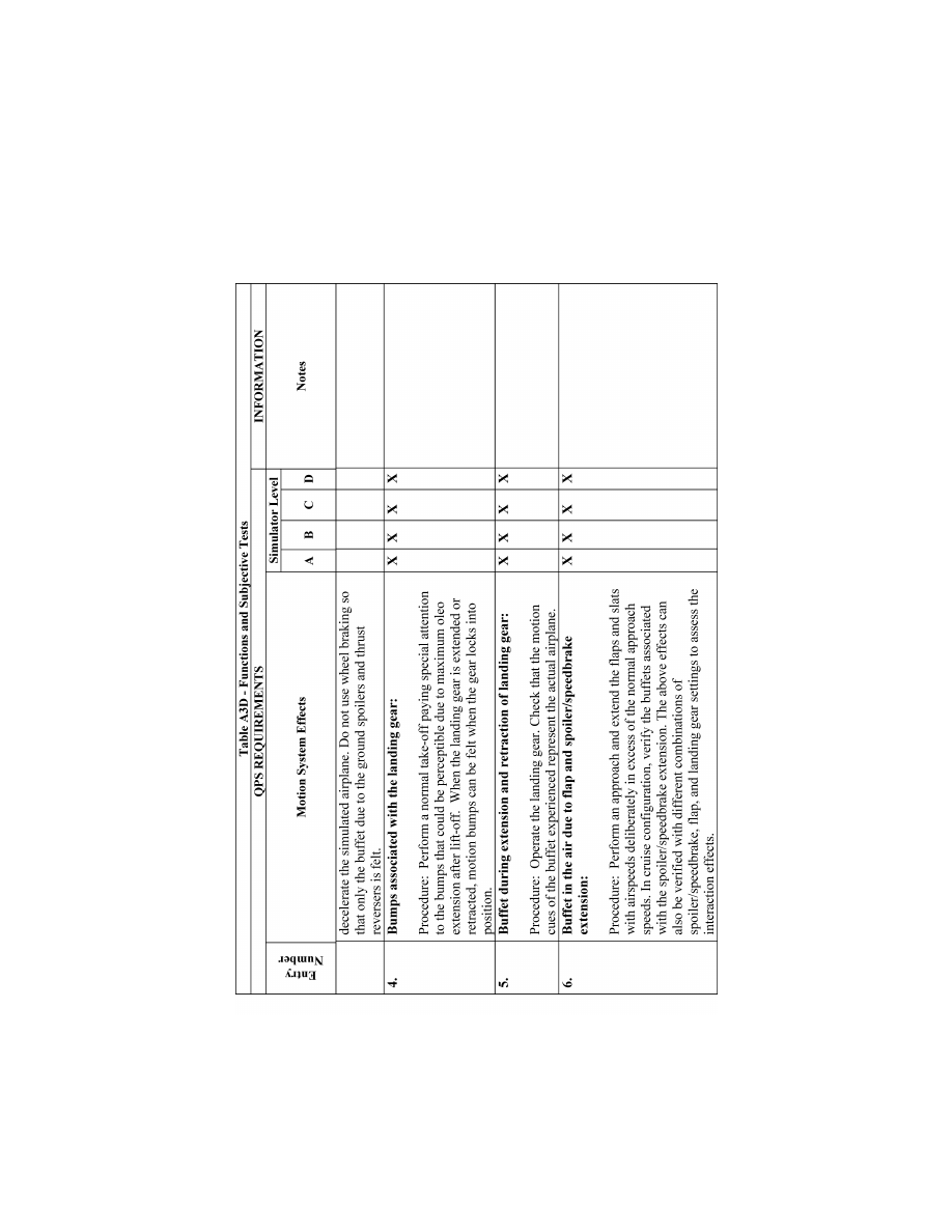
132
14 CFR Ch. I (1–1–24 Edition)
Pt. 60, App. A
VerDate Sep<11>2014
14:00 Mar 14, 2024
Jkt 262047
PO 00000
Frm 00142
Fmt 8010
Sfmt 8006
Q:\14\14V2.TXT
PC31
ER20MY16.065</GPH>
aworley on LAPBH6H6L3 with DISTILLER
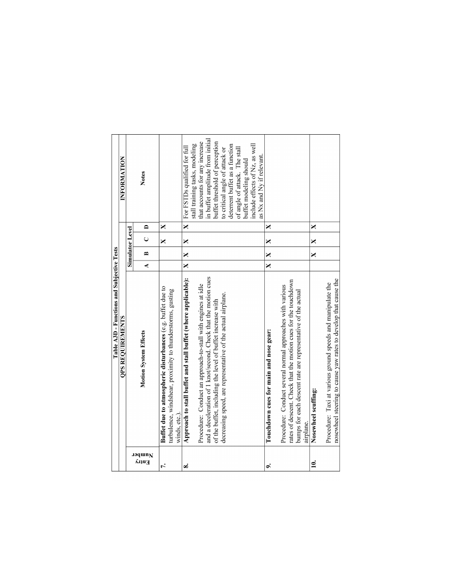
133
Federal Aviation Administration, DOT
Pt. 60, App. A
VerDate Sep<11>2014
14:00 Mar 14, 2024
Jkt 262047
PO 00000
Frm 00143
Fmt 8010
Sfmt 8006
Q:\14\14V2.TXT
PC31
ER20MY16.066</GPH>
aworley on LAPBH6H6L3 with DISTILLER
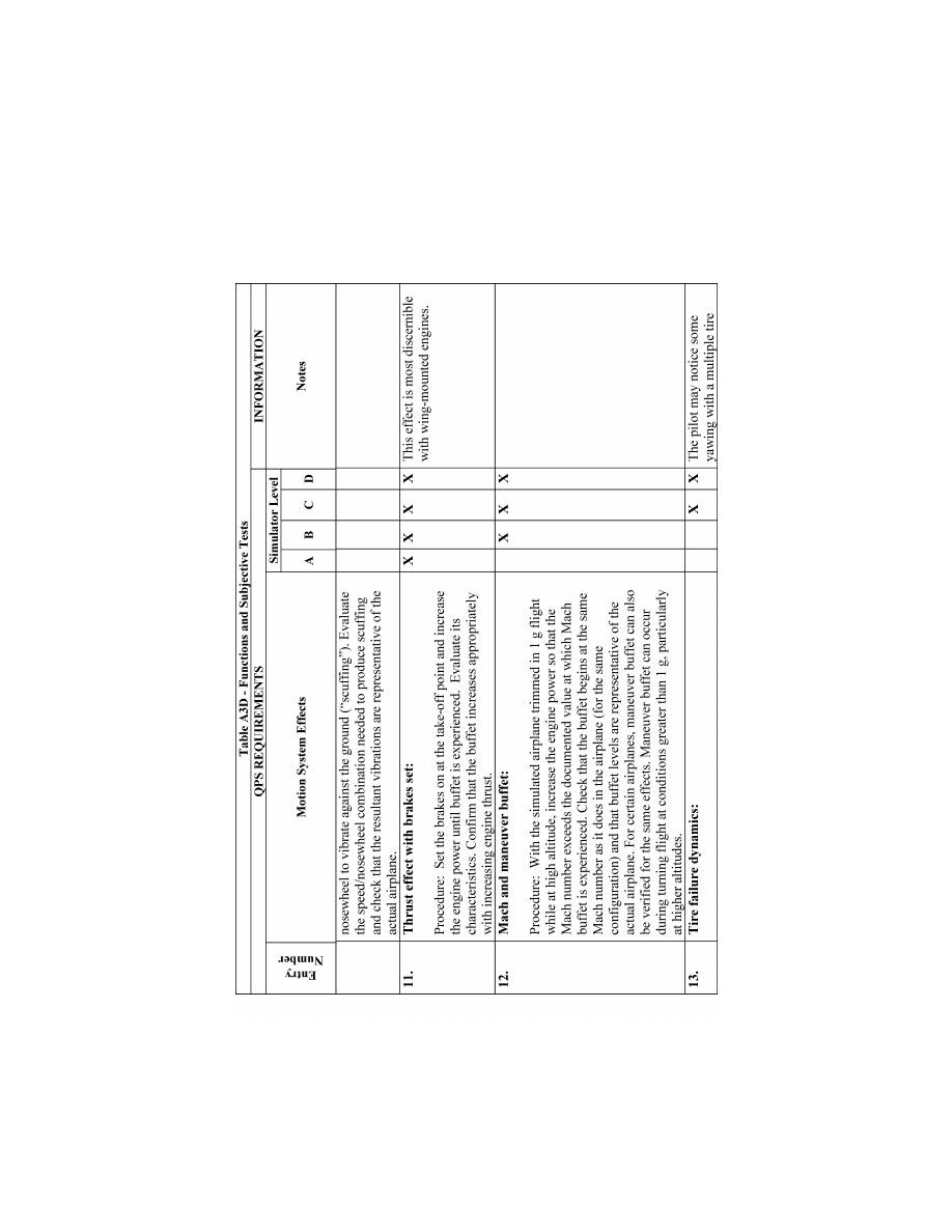
134
14 CFR Ch. I (1–1–24 Edition)
Pt. 60, App. A
VerDate Sep<11>2014
14:00 Mar 14, 2024
Jkt 262047
PO 00000
Frm 00144
Fmt 8010
Sfmt 8006
Q:\14\14V2.TXT
PC31
ER20MY16.067</GPH>
aworley on LAPBH6H6L3 with DISTILLER
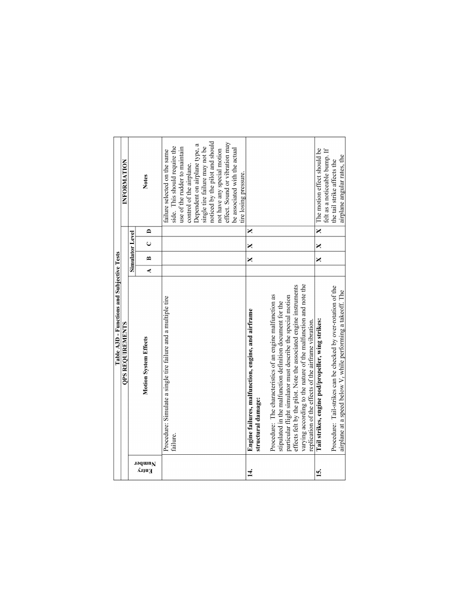
135
Federal Aviation Administration, DOT
Pt. 60, App. A
VerDate Sep<11>2014
14:00 Mar 14, 2024
Jkt 262047
PO 00000
Frm 00145
Fmt 8010
Sfmt 8006
Q:\14\14V2.TXT
PC31
ER20MY16.068</GPH>
aworley on LAPBH6H6L3 with DISTILLER
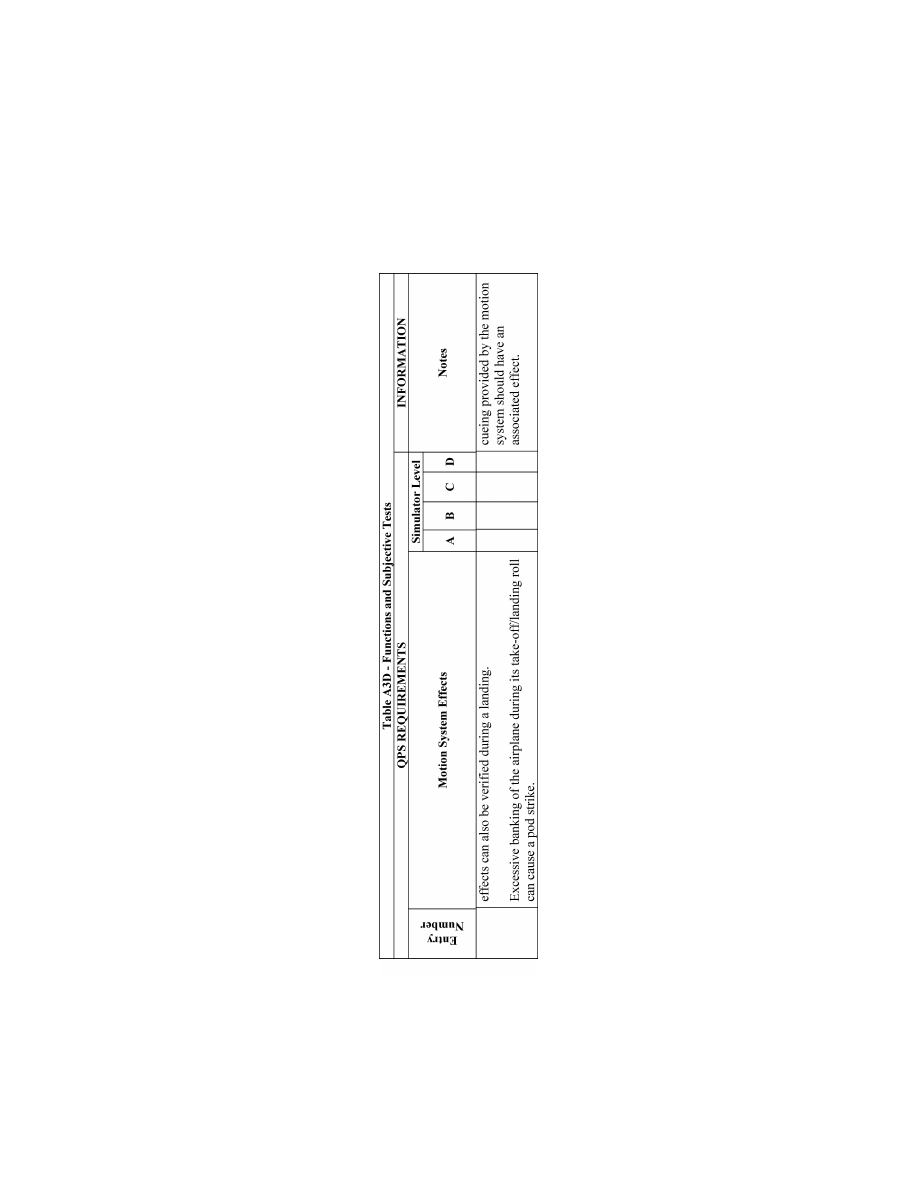
136
14 CFR Ch. I (1–1–24 Edition)
Pt. 60, App. A
VerDate Sep<11>2014
14:00 Mar 14, 2024
Jkt 262047
PO 00000
Frm 00146
Fmt 8010
Sfmt 8006
Q:\14\14V2.TXT
PC31
ER20MY16.069</GPH>
aworley on LAPBH6H6L3 with DISTILLER
137
Federal Aviation Administration, DOT
Pt. 60, App. A
T
ABLE
A3E—F
UNCTIONS AND
S
UBJECTIVE
T
ESTS
QPS Requirements
Entry No.
Sound system
Simulator level
A B C D
The following checks are performed during a normal flight profile with motion system ON.
1. ...............
Precipitation ....................................................................................................................................
X X
2. ...............
Rain removal equipment. ...............................................................................................................
X X
3. ...............
Significant airplane noises perceptible to the pilot during normal operations ...............................
X
X
4. ...............
Abnormal operations for which there are associated sound cues including, engine malfunc-
tions, landing gear/tire malfunctions, tail and engine pod strike and pressurization malfunc-
tion.
X X
5. ...............
Sound of a crash when the flight simulator is landed in excess of limitations .............................
X
X
VerDate Sep<11>2014
14:00 Mar 14, 2024
Jkt 262047
PO 00000
Frm 00147
Fmt 8010
Sfmt 8006
Q:\14\14V2.TXT
PC31
aworley on LAPBH6H6L3 with DISTILLER
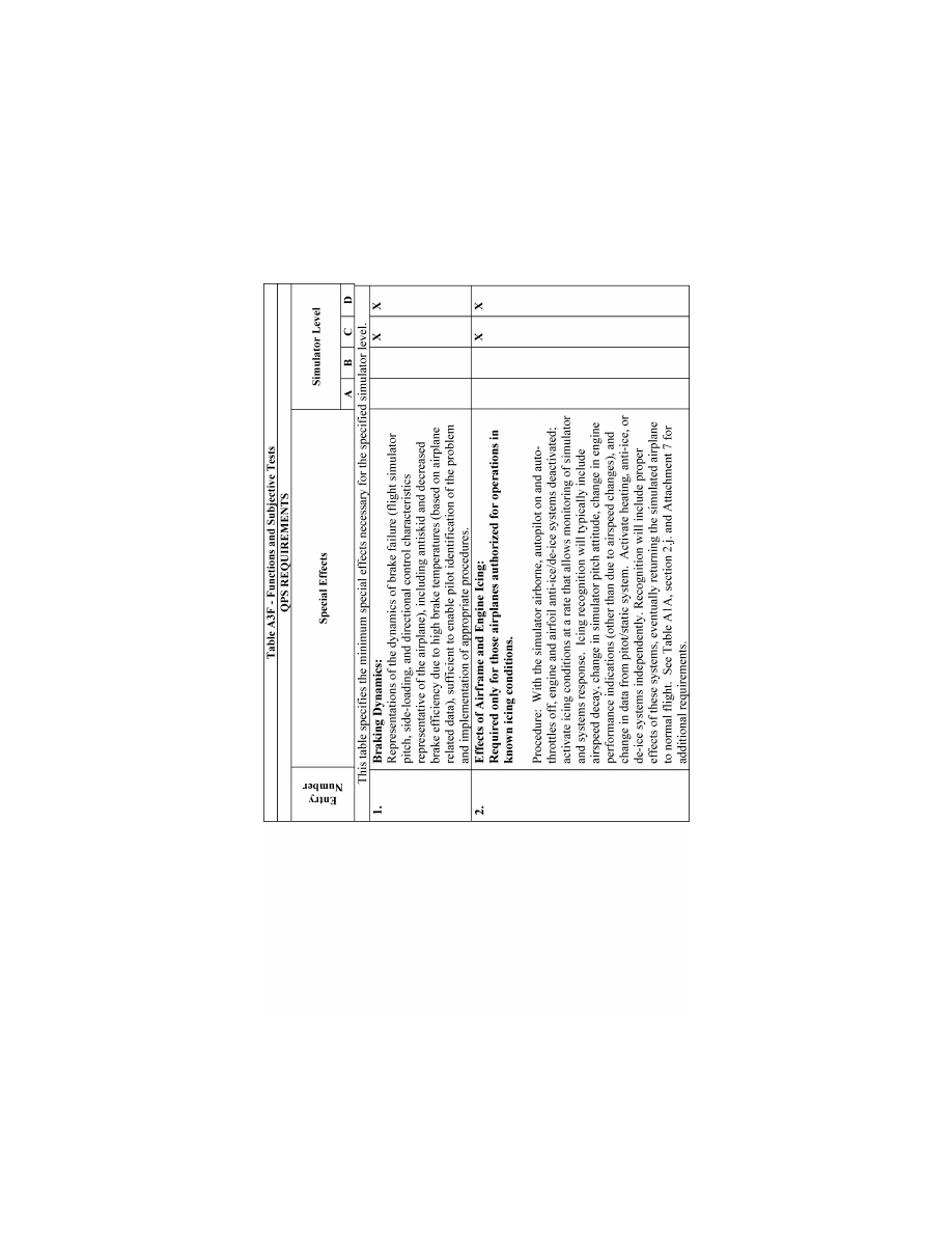
138
14 CFR Ch. I (1–1–24 Edition)
Pt. 60, App. A
VerDate Sep<11>2014
14:00 Mar 14, 2024
Jkt 262047
PO 00000
Frm 00148
Fmt 8010
Sfmt 8006
Q:\14\14V2.TXT
PC31
ER20MY16.070</GPH>
aworley on LAPBH6H6L3 with DISTILLER
139
Federal Aviation Administration, DOT
Pt. 60, App. A
T
ABLE
A3G—F
UNCTIONS AND
S
UBJECTIVE
T
ESTS
QPS Requirements
Entry No.
Special effects
Simulator level
A B C D
Functions in this table are subject to evaluation only if appropriate for the airplane and/or the system is installed on the specific
simulator.
1. ...............
Simulator Power Switch(es) ...........................................................................................................
X X X X
2. ...............
Airplane conditions
2.a. ....
Gross weight, center of gravity, fuel loading and allocation ..........................................................
X X X X
2.b. ....
Airplane systems status .................................................................................................................
X X X X
2.c. .....
Ground crew functions (e.g., ext. power, push back) ....................................................................
X X X X
3. ...............
Airports
3.a. ....
Number and selection ....................................................................................................................
X X X X
3.b. ....
Runway selection ...........................................................................................................................
X X X X
3.c. .....
Runway surface condition (e.g., rough, smooth, icy, wet) ............................................................
X
X
3.d. ....
Preset positions (e.g., ramp, gate, #1 for takeoff, takeoff position, over FAF) .............................
X
X
X
X
3.e. ....
Lighting controls .............................................................................................................................
X X X X
4. ...............
Environmental controls
4.a .....
Visibility (statute miles (kilometers)) ..............................................................................................
X X X X
4.b. ....
Runway visual range (in feet (meters)) .........................................................................................
X X X X
4.c. .....
Temperature ...................................................................................................................................
X X X X
4.d. ....
Climate conditions (e.g., ice, snow, rain) .......................................................................................
X X X X
4.e. ....
Wind speed and direction ..............................................................................................................
X X X X
4.f. .....
Windshear ......................................................................................................................................
X X
4.g. ....
Clouds (base and tops) ..................................................................................................................
X X X X
5. ...............
Airplane system malfunctions (Inserting and deleting malfunctions into the simulator) ...............
X
X
X
X
6. ...............
Locks, Freezes, and Repositioning
6.a. ....
Problem (all) freeze/release ...........................................................................................................
X X X X
6.b. ....
Position (geographic) freeze/release .............................................................................................
X X X X
6.c. .....
Repositioning (locations, freezes, and releases) ...........................................................................
X X X X
6.d. ....
Ground speed control ....................................................................................................................
X X X X
7. ...............
Remote IOS ...................................................................................................................................
X X X X
8. ...............
Sound Controls. On/off/adjustment ................................................................................................
X X X X
9. ...............
Motion/Control Loading System
9.a. ....
On/off/emergency stop ...................................................................................................................
X X X X
10. .............
Observer Seats/Stations. Position/Adjustment/Positive restraint system ......................................
X
X X X
VerDate Sep<11>2014
14:00 Mar 14, 2024
Jkt 262047
PO 00000
Frm 00149
Fmt 8010
Sfmt 8002
Q:\14\14V2.TXT
PC31
aworley on LAPBH6H6L3 with DISTILLER

140
14 CFR Ch. I (1–1–24 Edition)
Pt. 60, App. A
llllllllllllllllllllllll
B
EGIN
I
NFORMATION
1. I
NTRODUCTION
a. The following is an example test sched-
ule for an Initial/Upgrade evaluation that
covers the majority of the requirements set
out in the Functions and Subjective test re-
quirements. It is not intended that the
schedule be followed line by line, rather, the
example should be used as a guide for pre-
paring a schedule that is tailored to the air-
plane, sponsor, and training task.
b. Functions and subjective tests should be
planned. This information has been orga-
nized as a reference document with the con-
siderations, methods, and evaluation notes
for each individual aspect of the simulator
task presented as an individual item. In this
way the evaluator can design his or her own
test plan, using the appropriate sections to
provide guidance on method and evaluation
criteria. Two aspects should be present in
any test plan structure:
(1) An evaluation of the simulator to deter-
mine that it replicates the aircraft and per-
forms reliably for an uninterrupted period
equivalent to the length of a typical training
session.
(2) The simulator should be capable of op-
erating reliably after the use of training de-
vice functions such as repositions or mal-
functions.
c. A detailed understanding of the training
task will naturally lead to a list of objec-
tives that the simulator should meet. This
list will form the basis of the test plan. Addi-
tionally, once the test plan has been formu-
lated, the initial conditions and the evalua-
tion criteria should be established. The eval-
uator should consider all factors that may
have an influence on the characteristics ob-
served during particular training tasks in
order to make the test plan successful.
2. E
VENTS
a. Initial Conditions
(1) Airport.
(2) QNH.
(3) Temperature.
(4) Wind/Crosswind.
(5) Zero Fuel Weight /Fuel/Gross Weight
/Center of Gravity.
b. Initial Checks
(1) Documentation of Simulator.
(a) Simulator Acceptance Test Manuals.
(b) Simulator Approval Test Guide.
(c) Technical Logbook Open Item List.
(d) Daily Functional Pre-flight Check.
(2) Documentation of User/Carrier Flight
Logs.
(a) Simulator Operating/Instructor Man-
ual.
(b) Difference List (Aircraft/Simulator).
(c) Flight Crew Operating Manuals.
(d) Performance Data for Different Fields.
(e) Crew Training Manual.
(f) Normal/Abnormal/Emergency Check-
lists.
(3) Simulator External Checks.
(a) Appearance and Cleanliness.
(b) Stairway/Access Bridge.
(c) Emergency Rope Ladders.
(d) ‘‘Motion On’’/‘‘Flight in Progress’’
Lights.
(4) Simulator Internal Checks.
(a) Cleaning/Disinfecting Towels (for clean-
ing oxygen masks).
(b) Flight deck Layout (compare with dif-
ference list).
(5) Equipment.
(a) Quick Donning Oxygen Masks.
(b) Head Sets.
(c) Smoke Goggles.
(d) Sun Visors.
(e) Escape Rope.
(f) Chart Holders.
(g) Flashlights.
(h) Fire Extinguisher (inspection date).
(i) Crash Axe.
(j) Gear Pins.
c. Power Supply and APU Start Checks
(1) Batteries and Static Inverter.
(2) APU Start with Battery.
(3) APU Shutdown using Fire Handle.
(4) External Power Connection.
(5) APU Start with External Power.
(6) Abnormal APU Start/Operation.
d. Flight deck Checks
(1) Flight deck Preparation Checks.
(2) FMC Programming.
(3) Communications and Navigational Aids
Checks.
e. Engine Start
(1) Before Start Checks.
(2) Battery start with Ground Air Supply
Unit.
(3) Engine Crossbleed Start.
(4) Normal Engine Start.
(5) Abnormal Engine Starts.
(6) Engine Idle Readings.
(7) After Start Checks.
f. Taxi Checks
(1) Pushback/Powerback.
(2) Taxi Checks.
(3) Ground Handling Check:
(a) Power required to initiate ground roll.
(b) Thrust response.
(c) Nosewheel and Pedal Steering.
(d) Nosewheel Scuffing.
(e) Perform 180 degree turns.
(f) Brakes Response and Differential Brak-
ing using Normal, Alternate and Emergency.
(g) Brake Systems.
(h) Eye height and fore/aft position.
(4) Runway Roughness.
VerDate Sep<11>2014
14:00 Mar 14, 2024
Jkt 262047
PO 00000
Frm 00150
Fmt 8010
Sfmt 8002
Q:\14\14V2.TXT
PC31
aworley on LAPBH6H6L3 with DISTILLER

141
Federal Aviation Administration, DOT
Pt. 60, App. A
g. Visual Scene—Ground Assessment. Select 3
different airport models and perform the fol-
lowing checks with Day, Dusk and Night se-
lected, as appropriate:
(1) Visual Controls.
(a) Daylight, Dusk, Night Scene Controls.
(b) Flight deck ‘‘Daylight’’ ambient light-
ing.
(c) Environment Light Controls.
(d) Runway Light Controls.
(e) Taxiway Light Controls.
(2) Airport Model Content.
(a) Ramp area for buildings, gates,
airbridges, maintenance ground equipment,
parked aircraft.
(b) Daylight shadows, night time light
pools.
(c) Taxiways for correct markings, taxi-
way/runway, marker boards, CAT I and II/III
hold points, taxiway shape/grass areas, taxi-
way light (positions and colors).
(d) Runways for correct markings, lead-off
lights, boards, runway slope, runway light
positions, and colors, directionality of run-
way lights.
(e) Airport environment for correct terrain
and significant features.
(f) Visual scene quantization (aliasing),
color, and occulting levels.
(3) Ground Traffic Selection.
(4) Environment Effects.
(a) Low cloud scene.
(i) Rain:
(A) Runway surface scene.
(B) Windshield wiper—operation and sound.
(ii) Hail:
(A) Runway surface scene.
(B) Windshield wiper—operation and sound.
(b) Lightning/thunder.
(c) Snow/ice runway surface scene.
(d) Fog.
h. Takeoff. Select one or several of the fol-
lowing test cases:
(1) T/O Configuration Warnings.
(2) Engine Takeoff Readings.
(3) Rejected Takeoff (Dry/Wet/Icy Runway)
and check the following:
(a) Autobrake function.
(b) Anti-skid operation.
(c) Motion/visual effects during decelera-
tion.
(d) Record stopping distance (use runway
plot or runway lights remaining).
Continue taxiing along the runway while
applying brakes and check the following:
(e) Center line lights alternating red/white
for 2000 feet/600 meters.
(f) Center line lights all red for 1000 feet/300
meters.
(g) Runway end, red stop bars.
(h) Braking fade effect.
(i) Brake temperature indications.
(4) Engine Failure between VI and V2.
(5) Normal Takeoff:
(a) During ground roll check the following:
(i) Runway rumble.
(ii) Acceleration cues.
(iii) Groundspeed effects.
(iv) Engine sounds.
(v) Nosewheel and rudder pedal steering.
(b) During and after rotation, check the
following:
(i) Rotation characteristics.
(ii) Column force during rotation.
(iii) Gear uplock sounds/bumps.
(iv) Effect of slat/flap retraction during
climbout.
(6) Crosswind Takeoff (check the fol-
lowing):
(a) Tendency to turn into or out of the
wind.
(b) Tendency to lift upwind wing as air-
speed increases.
(7) Windshear during Takeoff (check the
following):
(a) Controllable during windshear encoun-
ter.
(b) Performance adequate when using cor-
rect techniques.
(c) Windshear Indications satisfactory.
(d) Motion cues satisfactory (particularly
turbulence).
(8) Normal Takeoff with Control Malfunc-
tion.
(9) Low Visibility T/O (check the fol-
lowing):
(a) Visual cues.
(b) Flying by reference to instruments.
(c) SID Guidance on LNAV.
i. Climb Performance. Select one or several
of the following test cases:
(1) Normal Climb—Climb while maintain-
ing recommended speed profile and note fuel,
distance and time.
(2) Single Engine Climb—Trim aircraft in a
zero wheel climb at V2.
N
OTE
: Up to 5
°
bank towards the operating
engine(s) is permissible. Climb for 3 minutes
and note fuel, distance, and time. Increase
speed toward en route climb speed and re-
tract flaps. Climb for 3 minutes and note
fuel, distance, and time.
j. Systems Operation During Climb.
Check normal operation and malfunctions
as appropriate for the following systems:
(1) Air conditioning/Pressurization/Ven-
tilation.
(2) Autoflight.
(3) Communications.
(4) Electrical.
(5) Fuel.
(6) Icing Systems.
(7) Indicating and Recording Systems.
(8) Navigation/FMS.
(9) Pneumatics.
k. Cruise Checks. Select one or several of
the following test cases:
(1) Cruise Performance.
(2) High Speed/High Altitude Handling
(check the following):
(a) Overspeed warning.
(b) High Speed buffet.
(c) Aircraft control satisfactory.
VerDate Sep<11>2014
14:00 Mar 14, 2024
Jkt 262047
PO 00000
Frm 00151
Fmt 8010
Sfmt 8002
Q:\14\14V2.TXT
PC31
aworley on LAPBH6H6L3 with DISTILLER

142
14 CFR Ch. I (1–1–24 Edition)
Pt. 60, App. A
(d) Envelope limiting functions on Com-
puter Controlled Aircraft.
Reduce airspeed to below level flight buffet
onset speed, start a turn, and check the fol-
lowing:
(e) High Speed buffet increases with G
loading.
Reduce throttles to idle and start descent,
deploy the speedbrake, and check the fol-
lowing:
(f) Speedbrake indications.
(g) Symmetrical deployment.
(h) Airframe buffet.
(i) Aircraft response hands off.
(3) Yaw Damper Operation. Switch off yaw
dampers and autopilot. Initiate a Dutch roll
and check the following:
(a) Aircraft dynamics.
(b) Simulator motion effects.
Switch on yaw dampers, re-initiate a
Dutch roll and check the following:
(c) Damped aircraft dynamics.
(4) APU Operation.
(5) Engine Gravity Feed.
(6) Engine Shutdown and Driftdown Check:
FMC operation Aircraft performance.
(7) Engine Relight.
l. Descent. Select one of the following test
cases:
(1) Normal Descent. Descend while main-
taining recommended speed profile and note
fuel, distance and time.
(2) Cabin Depressurization/Emergency De-
scent.
m. Medium Altitude Checks. Select one or
several of the following test cases:
(1) High Angle of Attack/Stall. Trim the
aircraft at 1.4 Vs, establish 1 kt/sec
2
decel-
eration rate, and check the following—
(a) System displays/operation satisfactory.
(b) Handling characteristics satisfactory.
(c) Stall and Stick shaker speed.
(d) Buffet characteristics and onset speed.
(e) Envelope limiting functions on Com-
puter Controlled Aircraft.
Recover to straight and level flight and
check the following:
(f) Handling characteristics satisfactory.
(2) Turning Flight. Roll aircraft to left, es-
tablish a 30
°
to 45
°
bank angle, and check the
following:
(a) Stick force required, satisfactory.
(b) Wheel requirement to maintain bank
angle.
(c) Slip ball response, satisfactory.
(d) Time to turn 180
°
.
Roll aircraft from 45
°
bank one way to 45
°
bank the opposite direction while maintain-
ing altitude and airspeed—check the fol-
lowing:
(e) Controllability during maneuver.
(3) Degraded flight controls.
(4) Holding Procedure (check the fol-
lowing:)
(a) FMC operation.
(b) Autopilot auto thrust performance.
(5) Storm Selection (check the following:)
(a) Weather radar controls.
(b) Weather radar operation.
(c) Visual scene corresponds with WXR
pattern.
(Fly through storm center, and check the
following:)
(d) Aircraft enters cloud.
(e) Aircraft encounters representative tur-
bulence.
(f) Rain/hail sound effects evident.
As aircraft leaves storm area, check the fol-
lowing:
(g) Storm effects disappear.
(6) TCAS (check the following:)
(a) Traffic appears on visual display.
(b) Traffic appears on TCAS display(s).
As conflicting traffic approaches, take rel-
evant avoiding action, and check the fol-
lowing:
(c) Visual and TCAS system displays.
n. Approach and Landing. Select one or sev-
eral of the following test cases while moni-
toring flight control and hydraulic systems
for normal operation and with malfunctions
selected:
(1) Flaps/Gear Normal Operation. Check
the following:
(a) Time for extension/retraction.
(b) Buffet characteristics.
(2) Normal Visual Approach and Landing.
Fly a normal visual approach and land-
ing—check the following:
(a) Aircraft handling.
(b) Spoiler operation.
(c) Reverse thrust operation.
(d) Directional control on the ground.
(e) Touchdown cues for main and
nosewheel.
(f) Visual cues.
(g) Motion cues.
(h) Sound cues.
(i) Brake and anti-skid operation.
(3) Flaps/Gear Abnormal Operation or with
hydraulic malfunctions.
(4) Abnormal Wing Flaps/Slats Landing.
(5) Manual Landing with Control Malfunc-
tion.
(a) Aircraft handling.
(b) Radio aids and instruments.
(c) Airport model content and cues.
(d) Motion cues.
(e) Sound cues.
(6) Non-precision Approach—All Engines
Operating.
(a) Aircraft handling.
(b) Radio Aids and instruments.
(c) Airport model content and cues.
(d) Motion cues.
(e) Sound cues.
(7) Circling Approach.
(a) Aircraft handling.
(c) Radio Aids and instruments.
(d) Airport model content and cues.
(e) Motion cues.
(f) Sound cues.
(8) Non-precision Approach—One Engine
Inoperative.
VerDate Sep<11>2014
14:00 Mar 14, 2024
Jkt 262047
PO 00000
Frm 00152
Fmt 8010
Sfmt 8002
Q:\14\14V2.TXT
PC31
aworley on LAPBH6H6L3 with DISTILLER

143
Federal Aviation Administration, DOT
Pt. 60, App. A
(a) Aircraft handling.
(b) Radio Aids and instruments.
(c) Airport model content and cues.
(d) Motion cues.
(e) Sound cues.
(9) One Engine Inoperative Go-around.
(a) Aircraft handling.
(b) Radio Aids and instruments.
(c) Airport model content and cues.
(d) Motion cues.
(e) Sound cues.
(10) CAT I Approach and Landing with raw-
data ILS.
(a) Aircraft handling.
(b) Radio Aids and instruments.
(c) Airport model content and cues.
(d) Motion cues.
(e) Sound cues.
(11) CAT I Approach and Landing with
Limiting Crosswind.
(a) Aircraft handling.
(b) Radio Aids and instruments.
(c) Airport model content and cues.
(d) Motion cues.
(e) Sound cues.
(12) CAT I Approach with Windshear.
Check the following:
(a) Controllable during windshear encoun-
ter.
(b) Performance adequate when using cor-
rect techniques.
(c) Windshear indications/warnings.
(d) Motion cues (particularly turbulence).
(13) CAT II Approach and Automatic Go-
Around.
(14) CAT III Approach and Landing—Sys-
tem Malfunctions.
(15) CAT III Approach and Landing—1 En-
gine Inoperative.
(16) GPWS evaluation.
o. Visual Scene—In-Flight Assessment.
Select three (3) different visual models and
perform the following checks with ‘‘day,’’
‘‘dusk,’’ and ‘‘night’’ (as appropriate) se-
lected. Reposition the aircraft at or below
2000 feet within 10 nm of the airfield. Fly the
aircraft around the airport environment and
assess control of the visual system and
evaluate the Airport model content as de-
scribed below:
(1) Visual Controls.
(a) Daylight, Dusk, Night Scene Controls.
(b) Environment Light Controls.
(c) Runway Light Controls.
(d) Taxiway Light Controls.
(e) Approach Light Controls.
(2) Airport model Content.
(a) Airport environment for correct terrain
and significant features.
(b) Runways for correct markings, runway
slope, directionality of runway lights.
(c) Visual scene for quantization (aliasing),
color, and occulting.
Reposition the aircraft to a long, final ap-
proach for an ‘‘ILS runway.’’ Select flight
freeze when the aircraft is 5-statute miles
(sm)/8-kilometers (km) out and on the glide
slope. Check the following:
(3) Airport model content.
(a) Airfield features.
(b) Approach lights.
(c) Runway definition.
(d) Runway definition.
(e) Runway edge lights and VASI lights.
(f) Strobe lights.
Release flight freeze. Continue flying the
approach with NP engaged. Select flight
freeze when aircraft is 3 sm/5 km out and on
the glide slope. Check the following:
(4) Airport model Content.
(a) Runway centerline light.
(b) Taxiway definition and lights.
Release flight freeze and continue flying
the approach with A/P engaged. Select flight
freeze when aircraft is 2 sm/3 km out and on
the glide slope. Check the following:
(5) Airport model content.
(a) Runway threshold lights.
(b) Touchdown zone lights.
At 200 ft radio altitude and still on glide
slope, select Flight Freeze. Check the fol-
lowing:
(6) Airport model content.
(a) Runway markings.
Set the weather to Category I conditions
and check the following:
(7) Airport model content.
(a) Visual ground segment.
Set the weather to Category II conditions,
release Flight Freeze, re-select Flight Freeze
at 100 feet radio altitude, and check the fol-
lowing:
(8) Airport model content.
(a) Visual ground segment.
Select night/dusk (twilight) conditions and
check the following:
(9) Airport model content.
(a) Runway markings visible within land-
ing light lobes.
Set the weather to Category III conditions,
release Flight Freeze, re-select Flight Freeze
at 50 feet radio altitude and check the fol-
lowing:
(10) Airport model content.
(a) Visual ground segment.
Set WX to a typical ‘‘missed approach?
weather condition, release Flight Freeze, re-
select Flight Freeze at 15 feet radio altitude,
and check the following:
(11) Airport model content.
(a) Visual ground segment.
When on the ground, stop the aircraft. Set
0 feet RVR, ensure strobe/beacon tights are
switched on and check the following:
(12) Airport model content.
(a) Visual effect of strobe and beacon.
Reposition to final approach, set weather
to ‘‘Clear,’’ continue approach for an auto-
matic landing, and check the following:
(13) Airport model content.
(a) Visual cues during flare to assess sink
rate.
VerDate Sep<11>2014
14:00 Mar 14, 2024
Jkt 262047
PO 00000
Frm 00153
Fmt 8010
Sfmt 8002
Q:\14\14V2.TXT
PC31
aworley on LAPBH6H6L3 with DISTILLER
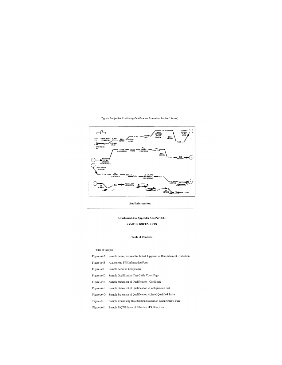
144
14 CFR Ch. I (1–1–24 Edition)
Pt. 60, App. A
(b) Visual cues during flare to assess Depth
perception.
(c) Flight deck height above ground.
After Landing Operations.
(1) After Landing Checks.
(2) Taxi back to gate. Check the following:
(a) Visual model satisfactory.
(b) Parking brake operation satisfactory.
(3) Shutdown Checks.
q. Crash Function.
(1) Gear-up Crash.
(2) Excessive rate of descent Crash.
(3) Excessive bank angle Crash.
VerDate Sep<11>2014
14:00 Mar 14, 2024
Jkt 262047
PO 00000
Frm 00154
Fmt 8010
Sfmt 8006
Q:\14\14V2.TXT
PC31
ER09MY08.005</GPH>
aworley on LAPBH6H6L3 with DISTILLER
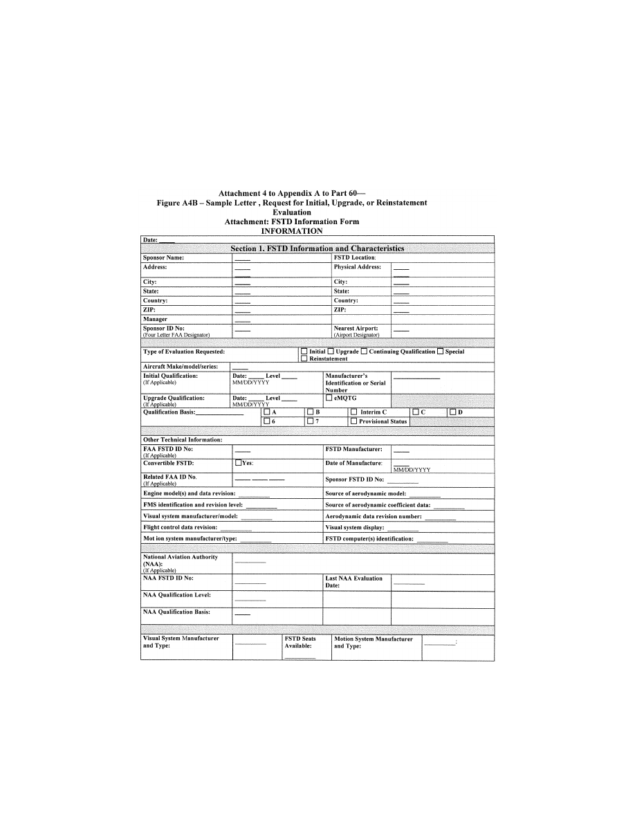
145
Federal Aviation Administration, DOT
Pt. 60, App. A
VerDate Sep<11>2014
14:00 Mar 14, 2024
Jkt 262047
PO 00000
Frm 00155
Fmt 8010
Sfmt 8006
Q:\14\14V2.TXT
PC31
ER09MY08.008</GPH>
aworley on LAPBH6H6L3 with DISTILLER
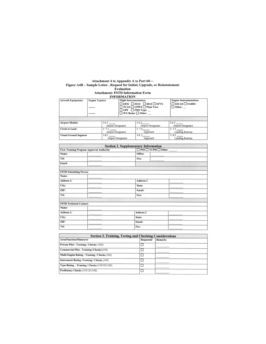
146
14 CFR Ch. I (1–1–24 Edition)
Pt. 60, App. A
VerDate Sep<11>2014
14:00 Mar 14, 2024
Jkt 262047
PO 00000
Frm 00156
Fmt 8010
Sfmt 8006
Q:\14\14V2.TXT
PC31
ER09MY08.009</GPH>
aworley on LAPBH6H6L3 with DISTILLER
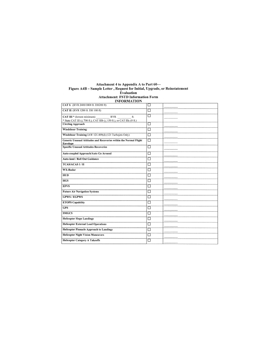
147
Federal Aviation Administration, DOT
Pt. 60, App. A
VerDate Sep<11>2014
14:00 Mar 14, 2024
Jkt 262047
PO 00000
Frm 00157
Fmt 8010
Sfmt 8006
Q:\14\14V2.TXT
PC31
ER09MY08.010</GPH>
aworley on LAPBH6H6L3 with DISTILLER
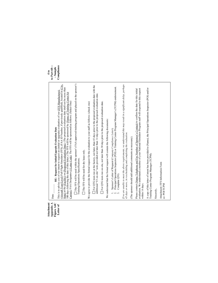
148
14 CFR Ch. I (1–1–24 Edition)
Pt. 60, App. A
VerDate Sep<11>2014
14:00 Mar 14, 2024
Jkt 262047
PO 00000
Frm 00158
Fmt 8010
Sfmt 8006
Q:\14\14V2.TXT
PC31
ER09DE22.054</GPH>
aworley on LAPBH6H6L3 with DISTILLER

149
Federal Aviation Administration, DOT
Pt. 60, App. A
A
TTACHMENT
4
TO
A
PPENDIX
A
TO
P
ART
60—
F
IGURE
A4D—S
AMPLE
Q
UALIFICATION
T
EST
G
UIDE
C
OVER
P
AGE
INFORMATION
VerDate Sep<11>2014
14:00 Mar 14, 2024
Jkt 262047
PO 00000
Frm 00159
Fmt 8010
Sfmt 8002
Q:\14\14V2.TXT
PC31
ER09DE22.055</GPH>
aworley on LAPBH6H6L3 with DISTILLER
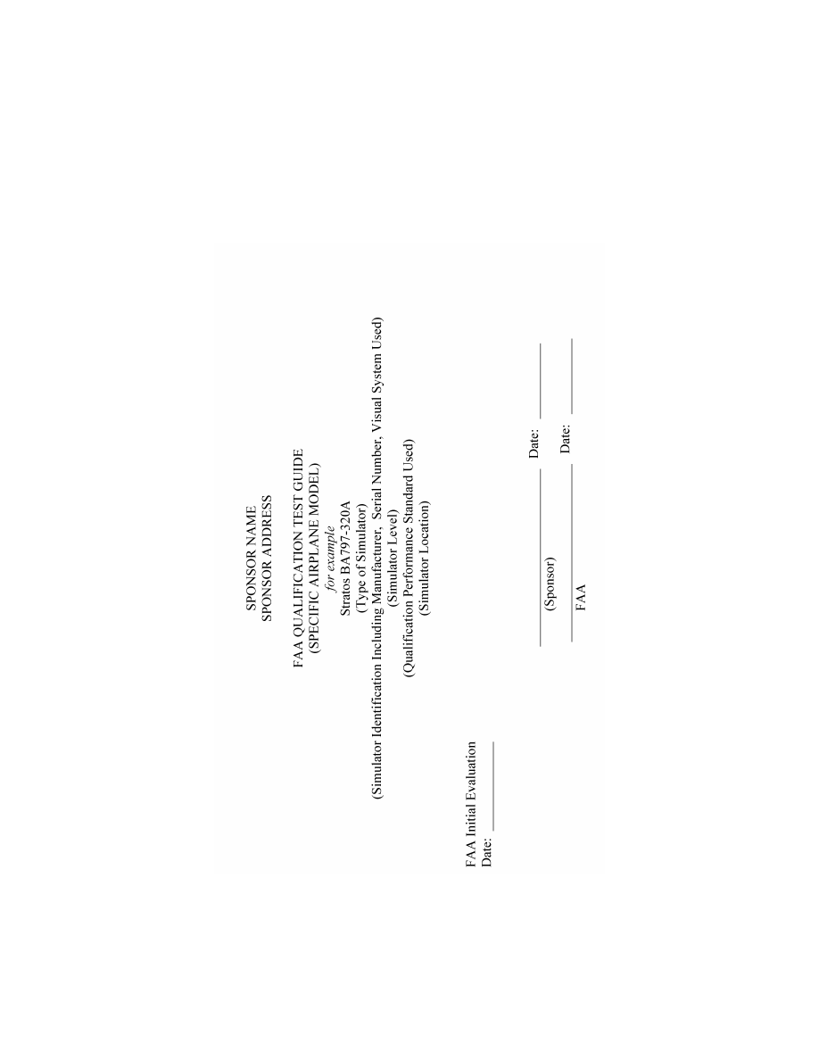
150
14 CFR Ch. I (1–1–24 Edition)
Pt. 60, App. A
VerDate Sep<11>2014
14:00 Mar 14, 2024
Jkt 262047
PO 00000
Frm 00160
Fmt 8010
Sfmt 8006
Q:\14\14V2.TXT
PC31
ER09DE22.056</GPH>
aworley on LAPBH6H6L3 with DISTILLER

151
Federal Aviation Administration, DOT
Pt. 60, App. A
A
TTACHMENT
4
TO
A
PPENDIX
A
TO
P
ART
60—
F
IGURE
A4E—S
AMPLE
S
TATEMENT OF
Q
UALI
-
FICATION
—C
ERTIFICATE
INFORMATION
VerDate Sep<11>2014
14:00 Mar 14, 2024
Jkt 262047
PO 00000
Frm 00161
Fmt 8010
Sfmt 8006
Q:\14\14V2.TXT
PC31
ER09DE22.127</GPH>
aworley on LAPBH6H6L3 with DISTILLER
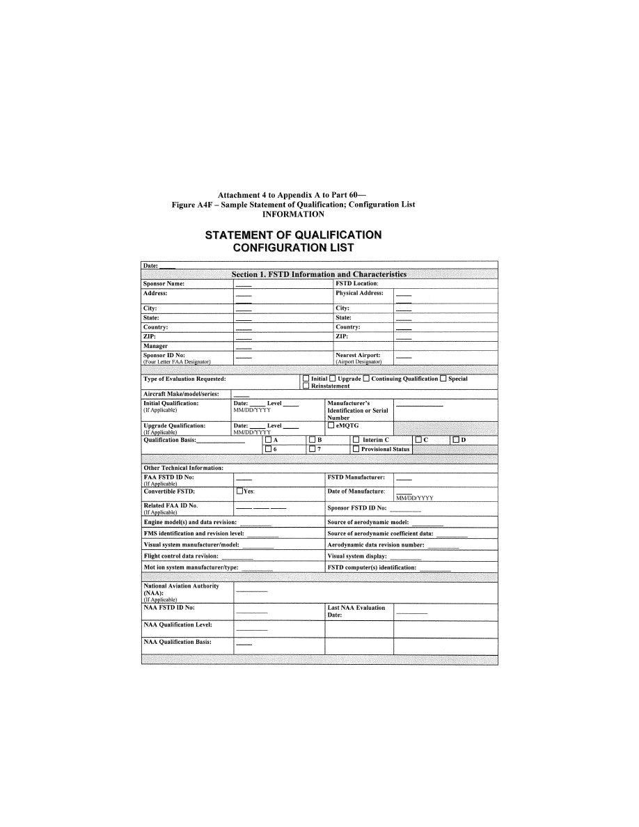
152
14 CFR Ch. I (1–1–24 Edition)
Pt. 60, App. A
VerDate Sep<11>2014
14:00 Mar 14, 2024
Jkt 262047
PO 00000
Frm 00162
Fmt 8010
Sfmt 8006
Q:\14\14V2.TXT
PC31
ER09MY08.014</GPH>
aworley on LAPBH6H6L3 with DISTILLER

153
Federal Aviation Administration, DOT
Pt. 60, App. A
VerDate Sep<11>2014
14:00 Mar 14, 2024
Jkt 262047
PO 00000
Frm 00163
Fmt 8010
Sfmt 8006
Q:\14\14V2.TXT
PC31
ER09MY08.015</GPH>
aworley on LAPBH6H6L3 with DISTILLER

154
14 CFR Ch. I (1–1–24 Edition)
Pt. 60, App. A
VerDate Sep<11>2014
14:00 Mar 14, 2024
Jkt 262047
PO 00000
Frm 00164
Fmt 8010
Sfmt 8006
Q:\14\14V2.TXT
PC31
ER09MY08.016</GPH>
aworley on LAPBH6H6L3 with DISTILLER

155
Federal Aviation Administration, DOT
Pt. 60, App. A
A
TTACHMENT
4
TO
A
PPENDIX
A
TO
P
ART
60—F
IGURE
A4H [R
ESERVED
]
VerDate Sep<11>2014
14:00 Mar 14, 2024
Jkt 262047
PO 00000
Frm 00165
Fmt 8010
Sfmt 8026
Q:\14\14V2.TXT
PC31
ER09MY08.017</GPH>
aworley on LAPBH6H6L3 with DISTILLER

156
14 CFR Ch. I (1–1–24 Edition)
Pt. 60, App. A
A
TTACHMENT
5
TO
A
PPENDIX
A
TO
P
ART
60—
S
IMULATOR
Q
UALIFICATION
R
EQUIREMENTS
FOR
W
INDSHEAR
T
RAINING
P
ROGRAM
U
SE
llllllllllllllllllllllll
B
EGIN
QPS R
EQUIREMENTS
1. A
PPLICABILITY
This attachment applies to all simulators,
regardless of qualification level, that are
used to satisfy the training requirements of
an FAA-approved low-altitude windshear
flight training program, or any FAA-ap-
proved training program that addresses
windshear encounters.
2. S
TATEMENT OF
C
OMPLIANCE AND
C
APABILITY
(SOC)
a. The sponsor must submit an SOC con-
firming that the aerodynamic model is based
on flight test data supplied by the airplane
manufacturer or other approved data pro-
vider. The SOC must also confirm that any
change to environmental wind parameters,
including variances in those parameters for
windshear conditions, once inserted for com-
putation, result in the correct simulated per-
formance. This statement must also include
examples of environmental wind parameters
currently evaluated in the simulator (such
as crosswind takeoffs, crosswind approaches,
and crosswind landings).
b. For simulators without windshear warn-
ing, caution, or guidance hardware in the
original equipment, the SOC must also state
that the simulation of the added hardware
and/or software, including associated flight
deck displays and annunciations, replicates
the system(s) installed in the airplane. The
statement must be accompanied by a block
diagram depicting the input and output sig-
nal flow, and comparing the signal flow to
the equipment installed in the airplane.
3. M
ODELS
The windshear models installed in the sim-
ulator software used for the qualification
evaluation must do the following:
a. Provide cues necessary for recognizing
windshear onset and potential performance
degradation requiring a pilot to initiate re-
covery procedures. The cues must include all
of the following, as appropriate for the por-
tion of the flight envelope:
(1) Rapid airspeed change of at least
±
15
knots (kts).
(2) Stagnation of airspeed during the take-
off roll.
(3) Rapid vertical speed change of at least
±
500 feet per minute (fpm).
(4) Rapid pitch change of at least
±
5
°
.
b. Be adjustable in intensity (or other pa-
rameter to achieve an intensity effect) to at
VerDate Sep<11>2014
14:00 Mar 14, 2024
Jkt 262047
PO 00000
Frm 00166
Fmt 8010
Sfmt 8002
Q:\14\14V2.TXT
PC31
ER09MY08.019</GPH>
aworley on LAPBH6H6L3 with DISTILLER

157
Federal Aviation Administration, DOT
Pt. 60, App. A
least two (2) levels so that upon encoun-
tering the windshear the pilot may identify
its presence and apply the recommended pro-
cedures for escape from such a windshear.
(1) If the intensity is lesser, the perform-
ance capability of the simulated airplane in
the windshear permits the pilot to maintain
a satisfactory flightpath; and
(2) If the intensity is greater, the perform-
ance capability of the simulated airplane in
the windshear does not permit the pilot to
maintain a satisfactory flightpath (crash).
Note: The means used to accomplish the
‘‘nonsurvivable’’ scenario of paragraph 3.b.(2)
of this attachment, that involve operational
elements of the simulated airplane, must re-
flect the dispatch limitations of the air-
plane.
c. Be available for use in the FAA-approved
windshear flight training program.
4. D
EMONSTRATIONS
a. The sponsor must identify one surviv-
able takeoff windshear training model and
one survivable approach windshear training
model. The wind components of the surviv-
able models must be presented in graphical
format so that all components of the
windshear are shown, including initiation
point, variance in magnitude, and time or
distance correlations. The simulator must be
operated at the same gross weight, airplane
configuration, and initial airspeed during the
takeoff demonstration (through calm air and
through the first selected survivable
windshear), and at the same gross weight,
airplane configuration, and initial airspeed
during the approach demonstration (through
calm air and through the second selected
survivable windshear).
b. In each of these four situations, at an
‘‘initiation point’’ (i.e., where windshear
onset is or should be recognized), the rec-
ommended procedures for windshear recov-
ery are applied and the results are recorded
as specified in paragraph 5 of this attach-
ment.
c. These recordings are made without in-
serting programmed random turbulence.
Turbulence that results from the windshear
model is to be expected, and no attempt may
be made to neutralize turbulence from this
source.
d. The definition of the models and the re-
sults of the demonstrations of all four?(4)
cases described in paragraph 4.a of this at-
tachment, must be made a part of the
MQTG.
5. R
ECORDING
P
ARAMETERS
a. In each of the four MQTG cases, an elec-
tronic recording (time history) must be made
of the following parameters:
(1) Indicated or calibrated airspeed.
(2) Indicated vertical speed.
(3) Pitch attitude.
(4) Indicated or radio altitude.
(5) Angle of attack.
(6) Elevator position.
(7) Engine data (thrust, N1, or throttle po-
sition).
(8) Wind magnitudes (simple windshear
model assumed).
b. These recordings must be initiated at
least 10 seconds prior to the initiation point,
and continued until recovery is complete or
ground contact is made.
6. E
QUIPMENT
I
NSTALLATION AND
O
PERATION
All windshear warning, caution, or guid-
ance hardware installed in the simulator
must operate as it operates in the airplane.
For example, if a rapidly changing wind
speed and/or direction would have caused a
windshear warning in the airplane, the simu-
lator must respond equivalently without in-
structor/evaluator intervention.
7. Q
UALIFICATION
T
EST
G
UIDE
a. All QTG material must be forwarded to
the responsible Flight Standards office.
b. A simulator windshear evaluation will
be scheduled in accordance with normal pro-
cedures. Continuing qualification evaluation
schedules will be used to the maximum ex-
tent possible.
c. During the on-site evaluation, the eval-
uator will ask the operator to run the per-
formance tests and record the results. The
results of these on-site tests will be com-
pared to those results previously approved
and placed in the QTG or MQTG, as appro-
priate.
d. QTGs for new (or MQTGs for upgraded)
simulators must contain or reference the in-
formation described in paragraphs 2, 3, 4, and
5 of this attachment.
E
ND
QPS R
EQUIREMENTS
llllllllllllllllllllllll
B
EGIN
I
NFORMATION
8. S
UBJECTIVE
E
VALUATION
The responsible Flight Standards office
will fly the simulator in at least two of the
available windshear scenarios to subjectively
evaluate simulator performance as it en-
counters the programmed windshear condi-
tions.
a. One scenario will include parameters
that enable the pilot to maintain a satisfac-
tory flightpath.
b. One scenario will include parameters
that will not enable the pilot to maintain a
satisfactory flightpath (crash).
c. Other scenarios may be examined at the
responsible Flight Standards office’s discre-
tion.
VerDate Sep<11>2014
14:00 Mar 14, 2024
Jkt 262047
PO 00000
Frm 00167
Fmt 8010
Sfmt 8002
Q:\14\14V2.TXT
PC31
aworley on LAPBH6H6L3 with DISTILLER

158
14 CFR Ch. I (1–1–24 Edition)
Pt. 60, App. A
9. Q
UALIFICATION
B
ASIS
The addition of windshear programming to
a simulator in order to comply with the
qualification for required windshear training
does not change the original qualification
basis of the simulator.
10. D
EMONSTRATION
R
EPEATABILITY
For the purposes of demonstration repeat-
ability, it is recommended that the simu-
lator be flown by means of the simulator’s
autodrive function (for those simulators that
have autodrive capability) during the dem-
onstrations.
E
ND
I
NFORMATION
llllllllllllllllllllllll
A
TTACHMENT
6
TO
A
PPENDIX
A
TO
P
ART
60—
FSTD D
IRECTIVES
A
PPLICABLE TO
A
IRPLANE
F
LIGHT
S
IMULATORS
F
LIGHT
S
IMULATION
T
RAINING
D
EVICE
(FSTD)
D
IRECTIVE
FSTD Directive 1. Applicable to all Full
Flight Simulators (FFS), regardless of the
original qualification basis and qualification
date (original or upgrade), having Class II or
Class III airport models available.
Agency: Federal Aviation Administration
(FAA), DOT.
Action: This is a retroactive requirement to
have all Class II or Class III airport models
meet current requirements.
llllllllllllllllllllllll
Summary: Notwithstanding the authoriza-
tion listed in paragraph 13b in Appendices A
and C of this part, this FSTD Directive re-
quires each certificate holder to ensure that
by May 30, 2009, except for the airport
model(s) used to qualify the simulator at the
designated level, each airport model used by
the certificate holder’s instructors or eval-
uators for training, checking, or testing
under this chapter in an FFS, meets the defi-
nition of a Class II or Class III airport model
as defined in 14CFR part 60. The completion
of this requirement will not require a report,
and the method used for keeping instructors
and evaluators apprised of the airport mod-
els that meet Class II or Class III require-
ments on any given simulator is at the op-
tion of the certificate holder whose employ-
ees are using the FFS, but the method used
must be available for review by the TPAA
for that certificate holder.
Dates: FSTD Directive 1 becomes effective
on May 30, 2008.
S
PECIFIC
R
EQUIREMENTS
:
1. Part 60 requires that each FSTD be:
a. Sponsored by a person holding or apply-
ing for an FAA operating certificate under
Part 119, Part 141, or Part 142, or holding or
applying for an FAA-approved training pro-
gram under Part 63, Appendix C, for flight
engineers, and
b. Evaluated and issued an SOQ for a spe-
cific FSTD level.
2. FFSs also require the installation of a
visual system that is capable of providing an
out-of-the-flight-deck view of airport mod-
els. However, historically these airport mod-
els were not routinely evaluated or required
to meet any standardized criteria. This has
led to qualified simulators containing air-
port models being used to meet FAA-ap-
proved training, testing, or checking require-
ments with potentially incorrect or inappro-
priate visual references.
3. To prevent this from occurring in the fu-
ture, by May 30, 2009, except for the airport
model(s) used to qualify the simulator at the
designated level, each certificate holder
must assure that each airport model used for
training, testing, or checking under this
chapter in a qualified FFS meets the defini-
tion of a Class II or Class III airport model
as defined in Appendix F of this part.
4. These references describe the require-
ments for visual scene management and the
minimum distances from which runway or
landing area features must be visible for all
levels of simulator. The airport model must
provide, for each ‘‘in-use runway’’ or ‘‘in-use
landing area,’’ runway or landing area sur-
face and markings, runway or landing area
lighting, taxiway surface and markings, and
taxiway lighting. Additional requirements
include correlation of the v airport models
with other aspects of the airport environ-
ment, correlation of the aircraft and associ-
ated equipment, scene quality assessment
features, and the control of these models the
instructor must be able to exercise.
5. For circling approaches, all require-
ments of this section apply to the runway
used for the initial approach and to the run-
way of intended landing.
6. The details in these models must be de-
veloped using airport pictures, construction
drawings and maps, or other similar data, or
developed in accordance with published regu-
latory material. However, this FSTD DIREC-
TIVE 1 does not require that airport models
contain details that are beyond the initially
designed capability of the visual system, as
currently qualified. The recognized limita-
tions to visual systems are as follows:
a. Visual systems not required to have run-
way numbers as a part of the specific runway
marking requirements are:
(1) Link NVS and DNVS.
(2) Novoview 2500 and 6000.
(3) FlightSafety VITAL series up to, and
including, VITAL III, but not beyond.
(4) Redifusion SP1, SP1T, and SP2.
b. Visual systems required to display run-
way numbers only for LOFT scenes are:
(1) FlightSafety VITAL IV.
(2) Redifusion SP3 and SP3T.
(3) Link-Miles Image II.
VerDate Sep<11>2014
14:00 Mar 14, 2024
Jkt 262047
PO 00000
Frm 00168
Fmt 8010
Sfmt 8002
Q:\14\14V2.TXT
PC31
aworley on LAPBH6H6L3 with DISTILLER

159
Federal Aviation Administration, DOT
Pt. 60, App. A
c. Visual systems not required to have ac-
curate taxiway edge lighting are:
(1) Redifusion SP1.
(2) FlightSafety Vital IV.
(3) Link-Miles Image II and Image IIT
(4) XKD displays (even though the XKD
image generator is capable of generating
blue colored lights, the display cannot ac-
commodate that color).
7. A copy of this Directive must be filed in
the MQTG in the designated FSTD Directive
Section, and its inclusion must be annotated
on the Index of Effective FSTD Directives
chart. See Attachment 4, Appendices A
through D for a sample MQTG Index of Effec-
tive FSTD Directives chart.
F
LIGHT
S
IMULATION
T
RAINING
D
EVICE
(FSTD)
D
IRECTIVE
FSTD Directive 2. Applicable to all air-
plane Full Flight Simulators (FFS), regard-
less of the original qualification basis and
qualification date (original or upgrade), used
to conduct full stall training, upset recovery
training, airborne icing training, and other
flight training tasks as described in this Di-
rective.
Agency: Federal Aviation Administration
(FAA), DOT.
Action: This is a retroactive requirement
for any FSTD being used to obtain training,
testing, or checking credit in an FAA ap-
proved flight training program for the spe-
cific training maneuvers as defined in this
Directive.
Summary: Notwithstanding the authoriza-
tion listed in paragraph 13b in Appendix A of
this Part, this FSTD Directive requires that
each FSTD sponsor conduct additional sub-
jective and objective testing, conduct re-
quired modifications, and apply for addi-
tional FSTD qualification under § 60.16 to
support continued qualification of the fol-
lowing flight training tasks where training,
testing, or checking credit is being sought in
a selected FSTD being used in an FAA ap-
proved flight training program:
a. Recognition of and Recovery from a Full
Stall
b. Upset Prevention and Recovery
c. Engine and Airframe Icing
d. Takeoff and Landing with Gusting Cross-
winds
e. Recovery from a Bounced Landing
The FSTD sponsor may elect to apply for ad-
ditional qualification for any, all, or none of
the above defined training tasks for a par-
ticular FSTD. After March 12, 2019, any
FSTD used to conduct the above training
tasks must be evaluated and issued addi-
tional qualification by the responsible Flight
Standards office as defined in this Directive.
Dates: FSTD Directive No. 2 becomes effec-
tive on May 31, 2016.
S
PECIFIC
R
EQUIREMENTS
1. Part 60 requires that each FSTD be:
a. Sponsored by a person holding or apply-
ing for an FAA operating certificate under
Part 119, Part 141, or Part 142, or holding or
applying for an FAA-approved training pro-
gram under Part 63, Appendix C, for flight
engineers, and
b. Evaluated and issued a Statement of
Qualification (SOQ) for a specific FSTD
level.
2. The evaluation criteria contained in this
Directive is intended to address specific
training tasks that require additional eval-
uation to ensure adequate FSTD fidelity.
3. The requirements described in this Di-
rective define additional qualification cri-
teria for specific training tasks that are ap-
plicable only to those FSTDs that will be
utilized to obtain training, testing, or check-
ing credit in an FAA approved flight training
program. In order to obtain additional quali-
fication for the tasks described in this Direc-
tive, FSTD sponsors must request additional
qualification in accordance with § 60.16 and
the requirements of this Directive. FSTDs
that are found to meet the requirements of
this Directive will have their Statement of
Qualification (SOQ) amended to reflect the
additional training tasks that the FSTD has
been qualified to conduct. The additional
qualification requirements as defined in this
Directive are divided into the following
training tasks:
a. Section I—Additional Qualification Re-
quirements for Full Stall Training Tasks
b. Section II—Additional Qualification Re-
quirements for Upset Prevention and Re-
covery Training Tasks
c. Section III—Additional Qualification Re-
quirements for Engine and Airframe Icing
Training Tasks
d. Section IV—Additional Qualification Re-
quirements for Takeoff and Landing in
Gusting Crosswinds
e. Section V—Additional Qualification Re-
quirements for Bounced Landing Recovery
Training Tasks
4. A copy of this Directive (along with all
required Statements of Compliance and ob-
jective test results) must be filed in the
MQTG in the designated FSTD Directive
Section, and its inclusion must be annotated
on the Index of Effective FSTD Directives
chart. See Attachment 4, Appendix A for a
sample MQTG Index of Effective FSTD Di-
rectives chart.
S
ECTION
I—E
VALUATION
R
EQUIREMENTS FOR
F
ULL
S
TALL
T
RAINING
T
ASKS
1. This section applies to previously quali-
fied Level C and Level D FSTDs being used
to obtain credit for stall training maneuvers
beyond the first indication of a stall (such as
VerDate Sep<11>2014
14:00 Mar 14, 2024
Jkt 262047
PO 00000
Frm 00169
Fmt 8010
Sfmt 8002
Q:\14\14V2.TXT
PC31
aworley on LAPBH6H6L3 with DISTILLER

160
14 CFR Ch. I (1–1–24 Edition)
Pt. 60, App. A
stall warning system activation, stick shak-
er, etc.) in an FAA approved training pro-
gram.
2. The evaluation requirements in this Di-
rective are intended to validate FSTD fidel-
ity at angles of attack sufficient to identify
the stall, to demonstrate aircraft perform-
ance degradation in the stall, and to dem-
onstrate recovery techniques from a fully
stalled flight condition.
3. After March 12, 2019, any FSTD being
used to obtain credit for full stall training
maneuvers in an FAA approved training pro-
gram must be evaluated and issued addi-
tional qualification in accordance with this
Directive and the following sections of Ap-
pendix A of this Part:
a. Table A1A, General Requirements, Section
2.m. (High Angle of Attack Modeling)
b. Table A1A, General Requirements, Section
3.f. (Stick Pusher System) [where applica-
ble]
c. Table A2A, Objective Testing Require-
ments, Test 2.a.10 (Stick Pusher Force
Calibration) [where applicable]
d. Table A2A, Objective Testing Require-
ments, Test 2.c.8.a (Stall Characteristics)
e. Table A2A, Objective Testing Require-
ments, Test 3.f.5 (Characteristic Motion
Vibrations—Stall Buffet) [See paragraph 4
of this section for applicability on pre-
viously qualified FSTDs]
f. Table A3A, Functions and Subjective Test-
ing Requirements, Test 5.b.1.b. (High Angle
of Attack Maneuvers)
g. Attachment 7, Additional Simulator Qual-
ification Requirements for Stall, Upset
Prevention and Recovery, and Engine and
Airframe Icing Training Tasks (High Angle
of Attack Model Evaluation)
4. For FSTDs initially qualified before May
31, 2016, including FSTDs that are initially
qualified under the grace period conditions
as defined in § 60.15(c):
a. Objective testing for stall characteristics
(Table A2A, test 2.c.8.a.) will only be re-
quired for the (wings level) second segment
climb and approach or landing flight condi-
tions. In lieu of objective testing for the
high altitude cruise and turning flight
stall conditions, these maneuvers may be
subjectively evaluated by a qualified sub-
ject matter expert (SME) pilot and ad-
dressed in the required statement of com-
pliance.
b. Where existing flight test validation data
in the FSTD’s Master Qualification Test
Guide (MQTG) is missing required param-
eters or is otherwise unsuitable to fully
meet the objective testing requirements of
this Directive, the FAA may accept alter-
nate sources of validation, including sub-
jective validation by an SME pilot with di-
rect experience in the stall characteristics
of the aircraft.
c. Objective testing for characteristic mo-
tion vibrations (Stall buffet—Table A2A,
test 3.f.5) is not required where the FSTD’s
stall buffets have been subjectively evalu-
ated by an SME pilot. For previously
qualified Level D FSTDs that currently
have objective stall buffet tests in their ap-
proved MQTG, the results of these existing
tests must be provided to the FAA with the
updated stall and stall buffet models in
place.
d. As described in Attachment 7 of this Ap-
pendix, the FAA may accept a statement
of compliance from the data provider
which confirms the stall characteristics
have been subjectively evaluated by an
SME pilot on an engineering simulator or
development simulator that is acceptable
to the FAA. Where this evaluation takes
place on an engineering or development
simulator, additional objective ‘‘proof-of-
match’’ testing for all flight conditions as
described in tests 2.c.8.a. and 3.f.5.will be
required to verify the implementation of
the stall model and stall buffets on the
training FSTD.
5. Where qualification is being sought to
conduct full stall training tasks in accord-
ance with this Directive, the FSTD Sponsor
must conduct the required evaluations and
modifications as prescribed in this Directive
and report compliance to the responsible
Flight Standards office in accordance with
§ 60.23 using the standardized FSTD Sponsor
Notification Form. At a minimum, this form
must be accompanied with the following in-
formation:
a. A description of any modifications to the
FSTD (in accordance with § 60.23) necessary
to meet the requirements of this Directive.
b. Statements of Compliance (High Angle of
Attack Modeling/Stick Pusher System)—
See Table A1A, Section 2.m., 3.f., and At-
tachment 7
c. Statement of Compliance (SME Pilot
Evaluation)—See Table A1A, Section 2.m.
and Attachment 7
d. Copies of the required objective test re-
sults as described above in sections 3.c.,
3.d., and 3.e.
6. The responsible Flight Standards office
will review each submission to determine if
the requirements of this Directive have been
met and respond to the FSTD Sponsor as de-
scribed in § 60.23(c). Additional responsible
Flight Standards office conducted FSTD
evaluations may be required before the
modified FSTD is placed into service. This
response, along with any noted restrictions,
will serve as interim qualification for full
stall training tasks until such time that a
permanent change is made to the Statement
of Qualification (SOQ) at the FSTD’s next
scheduled evaluation.
VerDate Sep<11>2014
14:00 Mar 14, 2024
Jkt 262047
PO 00000
Frm 00170
Fmt 8010
Sfmt 8002
Q:\14\14V2.TXT
PC31
aworley on LAPBH6H6L3 with DISTILLER

161
Federal Aviation Administration, DOT
Pt. 60, App. A
S
ECTION
II—E
VALUATION
R
EQUIREMENTS FOR
U
PSET
P
REVENTION AND
R
ECOVERY
T
RAIN
-
ING
T
ASKS
1. This section applies to previously quali-
fied FSTDs being used to obtain training,
testing, or checking credits for upset preven-
tion and recovery training tasks (UPRT) as
defined in Appendix A, Table A1A, Section
2.n. of this part. Additionally, FSTDs being
used for unusual attitude training maneu-
vers that are intended to exceed the param-
eters of an aircraft upset must also be evalu-
ated and qualified for UPRT under this sec-
tion. These parameters include pitch atti-
tudes greater than 25 degrees nose up; pitch
attitudes greater than 10 degrees nose down,
and bank angles greater than 45 degrees.
2. The requirements contained in this sec-
tion are intended to define minimum stand-
ards for evaluating an FSTD for use in upset
prevention and recovery training maneuvers
that may exceed an aircraft’s normal flight
envelope. These standards include the eval-
uation of qualified training maneuvers
against the FSTD’s validation envelope and
providing the instructor with minimum feed-
back tools for the purpose of determining if
a training maneuver is conducted within
FSTD validation limits and the aircraft’s op-
erating limits.
3. This Directive contains additional sub-
jective testing that exceeds the evaluation
requirements of previously qualified FSTDs.
Where aerodynamic modeling data or valida-
tion data is not available or insufficient to
meet the requirements of this Directive, the
responsible Flight Standards office may
limit additional qualification to certain
upset prevention and recovery maneuvers
where adequate data exists.
4. After March 12, 2019, any FSTD being
used to obtain training, testing, or checking
credit for upset prevention and recovery
training tasks in an FAA approved flight
training program must be evaluated and
issued additional qualification in accordance
with this Directive and the following sec-
tions of Appendix A of this part:
a. Table A1A, General Requirements, Section
2.n. (Upset Prevention and Recovery)
b. Table A3A, Functions and Subjective Test-
ing, Test 5.b.3. (Upset Prevention and Re-
covery Maneuvers)
c. Attachment 7, Additional Simulator Qual-
ification Requirements for Stall, Upset
Prevention and Recovery, and Engine and
Airframe Icing Training Tasks (Upset Pre-
vention and Recovery Training Maneuver
Evaluation)
5. Where qualification is being sought to
conduct upset prevention and recovery train-
ing tasks in accordance with this Directive,
the FSTD Sponsor must conduct the re-
quired evaluations and modifications as pre-
scribed in this Directive and report compli-
ance to the responsible Flight Standards of-
fice in accordance with § 60.23 using the
standardized FSTD Sponsor Notification
Form. At a minimum, this form must be ac-
companied with the following information:
a. A description of any modifications to the
FSTD (in accordance with § 60.23) necessary
to meet the requirements of this Directive.
b. Statement of Compliance (FSTD Valida-
tion Envelope)—See Table A1A, Section
2.n. and Attachment 7
c. A confirmation statement that the modi-
fied FSTD has been subjectively evaluated
by a qualified pilot as described in
§ 60.16(a)(1)(iii).
6. The responsible Flight Standards office
will review each submission to determine if
the requirements of this Directive have been
met and respond to the FSTD Sponsor as de-
scribed in § 60.23(c). Additional responsible
Flight Standards office conducted FSTD
evaluations may be required before the
modified FSTD is placed into service. This
response, along with any noted restrictions,
will serve as an interim qualification for
upset prevention and recovery training tasks
until such time that a permanent change is
made to the Statement of Qualification
(SOQ) at the FSTD’s next scheduled evalua-
tion.
S
ECTION
III—E
VALUATION
R
EQUIREMENTS FOR
E
NGINE AND
A
IRFRAME
I
CING
T
RAINING
T
ASKS
1. This section applies to previously quali-
fied Level C and Level D FSTDs being used
to obtain training, testing, or checking cred-
its in maneuvers that demonstrate the ef-
fects of engine and airframe ice accretion.
2. The requirements in this section are in-
tended to supersede and improve upon exist-
ing Level C and Level D FSTD evaluation re-
quirements on the effects of engine and air-
frame icing. The requirements define a min-
imum level of fidelity required to adequately
simulate the aircraft specific aerodynamic
characteristics of an in-flight encounter with
engine and airframe ice accretion as nec-
essary to accomplish training objectives.
3. This Directive contains additional sub-
jective testing that exceeds the evaluation
requirements of previously qualified FSTDs.
Where aerodynamic modeling data is not
available or insufficient to meet the require-
ments of this Directive, the responsible
Flight Standards office may limit qualified
engine and airframe icing maneuvers where
sufficient aerodynamic modeling data exists.
4. After March 12, 2019, any FSTD being
used to conduct training tasks that dem-
onstrate the effects of engine and airframe
icing must be evaluated and issued addi-
tional qualification in accordance with this
Directive and the following sections of Ap-
pendix A of this part:
a. Table A1A, General Requirements, Section
2.j. (Engine and Airframe Icing)
VerDate Sep<11>2014
14:00 Mar 14, 2024
Jkt 262047
PO 00000
Frm 00171
Fmt 8010
Sfmt 8002
Q:\14\14V2.TXT
PC31
aworley on LAPBH6H6L3 with DISTILLER

162
14 CFR Ch. I (1–1–24 Edition)
Pt. 60, App. A
b. Attachment 7, Additional Simulator Qual-
ification Requirements for Stall, Upset
Prevention and Recovery, and Engine and
Airframe Icing Training Tasks (Engine and
Airframe Icing Evaluation; Paragraphs 1,
2, and 3). Objective demonstration tests of
engine and airframe icing effects (Attach-
ment 2, Table A2A, test 2.i. of this Appen-
dix) are not required for previously quali-
fied FSTDs.
5. Where continued qualification is being
sought to conduct engine and airframe icing
training tasks in accordance with this Direc-
tive, the FSTD Sponsor must conduct the re-
quired evaluations and modifications as pre-
scribed in this Directive and report compli-
ance to the responsible Flight Standards of-
fice in accordance with § 60.23 using the
standardized FSTD Sponsor Notification
Form. At a minimum, this form must be ac-
companied with the following information:
a. A description of any modifications to the
FSTD (in accordance with § 60.23) necessary
to meet the requirements of this Directive;
b. Statement of Compliance (Ice Accretion
Model)—See Table A1A, Section 2.j., and
Attachment 7; and
c. A confirmation statement that the modi-
fied FSTD has been subjectively evaluated
by a qualified pilot as described in
§ 60.16(a)(1)(iii).
6. The responsible Flight Standards office
will review each submission to determine if
the requirements of this Directive have been
met and respond to the FSTD Sponsor as de-
scribed in § 60.23(c). Additional responsible
Flight Standards office conducted FSTD
evaluations may be required before the
modified FSTD is placed into service. This
response, along with any noted restrictions,
will serve as an interim update to the
FSTD’s Statement of Qualification (SOQ)
until such time that a permanent change is
made to the SOQ at the FSTD’s next sched-
uled evaluation.
S
ECTION
IV—E
VALUATION
R
EQUIREMENTS FOR
T
AKEOFF AND
L
ANDING IN
G
USTING
C
ROSSWIND
1. This section applies to previously quali-
fied FSTDs that will be used to obtain train-
ing, testing, or checking credits in takeoff
and landing tasks in gusting crosswinds as
part of an FAA approved training program.
The requirements of this Directive are appli-
cable only to those Level B and higher
FSTDs that are qualified to conduct takeoff
and landing training tasks.
2. The requirements in this section intro-
duce new minimum simulator requirements
for gusting crosswinds during takeoff and
landing training tasks as well as additional
subjective testing that exceeds the evalua-
tion requirements of previously qualified
FSTDs.
3. After March 12, 2019, any FSTD that is
used to conduct gusting crosswind takeoff
and landing training tasks must be evalu-
ated and issued additional qualification in
accordance with this Directive and the fol-
lowing sections of Appendix A of this part:
a. Table A1A, General Requirements, Section
2.d.3. (Ground Handling Characteristics);
b. Table A3A, Functions and Subjective Test-
ing Requirements, test 3.a.3 (Takeoff,
Crosswind—Maximum Demonstrated and
Gusting Crosswind); and
c. Table A3A, Functions and Subjective Test-
ing Requirements, test 8.d. (Approach and
landing with crosswind—Maximum Dem-
onstrated and Gusting Crosswind).
4. Where qualification is being sought to
conduct gusting crosswind training tasks in
accordance with this Directive, the FSTD
Sponsor must conduct the required evalua-
tions and modifications as prescribed in this
Directive and report compliance to the re-
sponsible Flight Standards office in accord-
ance with § 60.23 using the standardized
FSTD Sponsor Notification Form. At a min-
imum, this form must be accompanied with
the following information:
a. A description of any modifications to the
FSTD (in accordance with § 60.23) necessary
to meet the requirements of this Directive.
b. Statement of Compliance (Gusting Cross-
wind Profiles)—See Table A1A, Section
2.d.3.
c. A confirmation statement that the modi-
fied FSTD has been subjectively evaluated
by a qualified pilot as described in
§ 60.16(a)(1)(iii).
5. The responsible Flight Standards office
will review each submission to determine if
the requirements of this Directive have been
met and respond to the FSTD Sponsor as de-
scribed in § 60.23(c). Additional responsible
Flight Standards office conducted FSTD
evaluations may be required before the
modified FSTD is placed into service. This
response, along with any noted restrictions,
will serve as an interim qualification for
gusting crosswind training tasks until such
time that a permanent change is made to the
Statement of Qualification (SOQ) at the
FSTD’s next scheduled evaluation.
S
ECTION
V—E
VALUATION
R
EQUIREMENTS FOR
B
OUNCED
L
ANDING
R
ECOVERY
T
RAINING
T
ASKS
1. This section applies to previously quali-
fied FSTDs that will be used to obtain train-
ing, testing, or checking credits in bounced
landing recovery as part of an FAA approved
training program. The requirements of this
Directive are applicable only to those Level
B and higher FSTDs that are qualified to
conduct takeoff and landing training tasks.
2. The evaluation requirements in this sec-
tion are intended to introduce new evalua-
tion requirements for bounced landing recov-
ery training tasks and contains additional
VerDate Sep<11>2014
14:00 Mar 14, 2024
Jkt 262047
PO 00000
Frm 00172
Fmt 8010
Sfmt 8002
Q:\14\14V2.TXT
PC31
aworley on LAPBH6H6L3 with DISTILLER

163
Federal Aviation Administration, DOT
Pt. 60, App. A
subjective testing that exceeds the evalua-
tion requirements of previously qualified
FSTDs.
3. After March 12, 2019, any FSTD that is
used to conduct bounced landing training
tasks must be evaluated and issued addi-
tional qualification in accordance with this
Directive and the following sections of Ap-
pendix A of this Part:
a. Table A1A, General Requirements, Section
2.d.2. (Ground Reaction Characteristics)
b. Table A3A, Functions and Subjective Test-
ing Requirements, test 9.e. (Missed Ap-
proach—Bounced Landing)
4. Where qualification is being sought to
conduct bounced landing training tasks in
accordance with this Directive, the FSTD
Sponsor must conduct the required evalua-
tions and modifications as prescribed in this
Directive and report compliance to the re-
sponsible Flight Standards office in accord-
ance with § 60.23 using the standardized
FSTD Sponsor Notification Form. At a min-
imum, this form must be accompanied with
the following information:
a. A description of any modifications to the
FSTD (in accordance with § 60.23) necessary
to meet the requirements of this Directive;
and
b. A confirmation statement that the modi-
fied FSTD has been subjectively evaluated
by a qualified pilot as described in
§ 60.16(a)(1)(iii).
5. The responsible Flight Standards office
will review each submission to determine if
the requirements of this Directive have been
met and respond to the FSTD Sponsor as de-
scribed in § 60.23(c). Additional responsible
Flight Standards office conducted FSTD
evaluations may be required before the
modified FSTD is placed into service. This
response, along with any noted restrictions,
will serve as an interim qualification for
bounced landing recovery training tasks
until such time that a permanent change is
made to the Statement of Qualification
(SOQ) at the FSTD’s next scheduled evalua-
tion.
A
TTACHMENT
7
TO
A
PPENDIX
A
TO
P
ART
60—
A
DDITIONAL
S
IMULATOR
Q
UALIFICATION
R
E
-
QUIREMENTS FOR
S
TALL
, U
PSET
P
REVENTION
AND
R
ECOVERY
,
AND
E
NGINE AND
A
IRFRAME
I
CING
T
RAINING
T
ASKS
B
EGIN
QPS R
EQUIREMENTS
A. High Angle of Attack Model Evaluation
(Table A1A, Section 2.m.)
1. Applicability: This attachment applies
to all simulators that are used to satisfy
training requirements for stall maneuvers
that are conducted at angles of attack be-
yond the activation of the stall warning sys-
tem. This attachment is not applicable for
those FSTDs that are only qualified for ap-
proach to stall maneuvers where recovery is
initiated at the first indication of the stall.
The material in this section is intended to
supplement the general requirements, objec-
tive testing requirements, and subjective
testing requirements contained within Ta-
bles A1A, A2A, and A3A, respectively.
2. General Requirements: The require-
ments for high angle of attack modeling are
intended to evaluate the recognition cues
and performance and handling qualities of a
developing stall through the stall identifica-
tion angle-of-attack and recovery. Strict
time-history-based evaluations against
flight test data may not adequately validate
the aerodynamic model in an unsteady and
potentially unstable flight regime, such as
stalled flight. As a result, the objective test-
ing requirements defined in Table A2A do
not prescribe strict tolerances on any param-
eter at angles of attack beyond the stall
identification angle of attack. In lieu of
mandating such objective tolerances, a
Statement of Compliance (SOC) will be re-
quired to define the source data and methods
used to develop the stall aerodynamic model.
3. Fidelity Requirements: The require-
ments defined for the evaluation of full stall
training maneuvers are intended to provide
the following levels of fidelity:
a. Airplane type specific recognition cues of
the first indication of the stall (such as the
stall warning system or aerodynamic stall
buffet);
b. Airplane type specific recognition cues of
an impending aerodynamic stall; and
c. Recognition cues and handling qualities
from the stall break through recovery that
are sufficiently exemplar of the airplane
being simulated to allow successful com-
pletion of the stall recovery training tasks.
For the purposes of stall maneuver evalua-
tion, the term ‘‘exemplar’’ is defined as a
level of fidelity that is type specific of the
simulated airplane to the extent that the
training objectives can be satisfactorily ac-
complished.
4. Statement of Compliance (Aerodynamic
Model): At a minimum, the following must
be addressed in the SOC:
a. Source Data and Modeling Methods: The
SOC must identify the sources of data used
to develop the aerodynamic model. These
data sources may be from the airplane
original equipment manufacturer (OEM),
the original FSTD manufacturer/data pro-
vider, or other data provider acceptable to
the FAA. Of particular interest is a map-
ping of test points in the form of alpha/
beta envelope plot for a minimum of flaps
up and flaps down aircraft configurations.
For the flight test data, a list of the types
of maneuvers used to define the aero-
dynamic model for angle of attack ranges
greater than the first indication of stall
must be provided per flap setting. In cases
VerDate Sep<11>2014
14:00 Mar 14, 2024
Jkt 262047
PO 00000
Frm 00173
Fmt 8010
Sfmt 8002
Q:\14\14V2.TXT
PC31
aworley on LAPBH6H6L3 with DISTILLER

164
14 CFR Ch. I (1–1–24 Edition)
Pt. 60, App. A
where it is impractical to develop and vali-
date a stall model with flight-test data
(
e.g., due to safety concerns involving the
collection of flight test data past a certain
angle of attack), the data provider is ex-
pected to make a reasonable attempt to de-
velop a stall model through the required
angle of attack range using analytical
methods and empirical data (
e.g., wind-tun-
nel data);
b. Validity Range: The FSTD sponsor must
declare the range of angle of attack and
sideslip where the aerodynamic model re-
mains valid for training. For stall recovery
training tasks, satisfactory aerodynamic
model fidelity must be shown through at
least 10 degrees beyond the stall identifica-
tion angle of attack. For the purposes of
determining this validity range, the stall
identification angle of attack is defined as
the angle of attack where the pilot is given
a clear and distinctive indication to cease
any further increase in angle of attack
where one or more of the following charac-
teristics occur:
i. No further increase in pitch occurs when
the pitch control is held at the full aft stop
for 2 seconds, leading to an inability to ar-
rest descent rate;
ii. An uncommanded nose down pitch that
cannot be readily arrested, which may be
accompanied by an uncommanded rolling
motion;
iii. Buffeting of a magnitude and severity
that is a strong and effective deterrent to
further increase in angle of attack; and
iv. Activation of a stick pusher.
The model validity range must also be capa-
ble of simulating the airplane dynamics as
a result of a pilot initially resisting the
stick pusher in training. For aircraft
equipped with a stall envelope protection
system, the model validity range must ex-
tend to 10 degrees of angle of attack be-
yond the stall identification angle of at-
tack with the protection systems disabled
or otherwise degraded (such as a degraded
flight control mode as a result of a pitot/
static system failure).
c. Model Characteristics: Within the declared
range of model validity, the SOC must ad-
dress, and the aerodynamic model must in-
corporate, the following stall characteris-
tics where applicable by aircraft type:
i. Degradation in static/dynamic lateral-di-
rectional stability;
ii. Degradation in control response (pitch,
roll, yaw);
iii. Uncommanded roll acceleration or roll-
off requiring significant control deflection
to counter;
iv. Apparent randomness or non-repeat-
ability;
v. Changes in pitch stability;
vi. Stall hysteresis;
vii. Mach effects;
viii. Stall buffet; and
ix. Angle of attack rate effects.
An overview of the methodology used to ad-
dress these features must be provided.
5. Statement of Compliance (Subject Mat-
ter Expert Pilot Evaluation): The sponsor
must provide an SOC that confirms the
FSTD has been subjectively evaluated by a
subject matter expert (SME) pilot who is
knowledgeable of the aircraft’s stall charac-
teristics. In order to qualify as an acceptable
SME to evaluate the FSTD’s stall character-
istics, the SME must meet the following re-
quirements:
a. Has held a type rating/qualification in the
aircraft being simulated;
b. Has direct experience in conducting stall
maneuvers in an aircraft that shares the
same type rating as the make, model, and
series of the simulated aircraft. This stall
experience must include hands on manipu-
lation of the controls at angles of attack
sufficient to identify the stall (
e.g., deter-
rent buffet, stick pusher activation, etc.)
through recovery to stable flight;
c. Where the SME’s stall experience is on an
airplane of a different make, model, and
series within the same type rating, dif-
ferences in aircraft specific stall recogni-
tion cues and handling characteristics
must be addressed using available docu-
mentation. This documentation may in-
clude aircraft operating manuals, aircraft
manufacturer flight test reports, or other
documentation that describes the stall
characteristics of the aircraft; and
d. Must be familiar with the intended stall
training maneuvers to be conducted in the
FSTD (
e.g., general aircraft configurations,
stall entry methods, etc.) and the cues nec-
essary to accomplish the required training
objectives. The purpose of this requirement
is to ensure that the stall model has been
sufficiently evaluated in those general air-
craft configurations and stall entry meth-
ods that will likely be conducted in train-
ing.
This SOC will only be required once at the
time the FSTD is initially qualified for stall
training tasks as long as the FSTD’s stall
model remains unmodified from what was
originally evaluated and qualified. Where an
FSTD shares common aerodynamic and
flight control models with that of an engi-
neering simulator or development simulator
that is acceptable to the FAA, the FAA will
accept an SOC from the data provider that
confirms the stall characteristics have been
subjectively assessed by an SME pilot on the
engineering or development simulator.
An FSTD sponsor may submit a request to
the Administrator for approval of a devi-
ation from the SME pilot experience require-
ments in this paragraph. This request for de-
viation must include the following informa-
tion:
VerDate Sep<11>2014
14:00 Mar 14, 2024
Jkt 262047
PO 00000
Frm 00174
Fmt 8010
Sfmt 8002
Q:\14\14V2.TXT
PC31
aworley on LAPBH6H6L3 with DISTILLER

165
Federal Aviation Administration, DOT
Pt. 60, App. A
a. An assessment of pilot availability that
demonstrates that a suitably qualified
pilot meeting the experience requirements
of this section cannot be practically lo-
cated; and
b. Alternative methods to subjectively
evaluate the FSTD’s capability to provide
the stall recognition cues and handling
characteristics needed to accomplish the
training objectives.
B. Upset Prevention and Recovery Training
(UPRT) Maneuver Evaluation (Table A1A,
Section 2.n.)
1. Applicability: This attachment applies
to all simulators that are used to satisfy
training requirements for upset prevention
and recovery training (UPRT) maneuvers.
For the purposes of this attachment (as de-
fined in the Airplane Upset Recovery Train-
ing Aid), an aircraft upset is generally de-
fined as an airplane unintentionally exceed-
ing the following parameters normally expe-
rienced in line operations or training:
a. Pitch attitude greater than 25 degrees
nose up;
b. Pitch attitude greater than 10 degrees
nose down;
c. Bank angles greater than 45 degrees; and
d. Within the above parameters, but flying at
airspeeds inappropriate for the conditions.
FSTDs that will be used to conduct training
maneuvers where the FSTD is either reposi-
tioned into an aircraft upset condition or an
artificial stimulus (such as weather phe-
nomena or system failures) is applied that is
intended to result in a flightcrew entering an
aircraft upset condition must be evaluated
and qualified in accordance with this sec-
tion.
2. General Requirements: The general re-
quirement for UPRT qualification in Table
A1A defines three basic elements required
for qualifying an FSTD for UPRT maneu-
vers:
a. FSTD Training Envelope: Valid UPRT
should be conducted within the high and
moderate confidence regions of the FSTD
validation envelope as defined in para-
graph 3 below.
b. Instructor Feedback: Provides the instruc-
tor/evaluator with a minimum set of feed-
back tools to properly evaluate the train-
ee’s performance in accomplishing an
upset recovery training task.
c. Upset Scenarios: Where dynamic upset
scenarios or aircraft system malfunctions
are used to stimulate the FSTD into an
aircraft upset condition, specific guidance
must be available to the instructor on the
IOS that describes how the upset scenario
is driven along with any malfunction or
degradation in FSTD functionality that is
required to stimulate the upset.
3. FSTD Validation Envelope: For the pur-
poses of this attachment, the term ‘‘flight
envelope’’ refers to the entire domain in
which the FSTD is capable of being flown
with a degree of confidence that the FSTD
responds similarly to the airplane. This en-
velope can be further divided into three sub-
divisions (see Appendix 3–D of the
Airplane
Upset Recovery Training Aid):
a. Flight test validated region: This is the
region of the flight envelope which has
been validated with flight test data, typi-
cally by comparing the performance of the
FSTD against the flight test data through
tests incorporated in the QTG and other
flight test data utilized to further extend
the model beyond the minimum require-
ments. Within this region, there is high
confidence that the simulator responds
similarly to the aircraft. Note that this re-
gion is not strictly limited to what has
been tested in the QTG; as long as the
aerodynamics mathematical model has
been conformed to the flight test results,
that portion of the mathematical model
can be considered to be within the flight
test validated region.
b. Wind tunnel and/or analytical region: This
is the region of the flight envelope for
which the FSTD has not been compared to
flight test data, but for which there has
been wind tunnel testing or the use of
other reliable predictive methods (typi-
cally by the aircraft manufacturer) to de-
fine the aerodynamic model. Any exten-
sions to the aerodynamic model that have
been evaluated in accordance with the defi-
nition of an exemplar stall model (as de-
scribed in the stall maneuver evaluation
section) must be clearly indicated. Within
this region, there is moderate confidence
that the simulator will respond similarly
to the aircraft.
c. Extrapolated: This is the region extrapo-
lated beyond the flight test validated and
wind tunnel/analytical regions. The ex-
trapolation may be a linear extrapolation,
a holding of the last value before the ex-
trapolation began, or some other set of val-
ues. Whether this extrapolated data is pro-
vided by the aircraft or simulator manu-
facturer, it is a ‘‘best guess’’ only. Within
this region, there is low confidence that
the simulator will respond similarly to the
aircraft. Brief excursions into this region
may still retain a moderate confidence
level in FSTD fidelity; however, the in-
structor should be aware that the FSTD’s
response may deviate from the actual air-
craft.
4. Instructor Feedback Mechanism: For the
instructor/evaluator to provide feedback to
the student during UPRT maneuver training,
additional information must be accessible
that indicates the fidelity of the simulation,
the magnitude of trainee’s flight control in-
puts, and aircraft operational limits that
could potentially affect the successful com-
pletion of the maneuver(s). At a minimum,
VerDate Sep<11>2014
14:00 Mar 14, 2024
Jkt 262047
PO 00000
Frm 00175
Fmt 8010
Sfmt 8002
Q:\14\14V2.TXT
PC31
aworley on LAPBH6H6L3 with DISTILLER

166
14 CFR Ch. I (1–1–24 Edition)
Pt. 60, App. A
the following must be available to the in-
structor/evaluator:
a. FSTD Validation Envelope: The FSTD
must employ a method to display the
FSTD’s expected fidelity with respect to
the FSTD validation envelope. This may be
displayed as an angle of attack vs sideslip
(alpha/beta) envelope cross-plot on the In-
structor Operating System (IOS) or other
alternate method to clearly convey the
FSTD’s fidelity level during the maneuver.
The cross-plot or other alternative method
must display the relevant validity regions
for flaps up and flaps down at a minimum.
This validation envelope must be derived
by the aerodynamic data provider or de-
rived using information and data sources
provided by the original aerodynamic data
provider.
b. Flight Control Inputs: The FSTD must
employ a method for the instructor/eval-
uator to assess the trainee’s flight control
inputs during the upset recovery maneu-
ver. Additional parameters, such as cock-
pit control forces (forces applied by the
pilot to the controls) and the flight control
law mode for fly-by-wire aircraft, must be
portrayed in this feedback mechanism as
well. For passive sidesticks, whose dis-
placement is the flight control input, the
force applied by the pilot to the controls
does not need to be displayed. This tool
must include a time history or other equiv-
alent method of recording flight control
positions.
c. Aircraft Operational Limits: The FSTD
must employ a method to provide the in-
structor/evaluator with real-time informa-
tion concerning the aircraft operating lim-
its. The simulated aircraft’s parameters
must be displayed dynamically in real-
time and also provided in a time history or
equivalent format. At a minimum, the fol-
lowing parameters must be available to the
instructor:
i. Airspeed and airspeed limits, including the
stall speed and maximum operating limit
airspeed (Vmo/Mmo);
ii. Load factor and operational load factor
limits; and
iii. Angle of attack and the stall identifica-
tion angle of attack. See section A, para-
graph 4.b. of this attachment for additional
information concerning the definition of
the stall identification angle of attack.
This parameter may be displayed in con-
junction with the FSTD validation enve-
lope.
E
ND
QPS R
EQUIREMENTS
B
EGIN
I
NFORMATION
An example FSTD ‘‘alpha/beta’’ envelope
display and IOS feedback mechanism are
shown below in Figure 1 and Figure 2. The
following examples are provided as guidance
material on one possible method to display
the required UPRT feedback parameters on
an IOS display. FSTD sponsors may develop
other methods and feedback mechanisms
that provide the required parameters and
support the training program objectives.
VerDate Sep<11>2014
14:00 Mar 14, 2024
Jkt 262047
PO 00000
Frm 00176
Fmt 8010
Sfmt 8002
Q:\14\14V2.TXT
PC31
aworley on LAPBH6H6L3 with DISTILLER
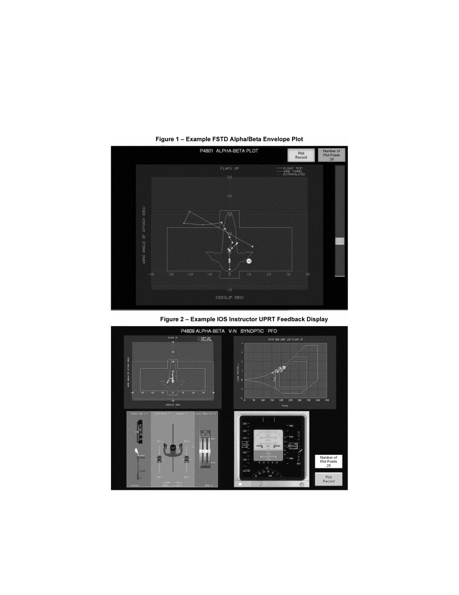
167
Federal Aviation Administration, DOT
Pt. 60, App. A
VerDate Sep<11>2014
14:00 Mar 14, 2024
Jkt 262047
PO 00000
Frm 00177
Fmt 8010
Sfmt 8006
Q:\14\14V2.TXT
PC31
ER30MR16.116</GPH>
aworley on LAPBH6H6L3 with DISTILLER

168
14 CFR Ch. I (1–1–24 Edition)
Pt. 60, App. A
E
ND
I
NFORMATION
B
EGIN
QPS R
EQUIREMENTS
C. Engine and Airframe Icing Evaluation (Table
A1A, Section 2.j.)
1. Applicability: This section applies to all
FSTDs that are used to satisfy training re-
quirements for engine and airframe icing.
New general requirements and objective re-
quirements for simulator qualification have
been developed to define aircraft specific
icing models that support training objectives
for the recognition and recovery from an in-
flight ice accretion event.
2. General Requirements: The qualification
of engine and airframe icing consists of the
following elements that must be considered
when developing ice accretion models for use
in training:
a. Ice accretion models must be developed
to account for training the specific skills re-
quired for recognition of ice accumulation
and execution of the required response.
b. Ice accretion models must be developed
in a manner to contain aircraft specific rec-
ognition cues as determined with aircraft
OEM supplied data or other suitable analyt-
ical methods.
c. At least one qualified ice accretion
model must be objectively tested to dem-
onstrate that the model has been imple-
mented correctly and generates the correct
cues as necessary for training.
3. Statement of Compliance: The SOC as
described in Table A1A, Section 2.j. must
contain the following information to support
FSTD qualification of aircraft specific ice
accretion models:
a. A description of expected aircraft spe-
cific recognition cues and degradation ef-
fects due to a typical in-flight icing encoun-
ter. Typical cues may include loss of lift, de-
crease in stall angle of attack, changes in
pitching moment, decrease in control effec-
tiveness, and changes in control forces in ad-
dition to any overall increase in drag. This
description must be based upon relevant
source data, such as aircraft OEM supplied
data, accident/incident data, or other accept-
able data sources. Where a particular air-
frame has demonstrated vulnerabilities to a
specific type of ice accretion (due to acci-
dent/incident history) which requires specific
training (such as supercooled large-droplet
icing or tailplane icing), ice accretion mod-
els must be developed that address the train-
ing requirements.
b. A description of the data sources uti-
lized to develop the qualified ice accretion
models. Acceptable data sources may be, but
are not limited to, flight test data, aircraft
certification data, aircraft OEM engineering
simulation data, or other analytical methods
based upon established engineering prin-
ciples.
4. Objective Demonstration Testing: The
purpose of the objective demonstration test
is to demonstrate that the ice accretion
models as described in the Statement of
Compliance have been implemented cor-
rectly and demonstrate the proper cues and
effects as defined in the approved data
sources. At least one ice accretion model
must be selected for testing and included in
the Master Qualification Test Guide (MQTG).
Two tests are required to demonstrate en-
gine and airframe icing effects. One test will
demonstrate the FSTDs baseline perform-
ance without icing, and the second test will
demonstrate the aerodynamic effects of ice
accretion relative to the baseline test.
a.
Recorded Parameters: In each of the two
required MQTG cases, a time history record-
ing must be made of the following param-
eters:
i. Altitude;
ii. Airspeed;
iii. Normal Acceleration;
iv. Engine Power/settings;
v. Angle of Attack/Pitch attitude;
vi. Bank Angle;
vii. Flight control inputs;
viii. Stall warning and stall buffet onset; and
ix. Other parameters as necessary to dem-
onstrate the effects of ice accretions.
b.
Demonstration maneuver: The FSTD spon-
sor must select an ice accretion model as
identified in the SOC for testing. The se-
lected maneuver must demonstrate the ef-
fects of ice accretion at high angles of attack
from a trimmed condition through approach
to stall and ‘‘full’’ stall as compared to a
baseline (no ice buildup) test. The ice accre-
tion models must demonstrate the cues nec-
essary to recognize the onset of ice accretion
on the airframe, lifting surfaces, and engines
and provide representative degradation in
performance and handling qualities to the
extent that a recovery can be executed. Typ-
ical recognition cues that may be present de-
pending upon the simulated aircraft include:
i. Decrease in stall angle of attack;
ii. Increase in stall speed;
iii. Increase in stall buffet threshold of per-
ception speed;
iv. Changes in pitching moment;
v. Changes in stall buffet characteristics;
vi. Changes in control effectiveness or con-
trol forces; and
vii. Engine effects (power variation, vibra-
tion, etc.);
The demonstration test may be conducted by
initializing and maintaining a fixed amount
of ice accretion throughout the maneuver in
order to consistently evaluate the aero-
dynamic effects.
VerDate Sep<11>2014
14:00 Mar 14, 2024
Jkt 262047
PO 00000
Frm 00178
Fmt 8010
Sfmt 8002
Q:\14\14V2.TXT
PC31
aworley on LAPBH6H6L3 with DISTILLER

169
Federal Aviation Administration, DOT
Pt. 60, App. B
E
ND
QPS R
EQUIREMENTS
[Doc. No. FAA–2002–12461, 73 FR 26490, May 9,
2008, as amended by Docket FAA–2014–0391,
Amdt. 60–4, 81 FR 18218, 18219, 18240, 18283,
18300, and 18303, Mar. 30, 2016; 81 FR 32016 and
32066, May 20, 2016; Docket FAA–2018–0119,
Amdt. 60–5, 83 FR 9170, Mar. 5, 2018; Amdt. 60–
6, 83 FR 30275, June 27, 2018; Docket No. FAA–
2022–1355, Amdt. No. 60–7, 87 FR 75711, Dec. 9,
2022]
A
PPENDIX
B
TO
P
ART
60—Q
UALIFICATION
P
ERFORMANCE
S
TANDARDS FOR
A
IR
-
PLANE
F
LIGHT
T
RAINING
D
EVICES
llllllllllllllllllllllll
B
EGIN
I
NFORMATION
This appendix establishes the standards for
Airplane FTD evaluation and qualification
at Level 4, Level 5, Level 6, or Level 7. The
Flight Standards Service, is responsible for
the development, application, and implemen-
tation of the standards contained within this
appendix. The procedures and criteria speci-
fied in this appendix will be used by the re-
sponsible Flight Standards office when con-
ducting airplane FTD evaluations.
T
ABLE OF
C
ONTENTS
1. Introduction
2. Applicability (§§ 60.1 and 60.2).
3. Definitions (§ 60.3).
4. Qualification Performance Standards
(§ 60.4).
5. Quality Management System (§ 60.5).
6. Sponsor Qualification Requirements
(§ 60.7).
7. Additional Responsibilities of the Sponsor
(§ 60.9).
8. FTD Use (§ 60.11).
9. FTD Objective Data Requirements (§ 60.13).
10. Special Equipment and Personnel Re-
quirements for Qualification of the FTD
(§ 60.14).
11. Initial (and Upgrade) Qualification Re-
quirements (§ 60.15).
12. Additional Qualifications for Currently
Qualified FTDs (§ 60.16).
13. Previously Qualified FTDs (§ 60.17).
14. Inspection, Continuing Qualification
Evaluation, and Maintenance Require-
ments (§ 60.19).
15. Logging FTD Discrepancies (§ 60.20).
16. Interim Qualification of FTDs for New
Airplane Types or Models (§ 60.21).
17. Modifications to FTDs (§ 60.23).
18. Operations with Missing, Malfunctioning,
or Inoperative Components (§ 60.25).
19. Automatic Loss of Qualification and Pro-
cedures for Restoration of Qualification
(§ 60.27).
20. Other Losses of Qualification and Proce-
dures for Restoration of Qualification
(§ 60.29).
21. Record Keeping and Reporting (§ 60.31).
22. Applications, Logbooks, Reports, and
Records: Fraud, Falsification, or Incor-
rect Statements (§ 60.33).
23. [Reserved]
24. Levels of FTD.
25. FTD Qualification on the Basis of a Bilat-
eral Aviation Safety Agreement (BASA)
(§ 60.37).
Attachment 1 to Appendix B to Part 60—Gen-
eral FTD Requirements.
Attachment 2 to Appendix B to Part 60—
Flight Training Device (FTD) Objective
Tests.
Attachment 3 to Appendix B to Part 60—
Flight Training Device (FTD) Subjective
Evaluation.
Attachment 4 to Appendix B to Part 60—
Sample Documents.
E
ND
I
NFORMATION
llllllllllllllllllllllll
1. I
NTRODUCTION
llllllllllllllllllllllll
B
EGIN
I
NFORMATION
a. This appendix contains background in-
formation as well as regulatory and inform-
ative material as described later in this sec-
tion. To assist the reader in determining
what areas are required and what areas are
permissive, the text in this appendix is di-
vided into two sections: ‘‘QPS Require-
ments’’ and ‘‘Information.’’ The QPS Re-
quirements sections contain details regard-
ing compliance with the part 60 rule lan-
guage. These details are regulatory, but are
found only in this appendix. The Information
sections contain material that is advisory in
nature, and designed to give the user general
information about the regulation.
b. [Reserved]
c. The responsible Flight Standards office
encourages the use of electronic media for
all communication, including any record, re-
port, request, test, or statement required by
this appendix. The electronic media used
must have adequate security provisions and
be acceptable to the responsible Flight
Standards office.
d. Related Reading References.
(1) 14 CFR part 60.
(2) 14 CFR part 61.
(3) 14 CFR part 63.
(4) 14 CFR part 119.
(5) 14 CFR part 121.
(6) 14 CFR part 125.
(7) 14 CFR part 135.
(8) 14 CFR part 141.
(9) 14 CFR part 142.
VerDate Sep<11>2014
14:00 Mar 14, 2024
Jkt 262047
PO 00000
Frm 00179
Fmt 8010
Sfmt 8002
Q:\14\14V2.TXT
PC31
aworley on LAPBH6H6L3 with DISTILLER

170
14 CFR Ch. I (1–1–24 Edition)
Pt. 60, App. B
(10) AC 120–28, as amended, Criteria for Ap-
proval of Category III Landing Weather
Minima.
(11) AC 120–29, as amended, Criteria for Ap-
proving Category I and Category II Landing
Minima for part 121 operators.
(12) AC 120–35, as amended, Flightcrew
Member Line Operational Simulations: Line-
Oriented Flight Training, Special Purpose
Operational Training, Line Operational
Evaluation.
(13) AC 120–41, as amended, Criteria for
Operational Approval of Airborne Wind
Shear Alerting and Flight Guidance Sys-
tems.
(14) AC 120–45, as amended, Airplane Flight
Training Device Qualification.
(14) AC 120–57, as amended, Surface Move-
ment Guidance and Control System
(SMGCS).
(15) AC 150/5300–13, as amended, Airport De-
sign.
(16) AC 150/5340–1, as amended, Standards
for Airport Markings.
(17) AC 150/5340–4, as amended, Installation
Details for Runway Centerline Touchdown
Zone Lighting Systems.
(18) AC 150/5340–19, as amended, Taxiway
Centerline Lighting System.
(19) AC 150/5340–24, as amended, Runway
and Taxiway Edge Lighting System.
(20) AC 150/5345–28, as amended, Precision
Approach Path Indicator (PAPI) Systems.
(21) International Air Transport Associa-
tion document, ‘‘Flight Simulation Training
Device Design and Performance Data Re-
quirements,’’ as amended.
(22) AC 25–7, as amended, Flight Test Guide
for Certification of Transport Category Air-
planes.
(23) AC 23–8A, as amended, Flight Test
Guide for Certification of Part 23 Airplanes.
(24) International Civil Aviation Organiza-
tion (ICAO) Manual of Criteria for the Quali-
fication of Flight Simulation Training De-
vices, as amended.
(25) Aeroplane Flight Simulation Training
Device Evaluation Handbook, Volume I, as
amended and Volume II, as amended, The
Royal Aeronautical Society, London, UK.
(26) FAA Airman Certification Standards
and Practical Test Standards for Airline
Transport Pilot, Type Ratings, Commercial
Pilot, and Instrument Ratings.
(27) The FAA Aeronautical Information
Manual (AIM). An electronic version of the
AIM is on the Internet at
http://www.faa.gov/
atpubs.
(28) Aeronautical Radio, Inc. (ARINC) doc-
ument number 436, titled
Guidelines For Elec-
tronic Qualification Test Guide (as amended).
(29) Aeronautical Radio, Inc. (ARINC) doc-
ument 610, Guidance for
Design and Integra-
tion of Aircraft Avionics Equipment in Simula-
tors (as amended).
llllllllllllllllllllllll
E
ND
I
NFORMATION
2. A
PPLICABILITY
(§§ 60.1
AND
60.2)
llllllllllllllllllllllll
B
EGIN
I
NFORMATION
No additional regulatory or informational
material applies to § 60.1, Applicability, or to
§ 60.2, Applicability of sponsor rules to person
who are not sponsors and who are engaged in
certain unauthorized activities.
3. D
EFINITIONS
(§ 60.3)
See appendix F of this part for a list of
definitions and abbreviations from part 1,
part 60, and the QPS appendices of part 60.
4. Q
UALIFICATION
P
ERFORMANCE
S
TANDARDS
(§ 60.4)
No additional regulatory or informational
material applies to § 60.4, Qualification Per-
formance Standards.
5. Q
UALITY
M
ANAGEMENT
S
YSTEM
(§ 60.5)
Additional regulatory material and infor-
mational material regarding Quality Man-
agement Systems for FTDs may be found in
appendix E of this part.
E
ND
I
NFORMATION
llllllllllllllllllllllll
6. S
PONSOR
Q
UALIFICATION
R
EQUIREMENTS
.
(§ 60.7).
llllllllllllllllllllllll
B
EGIN
I
NFORMATION
a. The intent of the language in § 60.7(b) is
to have a specific FTD, identified by the
sponsor, used at least once in an FAA-ap-
proved flight training program for the air-
plane simulated during the 12-month period
described. The identification of the specific
FTD may change from one 12-month period
to the next 12-month period as long as that
sponsor sponsors and uses at least one FTD
at least once during the prescribed period.
There is no minimum number of hours or
minimum FTD periods required.
b. The following examples describe accept-
able operational practices:
(1) Example One.
(a) A sponsor is sponsoring a single, spe-
cific FTD for its own use, in its own facility
or elsewhere— this single FTD forms the
basis for the sponsorship. The sponsor uses
that FTD at least once in each 12-month pe-
riod in that sponsor’s FAA-approved flight
training program for the airplane simulated.
This 12-month period is established accord-
ing to the following schedule:
(i) If the FTD was qualified prior to May
30, 2008, the 12-month period begins on the
date of the first continuing qualification
evaluation conducted in accordance with
VerDate Sep<11>2014
14:00 Mar 14, 2024
Jkt 262047
PO 00000
Frm 00180
Fmt 8010
Sfmt 8002
Q:\14\14V2.TXT
PC31
aworley on LAPBH6H6L3 with DISTILLER

171
Federal Aviation Administration, DOT
Pt. 60, App. B
§ 60.19 after May 30, 2008, and continues for
each subsequent 12-month period;
(ii) A device qualified on or after May 30,
2008, will be required to undergo an initial or
upgrade evaluation in accordance with
§ 60.15. Once the initial or upgrade evaluation
is complete, the first continuing qualifica-
tion evaluation will be conducted within 6
months. The 12 month continuing qualifica-
tion evaluation cycle begins on that date and
continues for each subsequent 12-month pe-
riod.
(b) There is no minimum number of hours
of FTD use required.
(c) The identification of the specific FTD
may change from one 12-month period to the
next 12-month period as long as that sponsor
sponsors and uses at least one FTD at least
once during the prescribed period.
(2) Example Two.
(a) A sponsor sponsors an additional num-
ber of FTDs, in its facility or elsewhere.
Each additionally sponsored FTD must be—
(i) Used by the sponsor in the sponsor’s
FAA-approved flight training program for
the airplane simulated (as described in
§ 60.7(d)(1)); or
(ii) Used by another FAA certificate holder
in that other certificate holder’s FAA-ap-
proved flight training program for the air-
plane simulated (as described in § 60.7(d)(1)).
This 12-month period is established in the
same manner as in example one; or
(iii) Provided a statement each year from a
qualified pilot, (after having flown the air-
plane, not the subject FTD or another FTD,
during the preceding 12-month period) stat-
ing that the subject FTD’s performance and
handling qualities represent the airplane (as
described in § 60.7(d)(2)). This statement is
provided at least once in each 12-month pe-
riod established in the same manner as in ex-
ample one.
(b) There is no minimum number of hours
of FTD use required.
(3) Example Three.
(a) A sponsor in New York (in this exam-
ple, a Part 142 certificate holder) establishes
‘‘satellite’’ training centers in Chicago and
Moscow.
(b) The satellite function means that the
Chicago and Moscow centers must operate
under the New York center’s certificate (in
accordance with all of the New York center’s
practices, procedures, and policies; e.g., in-
structor and/or technician training/checking
requirements, record keeping, QMS pro-
gram).
(c) All of the FTDs in the Chicago and Mos-
cow centers could be dry-leased (i.e., the cer-
tificate holder does not have and use FAA-
approved flight training programs for the
FTDs in the Chicago and Moscow centers)
because—
(i) Each FTD in the Chicago center and
each FTD in the Moscow center is used at
least once each 12-month period by another
FAA certificate holder in that other certifi-
cate holder’s FAA-approved flight training
program for the airplane (as described in
§ 60.7(d)(1)); or
(ii) A statement is obtained from a quali-
fied pilot (having flown the airplane, not the
subject FTD or another FTD during the pre-
ceding 12-month period) stating that the per-
formance and handling qualities of each FTD
in the Chicago and Moscow centers rep-
resents the airplane (as described in
§ 60.7(d)(2)).
E
ND
I
NFORMATION
llllllllllllllllllllllll
7. A
DDITIONAL
R
ESPONSIBILITIES OF THE
S
PONSOR
(§ 60.9)
llllllllllllllllllllllll
B
EGIN
I
NFORMATION
The phrase ‘‘as soon as practicable’’ in
§ 60.9(a) means without unnecessarily dis-
rupting or delaying beyond a reasonable
time the training, evaluation, or experience
being conducted in the FTD.
8. FTD U
SE
(§ 60.11)
No additional regulatory or informational
material applies to § 60.11, FTD use.
E
ND
I
NFORMATION
llllllllllllllllllllllll
9. FTD Objective Data Requirements
(§ 60.13)
llllllllllllllllllllllll
B
EGIN
QPS R
EQUIREMENTS
a. Flight test data used to validate FTD
performance and handling qualities must
have been gathered in accordance with a
flight test program containing the following:
(1) A flight test plan consisting of:
(a) The maneuvers and procedures required
for aircraft certification and simulation pro-
gramming and validation.
(b) For each maneuver or procedure—
(i) The procedures and control input the
flight test pilot and/or engineer used.
(ii) The atmospheric and environmental
conditions.
(iii) The initial flight conditions.
(iv) The airplane configuration, including
weight and center of gravity.
(v) The data to be gathered.
(vi) All other information necessary to
recreate the flight test conditions in the
FTD.
(2) Appropriately qualified flight test per-
sonnel.
(3) An understanding of the accuracy of the
data to be gathered using appropriate alter-
native data sources, procedures, and instru-
mentation that is traceable to a recognized
VerDate Sep<11>2014
14:00 Mar 14, 2024
Jkt 262047
PO 00000
Frm 00181
Fmt 8010
Sfmt 8002
Q:\14\14V2.TXT
PC31
aworley on LAPBH6H6L3 with DISTILLER

172
14 CFR Ch. I (1–1–24 Edition)
Pt. 60, App. B
standard as described in Attachment 2, Table
B2F of this appendix.
(4) Appropriate and sufficient data acquisi-
tion equipment or system(s), including ap-
propriate data reduction and analysis meth-
ods and techniques, acceptable to the FAA’s
Aircraft Certification Service.
b. The data, regardless of source, must be
presented:
(1) In a format that supports the FTD vali-
dation process;
(2) In a manner that is clearly readable and
annotated correctly and completely;
(3) With resolution sufficient to determine
compliance with the tolerances set forth in
Attachment 2, Table B2A, Appendix B;
(4) With any necessary guidance informa-
tion provided; and
(5) Without alteration, adjustments, or
bias. Data may be corrected to address
known data calibration errors provided that
an explanation of the methods used to cor-
rect the errors appears in the QTG. The cor-
rected data may be re-scaled, digitized, or
otherwise manipulated to fit the desired
presentation.
c. After completion of any additional flight
test, a flight test report must be submitted
in support of the validation data. The report
must contain sufficient data and rationale to
support qualification of the FTD at the level
requested.
d. As required by § 60.13(f), the sponsor
must notify the responsible Flight Standards
office when it becomes aware that an addi-
tion to or a revision of the flight related
data or airplane systems related data is
available if this data is used to program and
operate a qualified FTD. The data referred to
in this sub-section are those data that are
used to validate the performance, handling
qualities, or other characteristics of the air-
craft, including data related to any relevant
changes occurring after the type certifi-
cation is issued. The sponsor must—
(1) Within 10 calendar days, notify the re-
sponsible Flight Standards office of the ex-
istence of this data; and
(2) Within 45 calendar days, notify the re-
sponsible Flight Standards office of—
(i) The schedule to incorporate this data
into the FTD; or
(ii) The reason for not incorporating this
data into the FTD.
e. In those cases where the objective test
results authorize a ‘‘snapshot test’’ or a ‘‘se-
ries of snapshot test results’’ in lieu of a
time-history result, the sponsor or other
data provider must ensure that a steady
state condition exists at the instant of time
captured by the ‘‘snapshot.’’ The steady
state condition must exist from 4 seconds
prior to, through 1 second following, the in-
stant of time captured by the snap shot.
E
ND
QPS R
EQUIREMENTS
llllllllllllllllllllllll
B
EGIN
I
NFORMATION
f. The FTD sponsor is encouraged to main-
tain a liaison with the manufacturer of the
aircraft being simulated (or with the holder
of the aircraft type certificate for the air-
craft being simulated if the manufacturer is
no longer in business), and if appropriate,
with the person having supplied the aircraft
data package for the FTD in order to facili-
tate the notification described in this para-
graph.
g. It is the intent of the responsible Flight
Standards office that for new aircraft enter-
ing service, at a point well in advance of
preparation of the QTG, the sponsor should
submit to the responsible Flight Standards
office for approval, a descriptive document
(see Appendix A, Table A2C, Sample Valida-
tion Data Roadmap for Airplanes) containing
the plan for acquiring the validation data,
including data sources. This document
should clearly identify sources of data for all
required tests, a description of the validity
of these data for a specific engine type and
thrust rating configuration, and the revision
levels of all avionics affecting the perform-
ance or flying qualities of the aircraft. Addi-
tionally, this document should provide other
information such as the rationale or expla-
nation for cases where data or data param-
eters are missing, instances where engineer-
ing simulation data are used, or where flight
test methods require further explanations. It
should also provide a brief narrative describ-
ing the cause and effect of any deviation
from data requirements. The aircraft manu-
facturer may provide this document.
h. There is no requirement for any flight
test data supplier to submit a flight test
plan or program prior to gathering flight
test data. However, the responsible Flight
Standards office notes that inexperienced
data gatherers often provide data that is ir-
relevant, improperly marked, or lacking ade-
quate justification for selection. Other prob-
lems include inadequate information regard-
ing initial conditions or test maneuvers. The
responsible Flight Standards office has been
forced to refuse these data submissions as
validation data for an FTD evaluation. It is
for this reason that the responsible Flight
Standards office recommends that any data
supplier not previously experienced in this
area review the data necessary for program-
ming and for validating the performance of
the FTD and discuss the flight test plan an-
ticipated for acquiring such data with the re-
sponsible Flight Standards office well in ad-
vance of commencing the flight tests.
i. The responsible Flight Standards office
will consider, on a case-by-case basis, wheth-
er to approve supplemental validation data
derived from flight data recording systems
such as a Quick Access Recorder or Flight
Data Recorder.
VerDate Sep<11>2014
14:00 Mar 14, 2024
Jkt 262047
PO 00000
Frm 00182
Fmt 8010
Sfmt 8002
Q:\14\14V2.TXT
PC31
aworley on LAPBH6H6L3 with DISTILLER

173
Federal Aviation Administration, DOT
Pt. 60, App. B
E
ND
I
NFORMATION
llllllllllllllllllllllll
10. S
PECIAL
E
QUIPMENT AND
P
ERSONNEL
R
E
-
QUIREMENTS FOR
Q
UALIFICATION OF THE
FTD
(§ 60.14).
llllllllllllllllllllllll
B
EGIN
I
NFORMATION
a. In the event that the responsible Flight
Standards office determines that special
equipment or specifically qualified persons
will be required to conduct an evaluation,
the responsible Flight Standards office will
make every attempt to notify the sponsor at
least one (1) week, but in no case less than 72
hours, in advance of the evaluation. Exam-
ples of special equipment include flight con-
trol measurement devices, accelerometers,
or oscilloscopes. Examples of specially quali-
fied personnel include individuals specifi-
cally qualified to install or use any special
equipment when its use is required.
b. Examples of a special evaluation include
an evaluation conducted after: An FTD is
moved; at the request of the TPAA; or as a
result of comments received from users of
the FTD that raise questions about the con-
tinued qualification or use of the FTD.
E
ND
I
NFORMATION
llllllllllllllllllllllll
11. I
NITIAL
(
AND
U
PGRADE
) Q
UALIFICATION
R
EQUIREMENTS
(§ 60.15).
llllllllllllllllllllllll
B
EGIN
QPS R
EQUIREMENT
a. In order to be qualified at a particular
qualification level, the FTD must:
(1) Meet the general requirements listed in
Attachment 1 of this appendix;
(2) Meet the objective testing requirements
listed in Attachment 2 of this appendix
(Level 4 FTDs do not require objective tests);
and
(3) Satisfactorily accomplish the subjec-
tive tests listed in Attachment 3 of this ap-
pendix.
b. The request described in § 60.15(a) must
include all of the following:
(1) A statement that the FTD meets all of
the applicable provisions of this part and all
applicable provisions of the QPS.
(2) Unless otherwise authorized through
prior coordination with the responsible
Flight Standards office, a confirmation that
the sponsor will forward to the responsible
Flight Standards office the statement de-
scribed in § 60.15(b) in such time as to be re-
ceived no later than 5 business days prior to
the scheduled evaluation and may be for-
warded to the responsible Flight Standards
office via traditional or electronic means.
(3) Except for a Level 4 FTD, a QTG, ac-
ceptable to the responsible Flight Standards
office, that includes all of the following:
(a) Objective data obtained from aircraft
testing or another approved source.
(b) Correlating objective test results ob-
tained from the performance of the FTD as
prescribed in the appropriate QPS.
(c) The result of FTD subjective tests pre-
scribed in the appropriate QPS.
(d) A description of the equipment nec-
essary to perform the evaluation for initial
qualification and the continuing qualifica-
tion evaluations.
c. The QTG described in paragraph a(3) of
this section, must provide the documented
proof of compliance with the FTD objective
tests in Attachment 2, Table B2A of this ap-
pendix.
d. The QTG is prepared and submitted by
the sponsor, or the sponsor?s agent on behalf
of the sponsor, to the responsible Flight
Standards office for review and approval, and
must include, for each objective test:
(1) Parameters, tolerances, and flight con-
ditions;
(2) Pertinent and complete instructions for
conducting automatic and manual tests;
(3) A means of comparing the FTD test re-
sults to the objective data;
(4) Any other information as necessary to
assist in the evaluation of the test results;
(5) Other information appropriate to the
qualification level of the FTD.
e. The QTG described in paragraphs (a)(3)
and (b) of this section, must include the fol-
lowing:
(1) A QTG cover page with sponsor and
FAA approval signature blocks (see Attach-
ment 4, Figure B4C, of this appendix, for a
sample QTG cover page).
(2) [Reserved]
(3) An FTD information page that provides
the information listed in this paragraph, if
applicable (see Attachment 4, Figure B4B, of
this appendix, for a sample FTD information
page). For convertible FTDs, the sponsor
must submit a separate page for each con-
figuration of the FTD.
(a) The sponsor’s FTD identification num-
ber or code.
(b) The airplane model and series being
simulated.
(c) The aerodynamic data revision number
or reference.
(d) The source of the basic aerodynamic
model and the aerodynamic coefficient data
used to modify the basic model.
(e) The engine model(s) and its data revi-
sion number or reference.
(f) The flight control data revision number
or reference.
(g) The flight management system identi-
fication and revision level.
(h) The FTD model and manufacturer.
(i) The date of FTD manufacture.
(j) The FTD computer identification.
VerDate Sep<11>2014
14:00 Mar 14, 2024
Jkt 262047
PO 00000
Frm 00183
Fmt 8010
Sfmt 8002
Q:\14\14V2.TXT
PC31
aworley on LAPBH6H6L3 with DISTILLER

174
14 CFR Ch. I (1–1–24 Edition)
Pt. 60, App. B
(k) The visual system model and manufac-
turer, including display type.
(l) The motion system type and manufac-
turer, including degrees of freedom.
(4) A Table of Contents.
(5) A log of revisions and a list of effective
pages.
(6) List of all relevant data references.
(7) A glossary of terms and symbols used
(including sign conventions and units).
(8) Statements of compliance and capa-
bility (SOCs) with certain requirements.
(9) Recording procedures or equipment re-
quired to accomplish the objective tests.
(10) The following information for each ob-
jective test designated in Attachment 2 of
this appendix, as applicable to the qualifica-
tion level sought:
(a) Name of the test.
(b) Objective of the test.
(c) Initial conditions.
(d) Manual test procedures.
(e) Automatic test procedures (if applica-
ble).
(f) Method for evaluating FTD objective
test results.
(g) List of all relevant parameters driven
or constrained during the automatic test(s).
(h) List of all relevant parameters driven
or constrained during the manual test(s).
(i) Tolerances for relevant parameters.
(j) Source of Validation Data (document
and page number).
(k) Copy of the Validation Data (if located
in a separate binder, a cross reference for the
identification and page number for pertinent
data location must be provided).
(l) FTD Objective Test Results as obtained
by the sponsor. Each test result must reflect
the date completed and must be clearly la-
beled as a product of the device being tested.
f. A convertible FTD is addressed as a sepa-
rate FTD for each model and series airplane
to which it will be converted and for the
FAA qualification level sought. The respon-
sible Flight Standards office will conduct an
evaluation for each configuration. If a spon-
sor seeks qualification for two or more mod-
els of an airplane type using a convertible
FTD, the sponsor must provide a QTG for
each airplane model, or a QTG for the first
airplane model and a supplement to that
QTG for each additional airplane model. The
responsible Flight Standards office will con-
duct evaluations for each airplane model.
g. The form and manner of presentation of
objective test results in the QTG must in-
clude the following:
(1) The sponsor’s FTD test results must be
recorded in a manner acceptable to the re-
sponsible Flight Standards office, that al-
lows easy comparison of the FTD test results
to the validation data (e.g., use of a multi-
channel recorder, line printer, cross plotting,
overlays, transparencies).
(2) FTD results must be labeled using ter-
minology common to airplane parameters as
opposed to computer software identifica-
tions.
(3) Validation data documents included in
a QTG may be photographically reduced only
if such reduction will not alter the graphic
scaling or cause difficulties in scale interpre-
tation or resolution.
(4) Scaling on graphical presentations
must provide the resolution necessary to
evaluate the parameters shown in Attach-
ment 2, Table B2A of this appendix.
(5) Tests involving time histories, data
sheets (or transparencies thereof) and FTD
test results must be clearly marked with ap-
propriate reference points to ensure an accu-
rate comparison between FTD and airplane
with respect to time. Time histories recorded
via a line printer are to be clearly identified
for cross-plotting on the airplane data. Over-
plots may not obscure the reference data.
h. The sponsor may elect to complete the
QTG objective and subjective tests at the
manufacturer’s facility or at the sponsor’s
training facility (or other sponsor designated
location where training will take place). If
the tests are conducted at the manufactur-
er’s facility, the sponsor must repeat at least
one-third of the tests at the sponsor’s train-
ing facility in order to substantiate FTD per-
formance. The QTG must be clearly anno-
tated to indicate when and where each test
was accomplished. Tests conducted at the
manufacturer’s facility and at the sponsor’s
designated training facility must be con-
ducted after the FTD is assembled with sys-
tems and sub-systems functional and oper-
ating in an interactive manner. The test re-
sults must be submitted to the responsible
Flight Standards office.
i. The sponsor must maintain a copy of the
MQTG at the FTD location.
j. All FTDs for which the initial qualifica-
tion is conducted after May 30, 2014, must
have an electronic MQTG (Emqtg) including
all objective data obtained from airplane
testing, or another approved source (refor-
matted or digitized), together with corre-
lating objective test results obtained from
the performance of the FTD (reformatted or
digitized) as prescribed in this appendix. The
Emqtg must also contain the general FTD
performance or demonstration results (refor-
matted or digitized) prescribed in this appen-
dix, and a description of the equipment nec-
essary to perform the initial qualification
evaluation and the continuing qualification
evaluations. The Emqtg must include the
original validation data used to validate
FTD performance and handling qualities in
either the original digitized format from the
data supplier or an electronic scan of the
original time-history plots that were pro-
vided by the data supplier. A copy of the
Emqtg must be provided to the responsible
Flight Standards office.
k. All other FTDs (not covered in subpara-
graph ‘‘j’’) must have an electronic copy of
VerDate Sep<11>2014
14:00 Mar 14, 2024
Jkt 262047
PO 00000
Frm 00184
Fmt 8010
Sfmt 8002
Q:\14\14V2.TXT
PC31
aworley on LAPBH6H6L3 with DISTILLER

175
Federal Aviation Administration, DOT
Pt. 60, App. B
the MQTG by and after May 30, 2014. An elec-
tronic copy of the copy of the MQTG must be
provided to the responsible Flight Standards
office. This may be provided by an electronic
scan presented in a Portable Document File
(PDF), or similar format acceptable to the
responsible Flight Standards office.
l. During the initial (or upgrade) qualifica-
tion evaluation conducted by the responsible
Flight Standards office, the sponsor must
also provide a person knowledgeable about
the operation of the aircraft and the oper-
ation of the FTD.
E
ND
QPS R
EQUIREMENTS
llllllllllllllllllllllll
B
EGIN
I
NFORMATION
m. Only those FTDs that are sponsored by
a certificate holder as defined in Appendix F
will be evaluated by the responsible Flight
Standards office. However, other FTD eval-
uations may be conducted on a case-by-case
basis as the Administrator deems appro-
priate, but only in accordance with applica-
ble agreements.
n. The responsible Flight Standards office
will conduct an evaluation for each configu-
ration, and each FTD must be evaluated as
completely as possible. To ensure a thorough
and uniform evaluation, each FTD is sub-
jected to the general FTD requirements in
Attachment 1 of this appendix, the objective
tests listed in Attachment 2 of this appendix,
and the subjective tests listed in Attachment
3 of this appendix. The evaluations described
herein will include, but not necessarily be
limited to the following:
(1) Airplane responses, including longitu-
dinal and lateral-directional control re-
sponses (see Attachment 2 of this appendix);
(2) Performance in authorized portions of
the simulated airplane’s operating envelope,
to include tasks evaluated by the responsible
Flight Standards office in the areas of sur-
face operations, takeoff, climb, cruise, de-
scent, approach and landing, as well as ab-
normal and emergency operations (see At-
tachment 2 of this appendix);
(3) Control checks (see Attachment 1 and
Attachment 2 of this appendix);
(4) Flight deck configuration (see Attach-
ment 1 of this appendix);
(5) Pilot, flight engineer, and instructor
station functions checks (see Attachment 1
and Attachment 3 of this appendix);
(6) Airplane systems and sub-systems (as
appropriate) as compared to the airplane
simulated (see Attachment 1 and Attach-
ment 3 of this appendix);
(7) FTD systems and sub-systems, includ-
ing force cueing (motion), visual, and aural
(sound) systems, as appropriate (see Attach-
ment 1 and Attachment 2 of this appendix);
and
(8) Certain additional requirements, de-
pending upon the qualification level sought,
including equipment or circumstances that
may become hazardous to the occupants. The
sponsor may be subject to Occupational
Safety and Health Administration require-
ments.
o. The responsible Flight Standards office
administers the objective and subjective
tests, which includes an examination of func-
tions. The tests include a qualitative assess-
ment of the FTD by a pilot from the respon-
sible Flight Standards office. The evaluation
team leader may assign other qualified per-
sonnel to assist in accomplishing the func-
tions examination and/or the objective and
subjective tests performed during an evalua-
tion when required.
(1) Objective tests provide a basis for meas-
uring and evaluating FTD performance and
determining compliance with the require-
ments of this part.
(2) Subjective tests provide a basis for:
(a) Evaluating the capability of the FTD to
perform over a typical utilization period;
(b) Determining that the FTD satisfac-
torily simulates each required task;
(c) Verifying correct operation of the FTD
controls, instruments, and systems; and
(d) Demonstrating compliance with the re-
quirements of this part.
p. The tolerances for the test parameters
listed in Attachment 2 of this appendix re-
flect the range of tolerances acceptable to
the responsible Flight Standards office for
FTD validation and are not to be confused
with design tolerances specified for FTD
manufacture. In making decisions regarding
tests and test results, the responsible Flight
Standards office relies on the use of oper-
ational and engineering judgment in the ap-
plication of data (including consideration of
the way in which the flight test was flown
and way the data was gathered and applied),
data presentations, and the applicable toler-
ances for each test.
q. In addition to the scheduled continuing
qualification evaluation, each FTD is subject
to evaluations conducted by the responsible
Flight Standards office at any time without
prior notification to the sponsor. Such eval-
uations would be accomplished in a normal
manner (i.e., requiring exclusive use of the
FTD for the conduct of objective and subjec-
tive tests and an examination of functions) if
the FTD is not being used for flight crew-
member training, testing, or checking. How-
ever, if the FTD were being used, the evalua-
tion would be conducted in a non-exclusive
manner. This non-exclusive evaluation will
be conducted by the FTD evaluator accom-
panying the check airman, instructor, Air-
crew Program Designee (APD), or FAA in-
spector aboard the FTD along with the stu-
dent(s) and observing the operation of the
FTD during the training, testing, or check-
ing activities.
VerDate Sep<11>2014
14:00 Mar 14, 2024
Jkt 262047
PO 00000
Frm 00185
Fmt 8010
Sfmt 8002
Q:\14\14V2.TXT
PC31
aworley on LAPBH6H6L3 with DISTILLER

176
14 CFR Ch. I (1–1–24 Edition)
Pt. 60, App. B
r. Problems with objective test results are
handled as follows:
(1) If a problem with an objective test re-
sult is detected by the evaluation team dur-
ing an evaluation, the test may be repeated
or the QTG may be amended.
(2) If it is determined that the results of an
objective test do not support the qualifica-
tion level requested but do support a lower
level, the responsible Flight Standards office
may qualify the FTD at a lower level. For
example, if a Level 6 evaluation is requested,
but the FTD fails to meet the spiral stability
test tolerances, it could be qualified at Level
5.
s. After an FTD is successfully evaluated,
the responsible Flight Standards office
issues an SOQ to the sponsor, the responsible
Flight Standards office recommends the
FTD to the TPAA, who will approve the FTD
for use in a flight training program. The SOQ
will be issued at the satisfactory conclusion
of the initial or continuing qualification
evaluation and will list the tasks for which
the FTD is qualified, referencing the tasks
described in Table B1B in Attachment 1 of
this appendix. However, it is the sponsor’s
responsibility to obtain TPAA approval prior
to using the FTD in an FAA-approved flight
training program.
t. Under normal circumstances, the respon-
sible Flight Standards office establishes a
date for the initial or upgrade evaluation
within ten (10) working days after deter-
mining that a complete QTG is acceptable.
Unusual circumstances may warrant estab-
lishing an evaluation date before this deter-
mination is made. A sponsor may schedule
an evaluation date as early as 6 months in
advance. However, there may be a delay of 45
days or more in rescheduling and completing
the evaluation if the sponsor is unable to
meet the scheduled date. See Attachment 4,
Figure B4A, Sample Request for Initial, Up-
grade, or Reinstatement Evaluation, of this
appendix.
u. The numbering system used for objec-
tive test results in the QTG should closely
follow the numbering system set out in At-
tachment 2, FTD Objective Tests, Table B2A,
of this appendix.
v. Contact the responsible Flight Stand-
ards office for additional information regard-
ing the preferred qualifications of pilots used
to meet the requirements of § 60.15(d).
w. Examples of the exclusions for which
the FTD might not have been subjectively
tested by the sponsor or the responsible
Flight Standards office and for which quali-
fication might not be sought or granted, as
described in § 60.15(g)(6), include engine out
maneuvers or circling approaches.
12. A
DDITIONAL
Q
UALIFICATIONS FOR
C
URRENTLY
Q
UALIFIED
FTD
S
(§ 60.16).
No additional regulatory or informational
material applies to § 60.16, Additional Quali-
fications for a Currently Qualified FTD.
E
ND
I
NFORMATION
llllllllllllllllllllllll
13. P
REVIOUSLY
Q
UALIFIED
FTD
S
(§ 60.17).
llllllllllllllllllllllll
B
EGIN
QPS R
EQUIREMENTS
a. In instances where a sponsor plans to re-
move an FTD from active status for a period
of less than two years, the following proce-
dures apply:
(1) The responsible Flight Standards office
must be notified in writing and the notifica-
tion must include an estimate of the period
that the FTD will be inactive;
(2) Continuing Qualification evaluations
will not be scheduled during the inactive pe-
riod;
(3) The responsible Flight Standards office
will remove the FTD from the list of quali-
fied FTDs on a mutually established date not
later than the date on which the first missed
continuing qualification evaluation would
have been scheduled;
(4) Before the FTD is restored to qualified
status, it must be evaluated by the respon-
sible Flight Standards office. The evaluation
content and the time required to accomplish
the evaluation is based on the number of
continuing qualification evaluations and
sponsor-conducted quarterly inspections
missed during the period of inactivity.
(5) The sponsor must notify the responsible
Flight Standards office of any changes to the
original scheduled time out of service;
b. FTDs qualified prior to May 31, 2016, and
replacement FTD systems, are not required
to meet the general FTD requirements, the
objective test requirements, and the subjec-
tive test requirements of Attachments 1, 2,
and 3 of this appendix as long as the FTD
continues to meet the test requirements con-
tained in the MQTG developed under the
original qualification basis.
c. [Reserved]
d. FTDs qualified prior to May 31, 2016,
may be updated. If an evaluation is deemed
appropriate or necessary by the responsible
Flight Standards office after such an update,
the evaluation will not require an evaluation
to standards beyond those against which the
FTD was originally qualified.
e. Other certificate holders or persons de-
siring to use an FTD may contract with FTD
sponsors to use FTDs previously qualified at
a particular level for an airplane type and
approved for use within an FAA-approved
flight training program. Such FTDs are not
required to undergo an additional qualifica-
tion process, except as described in § 60.16.
VerDate Sep<11>2014
14:00 Mar 14, 2024
Jkt 262047
PO 00000
Frm 00186
Fmt 8010
Sfmt 8002
Q:\14\14V2.TXT
PC31
aworley on LAPBH6H6L3 with DISTILLER

177
Federal Aviation Administration, DOT
Pt. 60, App. B
f. Each FTD user must obtain approval
from the appropriate TPAA to use any FTD
in an FAA-approved flight training program.
g. The intent of the requirement listed in
§ 60.17(b), for each FTD to have an SOQ with-
in 6 years, is to have the availability of that
statement (including the configuration list
and the limitations to authorizations) to
provide a complete picture of the FTD inven-
tory regulated by the FAA. The issuance of
the statement will not require any addi-
tional evaluation or require any adjustment
to the evaluation basis for the FTD.
h. Downgrading of an FTD is a permanent
change in qualification level and will neces-
sitate the issuance of a revised SOQ to re-
flect the revised qualification level, as ap-
propriate. If a temporary restriction is
placed on an FTD because of a missing, mal-
functioning, or inoperative component or on-
going repairs, the restriction is not a perma-
nent change in qualification level. Instead,
the restriction is temporary and is removed
when the reason for the restriction has been
resolved.
i. The responsible Flight Standards office
will determine the evaluation criteria for an
FTD that has been removed from active sta-
tus for a prolonged period. The criteria will
be based on the number of continuing quali-
fication evaluations and quarterly inspec-
tions missed during the period of inactivity.
For example, if the FTD were out of service
for a 1 year period, it would be necessary to
complete the entire QTG, since all of the
quarterly evaluations would have been
missed. The responsible Flight Standards of-
fice will also consider how the FTD was
stored, whether parts were removed from the
FTD and whether the FTD was disassembled.
j. The FTD will normally be requalified
using the FAA-approved MQTG and the cri-
teria that was in effect prior to its removal
from qualification. However, inactive periods
of 2 years or more will require re-qualifica-
tion under the standards in effect and cur-
rent at the time of requalification.
E
ND
I
NFORMATION
llllllllllllllllllllllll
14. I
NSPECTION
, C
ONTINUING
Q
UALIFICATION
,
E
VALUATION
,
AND
M
AINTENANCE
R
EQUIRE
-
MENTS
(§ 60.19).
llllllllllllllllllllllll
B
EGIN
QPS R
EQUIREMENT
a. The sponsor must conduct a minimum of
four evenly spaced inspections throughout
the year. The objective test sequence and
content of each inspection in this sequence
must be developed by the sponsor and must
be acceptable to the responsible Flight
Standards office.
b. The description of the functional pre-
flight check must be contained in the spon-
sor’s QMS.
c. Record ‘‘functional preflight’’ in the
FTD discrepancy log book or other accept-
able location, including any item found to be
missing, malfunctioning, or inoperative.
d. During the continuing qualification
evaluation conducted by the responsible
Flight Standards office, the sponsor must
also provide a person knowledgeable about
the operation of the aircraft and the oper-
ation of the FTD.
E
ND
QPS R
EQUIREMENTS
llllllllllllllllllllllll
B
EGIN
I
NFORMATION
e. The sponsor’s test sequence and the con-
tent of each quarterly inspection required in
§ 60.19(a)(1) should include a balance and a
mix from the objective test requirement
areas listed as follows:
(1) Performance.
(2) Handling qualities.
(3) Motion system (where appropriate).
(4) Visual system (where appropriate).
(5) Sound system (where appropriate).
(6) Other FTD systems.
f. If the evaluator plans to accomplish spe-
cific tests during a normal continuing quali-
fication evaluation that requires the use of
special equipment or technicians, the spon-
sor will be notified as far in advance of the
evaluation as practical; but not less than 72
hours. Examples of such tests include
latencies, control sweeps, or motion or vis-
ual system tests.
g. The continuing qualification evalua-
tions described in § 60.19(b) will normally re-
quire 4 hours of FTD time. However, flexi-
bility is necessary to address abnormal situ-
ations or situations involving aircraft with
additional levels of complexity (e.g., com-
puter controlled aircraft). The sponsor
should anticipate that some tests may re-
quire additional time. The continuing quali-
fication evaluations will consist of the fol-
lowing:
(1) Review of the results of the quarterly
inspections conducted by the sponsor since
the last scheduled continuing qualification
evaluation.
(2) A selection of approximately 8 to 15 ob-
jective tests from the MQTG that provide an
adequate opportunity to evaluate the per-
formance of the FTD. The tests chosen will
be performed either automatically or manu-
ally and should be able to be conducted with-
in approximately one-third (1/3) of the allot-
ted FTD time.
(3) A subjective evaluation of the FTD to
perform a representative sampling of the
tasks set out in attachment 3 of this appen-
dix. This portion of the evaluation should
VerDate Sep<11>2014
14:00 Mar 14, 2024
Jkt 262047
PO 00000
Frm 00187
Fmt 8010
Sfmt 8002
Q:\14\14V2.TXT
PC31
aworley on LAPBH6H6L3 with DISTILLER

178
14 CFR Ch. I (1–1–24 Edition)
Pt. 60, App. B
take approximately two-thirds (2/3) of the al-
lotted FTD time.
(4) An examination of the functions of the
FTD may include the motion system, visual
system, sound system as applicable, instruc-
tor operating station, and the normal func-
tions and simulated malfunctions of the air-
plane systems. This examination is normally
accomplished simultaneously with the sub-
jective evaluation requirements.
h. The requirement established in
§ 60.19(b)(4) regarding the frequency of re-
sponsible Flight Standards office-conducted
continuing qualification evaluations for each
FTD is typically 12 months. However, the es-
tablishment and satisfactory implementa-
tion of an approved QMS for a sponsor will
provide a basis for adjusting the frequency of
evaluations to exceed 12-month intervals.
15. L
OGGING
FTD D
ISCREPANCIES
(§ 60.20)
No additional regulatory or informational
material applies to § 60.20. Logging FTD Dis-
crepancies.
16. I
NTERIM
Q
UALIFICATION OF
FTD
S FOR
N
EW
A
IRPLANE
T
YPES OR
M
ODELS
(§ 60.21)
No additional regulatory or informational
material applies to § 60.21, Interim Qualifica-
tion of FTDs for New Airplane Types or Mod-
els.
E
ND
I
NFORMATION
llllllllllllllllllllllll
17. M
ODIFICATIONS TO
FTD
S
(§ 60.23)
llllllllllllllllllllllll
B
EGIN
QPS R
EQUIREMENTS
a. The notification described in § 60.23(c)(2)
must include a complete description of the
planned modification, with a description of
the operational and engineering effect the
proposed modification will have on the oper-
ation of the FTD and the results that are ex-
pected with the modification incorporated.
b. Prior to using the modified FTD:
(1) All the applicable objective tests com-
pleted with the modification incorporated,
including any necessary updates to the
MQTG (e.g., accomplishment of FSTD Direc-
tives) must be acceptable to the responsible
Flight Standards office; and
(2) The sponsor must provide the respon-
sible Flight Standards office with a state-
ment signed by the MR that the factors list-
ed in § 60.15(b) are addressed by the appro-
priate personnel as described in that section.
E
ND
QPS R
EQUIREMENTS
llllllllllllllllllllllll
B
EGIN
I
NFORMATION
c. FSTD Directives are considered modi-
fication of an FTD. See Attachment 4 of this
appendix for a sample index of effective
FSTD Directives.
E
ND
I
NFORMATION
llllllllllllllllllllllll
18. O
PERATION
WITH
M
ISSING
, M
ALFUNC
-
TIONING
,
OR
I
NOPERATIVE
C
OMPONENTS
(§ 60.25)
llllllllllllllllllllllll
B
EGIN
I
NFORMATION
a. The sponsor’s responsibility with respect
to § 60.25(a) is satisfied when the sponsor fair-
ly and accurately advises the user of the cur-
rent status of an FTD, including any miss-
ing, malfunctioning, or inoperative (MMI)
component(s).
b. It is the responsibility of the instructor,
check airman, or representative of the ad-
ministrator conducting training, testing, or
checking to exercise reasonable and prudent
judgment to determine if any MMI compo-
nent is necessary for the satisfactory com-
pletion of a specific maneuver, procedure, or
task.
c. If the 29th or 30th day of the 30-day pe-
riod described in 60.25(b) is on a Saturday, a
Sunday, or a holiday, the FAA will extend
the deadline until the next business day.
d. In accordance with the authorization de-
scribed in § 60.25(b), the sponsor may develop
a discrepancy prioritizing system to accom-
plish repairs based on the level of impact on
the capability of the FTD. Repairs having a
larger impact on the FTD’s ability to pro-
vide the required training, evaluation, or
flight experience will have a higher priority
for repair or replacement.
E
ND
I
NFORMATION
llllllllllllllllllllllll
19. A
UTOMATIC
L
OSS OF
Q
UALIFICATION AND
P
ROCEDURES
FOR
R
ESTORATION
OF
Q
UALI
-
FICATION
(§ 60.27)
llllllllllllllllllllllll
B
EGIN
I
NFORMATION
If the sponsor provides a plan for how the
FTD will be maintained during its out-of-
service period (e.g., periodic exercise of me-
chanical, hydraulic, and electrical systems;
routine replacement of hydraulic fluid; con-
trol of the environmental factors in which
the FTD is to be maintained) there is a
greater likelihood that the responsible
Flight Standards office will be able to deter-
mine the amount of testing that required for
requalification.
E
ND
I
NFORMATION
llllllllllllllllllllllll
VerDate Sep<11>2014
14:00 Mar 14, 2024
Jkt 262047
PO 00000
Frm 00188
Fmt 8010
Sfmt 8002
Q:\14\14V2.TXT
PC31
aworley on LAPBH6H6L3 with DISTILLER

179
Federal Aviation Administration, DOT
Pt. 60, App. B
20. O
THER
L
OSSES OF
Q
UALIFICATION AND
P
RO
-
CEDURES FOR
R
ESTORATION OF
Q
UALIFICA
-
TION
(§ 60.29)
llllllllllllllllllllllll
B
EGIN
I
NFORMATION
If the sponsor provides a plan for how the
FTD will be maintained during its out-of-
service period (e.g., periodic exercise of me-
chanical, hydraulic, and electrical systems;
routine replacement of hydraulic fluid; con-
trol of the environmental factors in which
the FTD is to be maintained) there is a
greater likelihood that the responsible
Flight Standards office will be able to deter-
mine the amount of testing that required for
requalification.
E
ND
I
NFORMATION
llllllllllllllllllllllll
21. R
ECORDKEEPING AND
R
EPORTING
(§ 60.31)
llllllllllllllllllllllll
B
EGIN
QPS R
EQUIREMENTS
a. FTD modifications can include hardware
or software changes. For FTD modifications
involving software programming changes,
the record required by § 60.31(a)(2) must con-
sist of the name of the aircraft system soft-
ware, aerodynamic model, or engine model
change, the date of the change, a summary
of the change, and the reason for the change.
b. If a coded form for record keeping is
used, it must provide for the preservation
and retrieval of information with appro-
priate security or controls to prevent the in-
appropriate alteration of such records after
the fact.
E
ND
QPS R
EQUIREMENTS
llllllllllllllllllllllll
22. A
PPLICATIONS
, L
OGBOOKS
, R
EPORTS
,
AND
R
ECORDS
: F
RAUD
, F
ALSIFICATION
,
OR
I
NCOR
-
RECT
S
TATEMENTS
(§ 60.33)
llllllllllllllllllllllll
B
EGIN
I
NFORMATION
No additional regulatory or informational
material applies to § 60.33, Applications,
Logbooks, Reports, and Records: Fraud, Fal-
sification, or Incorrect Statements.
E
ND
I
NFORMATION
llllllllllllllllllllllll
23. [R
ESERVED
]
24. L
EVELS OF
FTD.
llllllllllllllllllllllll
B
EGIN
I
NFORMATION
a. The following is a general description of
each level of FTD. Detailed standards and
tests for the various levels of FTDs are fully
defined in Attachments 1 through 3 of this
appendix.
(1) Level 4. A device that may have an open
airplane-specific flight deck area, or an en-
closed airplane-specific flight deck and at
least one operating system. Air/ground logic
is required (no aerodynamic programming
required). All displays may be flat/LCD panel
representations or actual representations of
displays in the aircraft. All controls, switch-
es, and knobs may be touch sensitive activa-
tion (not capable of manual manipulation of
the flight controls) or may physically rep-
licate the aircraft in control operation.
(2) Level 5. A device that may have an open
airplane-specific flight deck area, or an en-
closed airplane-specific flight deck; generic
aerodynamic programming; at least one op-
erating system; and control loading that is
representative of the simulated airplane
only at an approach speed and configuration.
All displays may be flat/LCD panel represen-
tations or actual representations of displays
in the aircraft. Primary and secondary flight
controls (e.g., rudder, aileron, elevator, flaps,
spoilers/speed brakes, engine controls, land-
ing gear, nosewheel steering, trim, brakes)
must be physical controls. All other con-
trols, switches, and knobs may be touch sen-
sitive activation.
(3) Level 6. A device that has an enclosed
airplane-specific flight deck; airplane-spe-
cific aerodynamic programming; all applica-
ble airplane systems operating; control load-
ing that is representative of the simulated
airplane throughout its ground and flight en-
velope; and significant sound representation.
All displays may be flat/LCD panel represen-
tations or actual representations of displays
in the aircraft, but all controls, switches,
and knobs must physically replicate the air-
craft in control operation.
E
ND
I
NFORMATION
llllllllllllllllllllllll
(4) Level 7. A Level 7 device is one that has
an enclosed airplane-specific flight deck and
aerodynamic program with all applicable
airplane systems operating and control load-
ing that is representative of the simulated
airplane throughout its ground and flight en-
velope and significant sound representation.
All displays may be flat/LCD panel represen-
tations or actual representations of displays
in the aircraft, but all controls, switches,
and knobs must physically replicate the air-
craft in control operation. It also has a vis-
ual system that provides an out-of-the-flight
deck view, providing cross-flight deck view-
ing (for both pilots simultaneously) of a
VerDate Sep<11>2014
14:00 Mar 14, 2024
Jkt 262047
PO 00000
Frm 00189
Fmt 8010
Sfmt 8002
Q:\14\14V2.TXT
PC31
aworley on LAPBH6H6L3 with DISTILLER

180
14 CFR Ch. I (1–1–24 Edition)
Pt. 60, App. B
field-of-view of at least 180
°
horizontally and
40
°
vertically.
25. FTD Q
UALIFICATION ON THE
B
ASIS OF A
B
I
-
LATERAL
A
VIATION
S
AFETY
A
GREEMENT
(BASA) (§ 60.37)
llllllllllllllllllllllll
B
EGIN
I
NFORMATION
No additional regulatory or informational
material applies to § 60.37, FTD Qualification
on the Basis of a Bilateral Aviation Safety
Agreement (BASA).
E
ND
I
NFORMATION
llllllllllllllllllllllll
A
TTACHMENT
1
TO
A
PPENDIX
B
TO
P
ART
60—
G
ENERAL
FTD REQUIREMENTS
llllllllllllllllllllllll
B
EGIN
QPS R
EQUIREMENTS
1. R
EQUIREMENTS
a. Certain requirements included in this
appendix must be supported with an SOC as
defined in Appendix F, which may include
objective and subjective tests. The require-
ments for SOCs are indicated in the ‘‘General
FTD Requirements’’ column in Table B1A of
this appendix.
b. Table B1A describes the requirements
for the indicated level of FTD. Many devices
include operational systems or functions
that exceed the requirements outlined in
this section. In any event, all systems will be
tested and evaluated in accordance with this
appendix to ensure proper operation.
E
ND
QPS R
EQUIREMENTS
llllllllllllllllllllllll
B
EGIN
I
NFORMATION
2. D
ISCUSSION
a. This attachment describes the general
requirements for qualifying Level 4 through
Level 6 FTDs. The sponsor should also con-
sult the objectives tests in Attachment 2 of
this appendix and the examination of func-
tions and subjective tests listed in Attach-
ment 3 of this appendix to determine the
complete requirements for a specific level
FTD.
b. The material contained in this attach-
ment is divided into the following cat-
egories:
(1) General Flight deck Configuration.
(2) Programming.
(3) Equipment Operation.
(4) Equipment and facilities for instructor/
evaluator functions.
(5) Motion System.
(6) Visual System.
(7) Sound System.
c. Table B1A provides the standards for the
General FTD Requirements.
d. Table B1B provides the tasks that the
sponsor will examine to determine whether
the FTD satisfactorily meets the require-
ments for flight crew training, testing, and
experience, and provides the tasks for which
the simulator may be qualified.
e. Table B1C provides the functions that an
instructor/check airman must be able to con-
trol in the simulator.
f. It is not required that all of the tasks
that appear on the List of Qualified Tasks
(part of the SOQ) be accomplished during the
initial or continuing qualification evalua-
tion.
E
ND
I
NFORMATION
llllllllllllllllllllllll
VerDate Sep<11>2014
14:00 Mar 14, 2024
Jkt 262047
PO 00000
Frm 00190
Fmt 8010
Sfmt 8002
Q:\14\14V2.TXT
PC31
aworley on LAPBH6H6L3 with DISTILLER
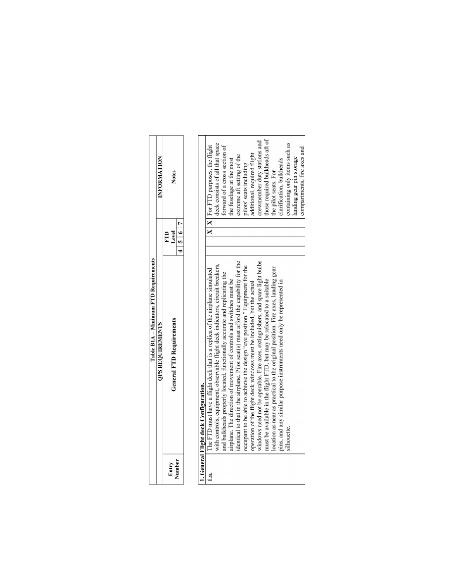
181
Federal Aviation Administration, DOT
Pt. 60, App. B
VerDate Sep<11>2014
14:00 Mar 14, 2024
Jkt 262047
PO 00000
Frm 00191
Fmt 8010
Sfmt 8006
Q:\14\14V2.TXT
PC31
ER09DE22.057</MATH>
aworley on LAPBH6H6L3 with DISTILLER
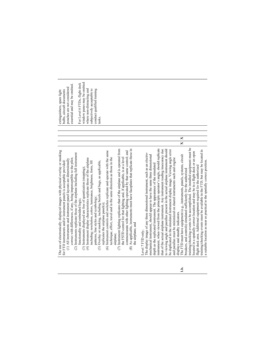
182
14 CFR Ch. I (1–1–24 Edition)
Pt. 60, App. B
VerDate Sep<11>2014
14:00 Mar 14, 2024
Jkt 262047
PO 00000
Frm 00192
Fmt 8010
Sfmt 8006
Q:\14\14V2.TXT
PC31
ER09DE22.058</MATH>
aworley on LAPBH6H6L3 with DISTILLER
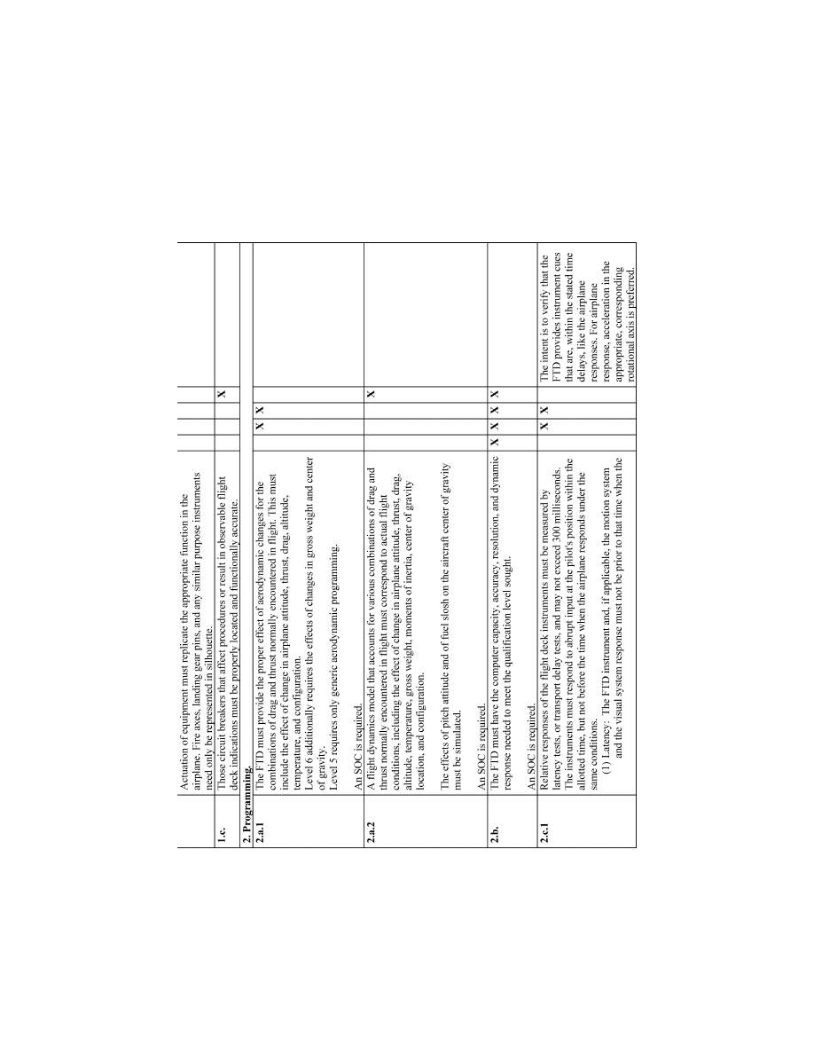
183
Federal Aviation Administration, DOT
Pt. 60, App. B
VerDate Sep<11>2014
14:00 Mar 14, 2024
Jkt 262047
PO 00000
Frm 00193
Fmt 8010
Sfmt 8006
Q:\14\14V2.TXT
PC31
ER09DE22.059</MATH>
aworley on LAPBH6H6L3 with DISTILLER
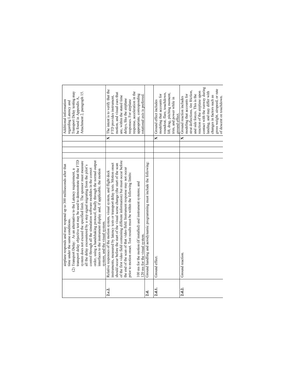
184
14 CFR Ch. I (1–1–24 Edition)
Pt. 60, App. B
VerDate Sep<11>2014
14:00 Mar 14, 2024
Jkt 262047
PO 00000
Frm 00194
Fmt 8010
Sfmt 8006
Q:\14\14V2.TXT
PC31
ER09DE22.060</MATH>
aworley on LAPBH6H6L3 with DISTILLER
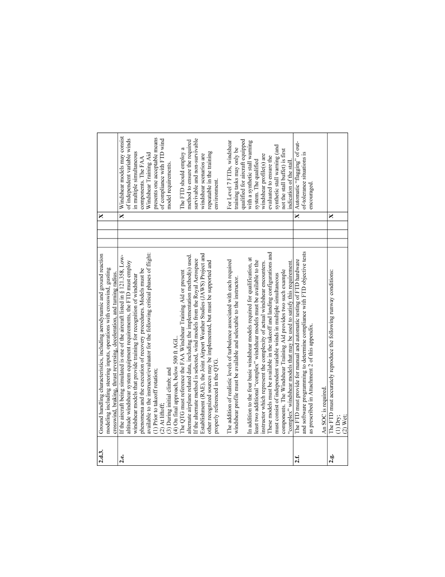
185
Federal Aviation Administration, DOT
Pt. 60, App. B
VerDate Sep<11>2014
14:00 Mar 14, 2024
Jkt 262047
PO 00000
Frm 00195
Fmt 8010
Sfmt 8006
Q:\14\14V2.TXT
PC31
ER09DE22.061</MATH>
aworley on LAPBH6H6L3 with DISTILLER
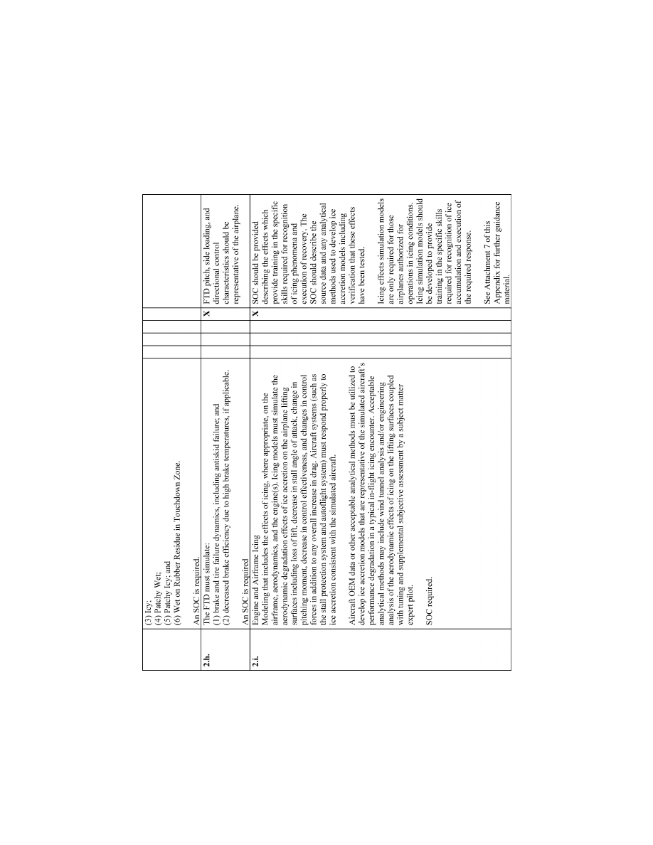
186
14 CFR Ch. I (1–1–24 Edition)
Pt. 60, App. B
VerDate Sep<11>2014
14:00 Mar 14, 2024
Jkt 262047
PO 00000
Frm 00196
Fmt 8010
Sfmt 8006
Q:\14\14V2.TXT
PC31
ER09DE22.062</MATH>
aworley on LAPBH6H6L3 with DISTILLER
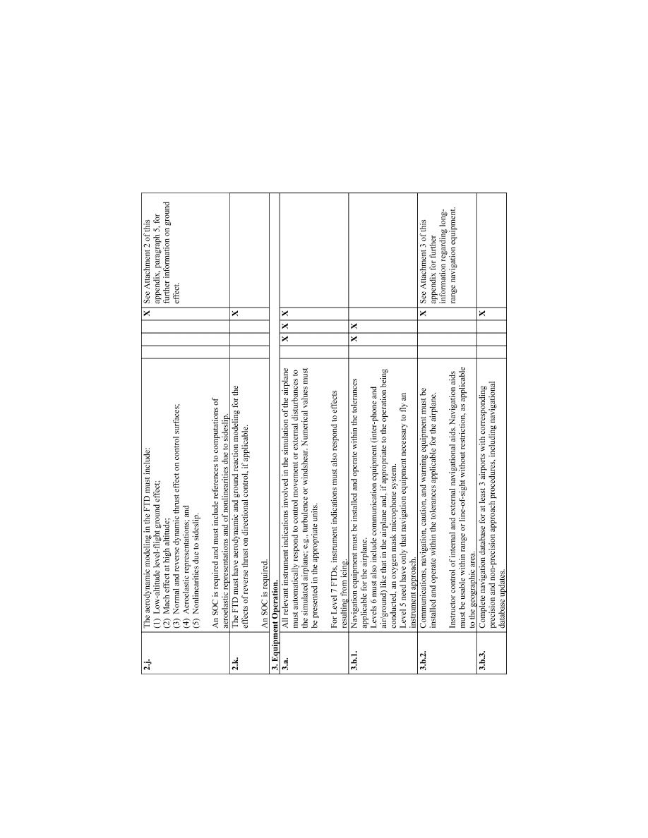
187
Federal Aviation Administration, DOT
Pt. 60, App. B
VerDate Sep<11>2014
14:00 Mar 14, 2024
Jkt 262047
PO 00000
Frm 00197
Fmt 8010
Sfmt 8006
Q:\14\14V2.TXT
PC31
ER09DE22.063</MATH>
aworley on LAPBH6H6L3 with DISTILLER
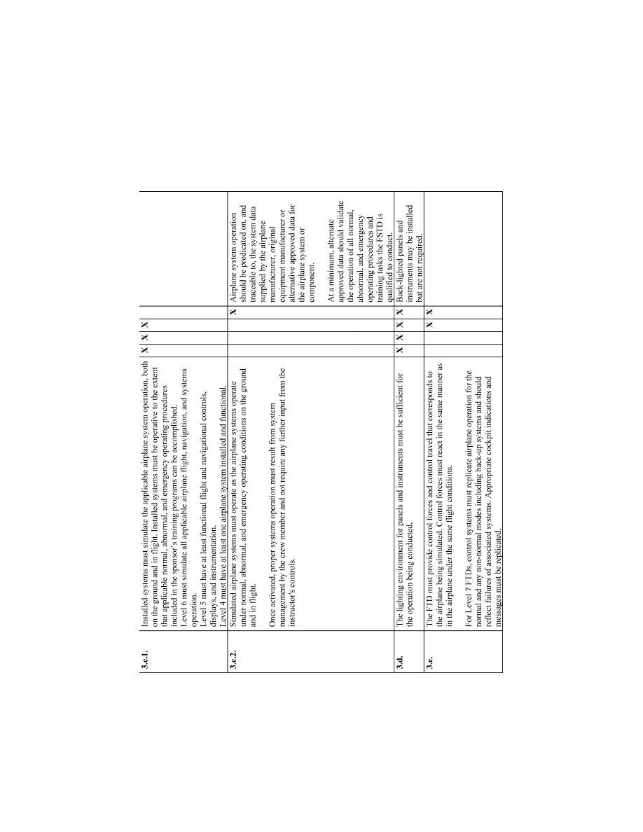
188
14 CFR Ch. I (1–1–24 Edition)
Pt. 60, App. B
VerDate Sep<11>2014
14:00 Mar 14, 2024
Jkt 262047
PO 00000
Frm 00198
Fmt 8010
Sfmt 8006
Q:\14\14V2.TXT
PC31
ER09DE22.064</MATH>
aworley on LAPBH6H6L3 with DISTILLER
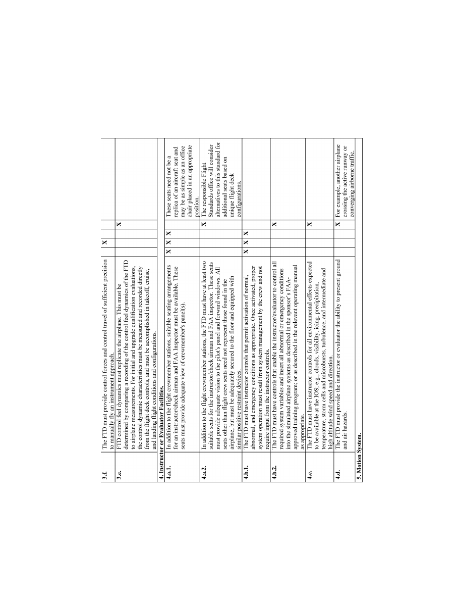
189
Federal Aviation Administration, DOT
Pt. 60, App. B
VerDate Sep<11>2014
14:00 Mar 14, 2024
Jkt 262047
PO 00000
Frm 00199
Fmt 8010
Sfmt 8006
Q:\14\14V2.TXT
PC31
ER09DE22.065</MATH>
aworley on LAPBH6H6L3 with DISTILLER
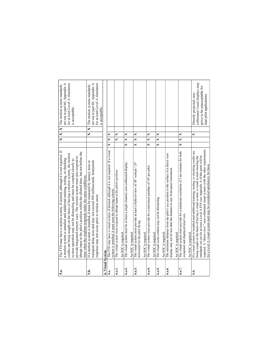
190
14 CFR Ch. I (1–1–24 Edition)
Pt. 60, App. B
VerDate Sep<11>2014
14:00 Mar 14, 2024
Jkt 262047
PO 00000
Frm 00200
Fmt 8010
Sfmt 8006
Q:\14\14V2.TXT
PC31
ER09DE22.066</MATH>
aworley on LAPBH6H6L3 with DISTILLER
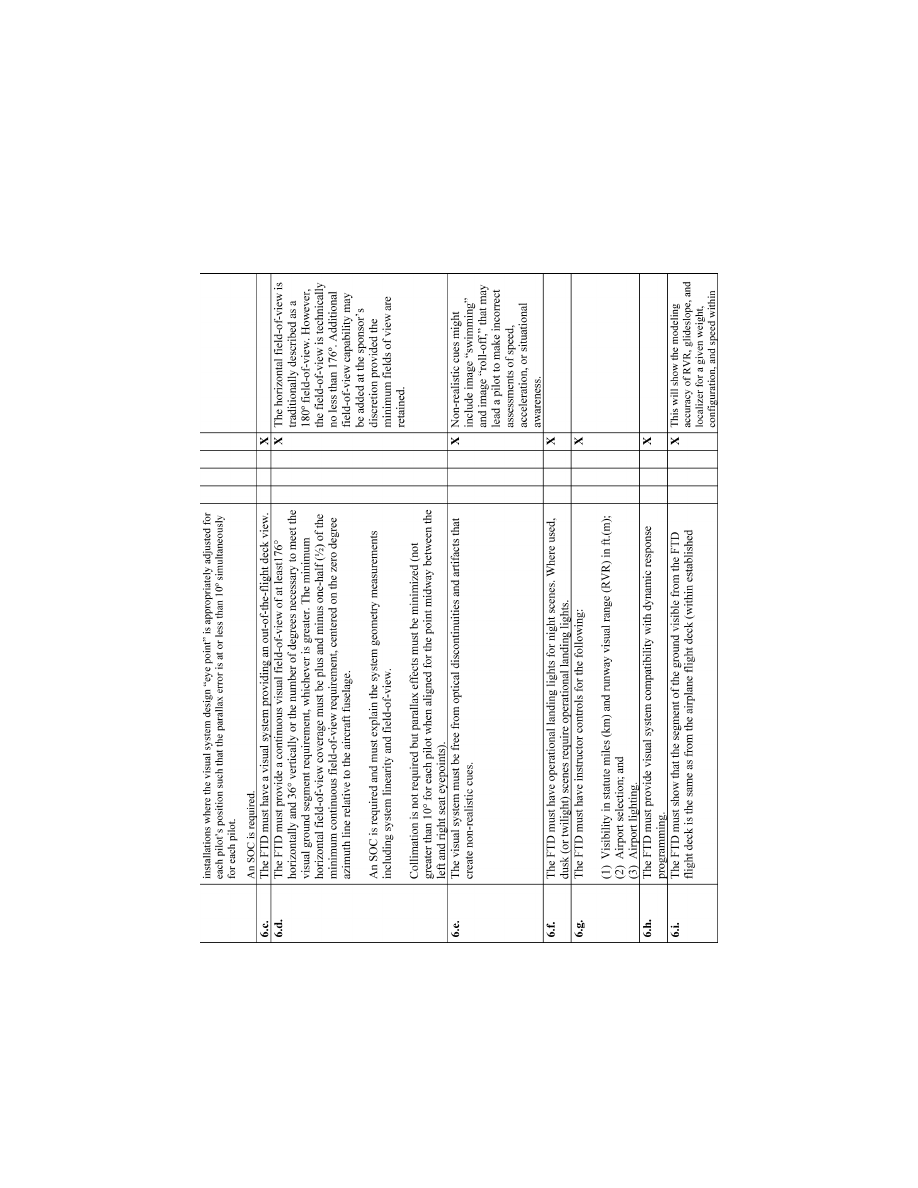
191
Federal Aviation Administration, DOT
Pt. 60, App. B
VerDate Sep<11>2014
14:00 Mar 14, 2024
Jkt 262047
PO 00000
Frm 00201
Fmt 8010
Sfmt 8006
Q:\14\14V2.TXT
PC31
ER09DE22.067</MATH>
aworley on LAPBH6H6L3 with DISTILLER
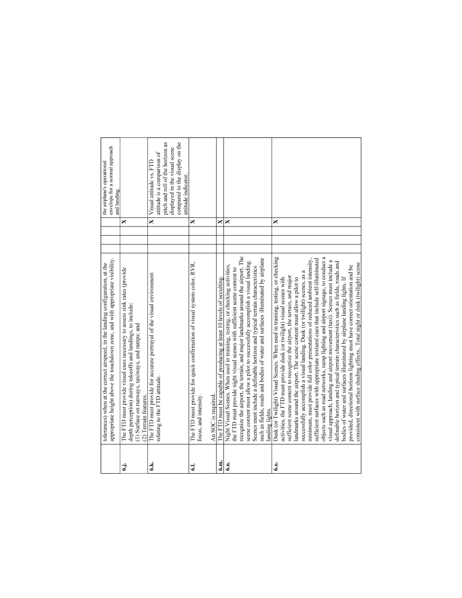
192
14 CFR Ch. I (1–1–24 Edition)
Pt. 60, App. B
VerDate Sep<11>2014
14:00 Mar 14, 2024
Jkt 262047
PO 00000
Frm 00202
Fmt 8010
Sfmt 8006
Q:\14\14V2.TXT
PC31
ER09DE22.068</MATH>
aworley on LAPBH6H6L3 with DISTILLER
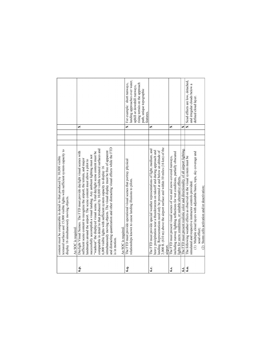
193
Federal Aviation Administration, DOT
Pt. 60, App. B
VerDate Sep<11>2014
14:00 Mar 14, 2024
Jkt 262047
PO 00000
Frm 00203
Fmt 8010
Sfmt 8006
Q:\14\14V2.TXT
PC31
ER09DE22.069</MATH>
aworley on LAPBH6H6L3 with DISTILLER
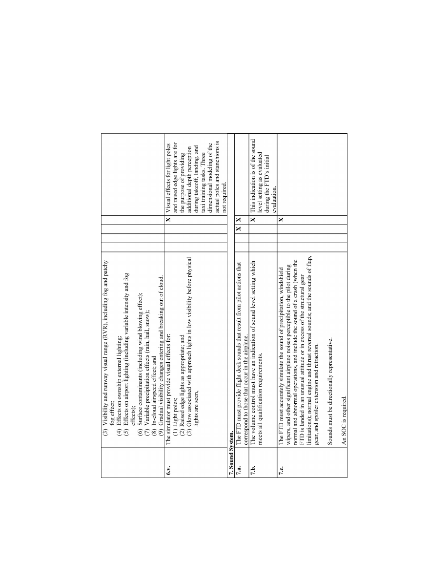
194
14 CFR Ch. I (1–1–24 Edition)
Pt. 60, App. B
VerDate Sep<11>2014
14:00 Mar 14, 2024
Jkt 262047
PO 00000
Frm 00204
Fmt 8010
Sfmt 8006
Q:\14\14V2.TXT
PC31
ER09DE22.070</MATH>
aworley on LAPBH6H6L3 with DISTILLER
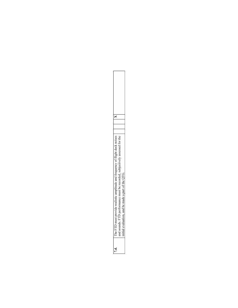
195
Federal Aviation Administration, DOT
Pt. 60, App. B
VerDate Sep<11>2014
14:00 Mar 14, 2024
Jkt 262047
PO 00000
Frm 00205
Fmt 8010
Sfmt 8006
Q:\14\14V2.TXT
PC31
ER09DE22.071</MATH>
aworley on LAPBH6H6L3 with DISTILLER
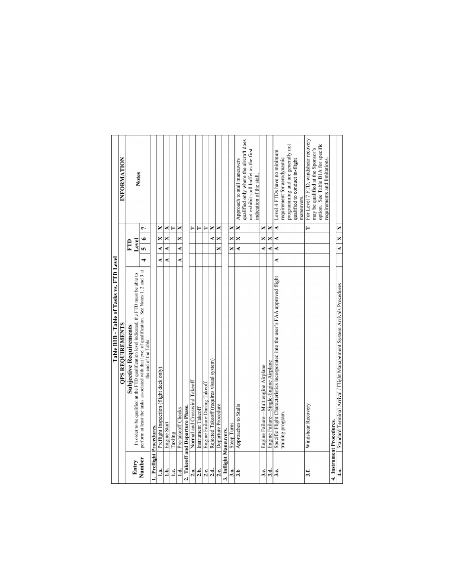
196
14 CFR Ch. I (1–1–24 Edition)
Pt. 60, App. B
VerDate Sep<11>2014
14:00 Mar 14, 2024
Jkt 262047
PO 00000
Frm 00206
Fmt 8010
Sfmt 8006
Q:\14\14V2.TXT
PC31
ER20MY16.091</GPH>
aworley on LAPBH6H6L3 with DISTILLER
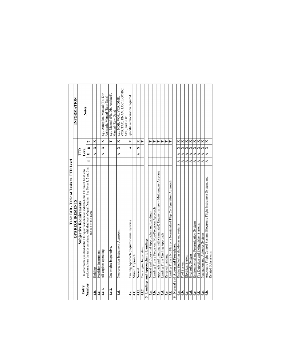
197
Federal Aviation Administration, DOT
Pt. 60, App. B
VerDate Sep<11>2014
14:00 Mar 14, 2024
Jkt 262047
PO 00000
Frm 00207
Fmt 8010
Sfmt 8006
Q:\14\14V2.TXT
PC31
ER20MY16.092</GPH>
aworley on LAPBH6H6L3 with DISTILLER
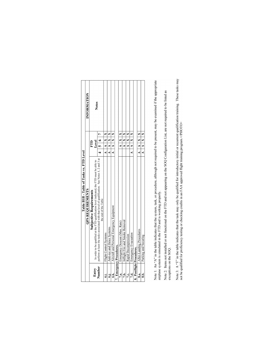
198
14 CFR Ch. I (1–1–24 Edition)
Pt. 60, App. B
VerDate Sep<11>2014
14:00 Mar 14, 2024
Jkt 262047
PO 00000
Frm 00208
Fmt 8010
Sfmt 8006
Q:\14\14V2.TXT
PC31
ER20MY16.093</GPH>
aworley on LAPBH6H6L3 with DISTILLER
199
Federal Aviation Administration, DOT
Pt. 60, App. B
T
ABLE
B1C—T
ABLE OF
FTD S
YSTEM
T
ASKS
QPS
REQUIREMENTS
QPS Requirements
Information
Entry No.
Subjective Requirements
In order to be qualified at the FTD qualification
level indicated, the FTD must be able to per-
form at least the tasks associated with that level
of qualification.
FTD level
Notes
4 5 6
1. Instructor Operating Station (IOS).
1.a. .............
Power
switch(es) .................................................
X X X
1.b. .............
Airplane conditions ..............................................
A
X
X e.g., GW, CG, Fuel loading, Systems, Ground
Crew.
1.c. .............
Airports/Runways ................................................
X
X
X e.g., Selection and Presets; Surface and Light-
ing controls if equipped with a visual system.
1.d. .............
Environmental controls ........................................
X
X
X
e.g., Temp, Wind.
1.e. .............
Airplane system malfunctions (Insertion/deletion)
A
X
X
1.f. .............
Locks, Freezes, and Repositioning .....................
X
X
X
1.g. .............
Sound Controls. (On/off/adjustment) ...................
X
X
X
1.h. .............
Motion/Control Loading System, as appropriate.
On/off/emergency stop.
A A A
2. Observer Seats/Stations.
2.a. .............
Position/Adjustment/Positive restraint system ....
X
X
X
Note 1: An ‘‘A’’ in the table indicates that the system, task, or procedure, although not required to be present, may be exam-
ined if the appropriate system is in the FTD and is working properly.
A
TTACHMENT
2
TO
A
PPENDIX
B
TO
P
ART
60—
F
LIGHT
T
RAINING
D
EVICE
(FTD) O
BJECTIVE
T
ESTS
llllllllllllllllllllllll
B
EGIN
I
NFORMATION
1. D
ISCUSSION
a. For the purposes of this attachment, the
flight conditions specified in the Flight Con-
ditions Column of Table B2A, are defined as
follows:
(1) Ground—on ground, independent of air-
plane configuration;
(2) Take-off—gear down with flaps/slats in
any certified takeoff position;
(3) First segment climb—gear down with
flaps/slats in any certified takeoff position
(normally not above 50 ft AGL);
(4) Second segment climb—gear up with
flaps/slats in any certified takeoff position
(normally between 50 ft and 400 ft AGL);
(5) Clean—flaps/slats retracted and gear up;
(6) Cruise—clean configuration at cruise
altitude and airspeed;
(7) Approach—gear up or down with flaps/
slats at any normal approach position as rec-
ommended by the airplane manufacturer;
and
(8) Landing—gear down with flaps/slats in
any certified landing position.
b. The format for numbering the objective
tests in Appendix A, Attachment 2, Table
A2A, and the objective tests in Appendix B,
Attachment 2, Table B2A, is identical. How-
ever, each test required for FFSs is not nec-
essarily required for FTDs. Also, each test
required for FTDs is not necessarily required
for FFSs. Therefore, when a test number (or
series of numbers) is not required, the term
‘‘Reserved’’ is used in the table at that loca-
tion. Following this numbering format pro-
vides a degree of commonality between the
two tables and substantially reduces the po-
tential for confusion when referring to objec-
tive test numbers for either FFSs or FTDs.
c. The reader is encouraged to review the
Airplane Flight Simulator Evaluation Hand-
book, Volumes I and II, published by the
Royal Aeronautical Society, London, UK,
and FAA AC 25–7, as amended, Flight Test
Guide for Certification of Transport Cat-
egory Airplanes, and AC 23–8, as amended,
Flight Test Guide for Certification of Part 23
Airplanes, for references and examples re-
garding flight testing requirements and tech-
niques.
d. If relevant winds are present in the ob-
jective data, the wind vector should be clear-
ly noted as part of the data presentation, ex-
pressed in conventional terminology, and re-
lated to the runway being used for the test.
e. A Level 4 FTD does not require objective
tests and therefore, Level 4 is not addressed
in the following table.
VerDate Sep<11>2014
14:00 Mar 14, 2024
Jkt 262047
PO 00000
Frm 00209
Fmt 8010
Sfmt 8002
Q:\14\14V2.TXT
PC31
aworley on LAPBH6H6L3 with DISTILLER

200
14 CFR Ch. I (1–1–24 Edition)
Pt. 60, App. B
E
ND
I
NFORMATION
llllllllllllllllllllllll
B
EGIN
QPS R
EQUIREMENTS
2. T
EST
R
EQUIREMENTS
a. The ground and flight tests required for
qualification are listed in Table B2A Objec-
tive Tests. Computer generated FTD test re-
sults must be provided for each test except
where an alternate test is specifically au-
thorized by the responsible Flight Standards
office. If a flight condition or operating con-
dition is required for the test but does not
apply to the airplane being simulated or to
the qualification level sought, it may be dis-
regarded (e.g., an engine out missed ap-
proach for a single-engine airplane; a maneu-
ver using reverse thrust for an airplane with-
out reverse thrust capability). Each test re-
sult is compared against the validation data
described in § 60.13, and in Appendix B. The
results must be produced on an appropriate
recording device acceptable to the respon-
sible Flight Standards office and must in-
clude FTD number, date, time, conditions,
tolerances, and appropriate dependent vari-
ables portrayed in comparison to the valida-
tion data. Time histories are required unless
otherwise indicated in Table B2A. All results
must be labeled using the tolerances and
units given.
b. Table B2A in this attachment sets out
the test results required, including the pa-
rameters, tolerances, and flight conditions
for FTD validation. Tolerances are provided
for the listed tests because mathematical
modeling and acquisition and development of
reference data are often inexact. All toler-
ances listed in the following tables are ap-
plied to FTD performance. When two toler-
ance values are given for a parameter, the
less restrictive may be used unless otherwise
indicated. In those cases where a tolerance is
expressed only as a percentage, the tolerance
percentage applies to the maximum value of
that parameter within its normal operating
range as measured from the neutral or zero
position unless otherwise indicated.
c. Certain tests included in this attach-
ment must be supported with a SOC. In
Table B2A, requirements for SOCs are indi-
cated in the ‘‘Test Details’’ column.
d. When operational or engineering judg-
ment is used in making assessments for
flight test data applications for FTD valid-
ity, such judgment may not be limited to a
single parameter. For example, data that ex-
hibit rapid variations of the measured pa-
rameters may require interpolations or a
‘‘best fit’’ data section. All relevant param-
eters related to a given maneuver or flight
condition must be provided to allow overall
interpretation. When it is difficult or impos-
sible to match FTD to airplane data
throughout a time history, differences must
be justified by providing a comparison of
other related variables for the condition
being assessed.
e. It is not acceptable to program the FTD
so that the mathematical modeling is cor-
rect only at the validation test points. Un-
less otherwise noted, FTD tests must rep-
resent airplane performance and handling
qualities at operating weights and centers of
gravity (CG) typical of normal operation.
FTD tests at extreme weight or CG condi-
tions may be acceptable where required for
concurrent aircraft certification testing.
Tests of handling qualities must include val-
idation of augmentation devices.
f. When comparing the parameters listed to
those of the airplane, sufficient data must
also be provided to verify the correct flight
condition and airplane configuration
changes. For example, to show that control
force is within the parameters for a static
stability test, data to show the correct air-
speed, power, thrust or torque, airplane con-
figuration, altitude, and other appropriate
datum identification parameters must also
be given. If comparing short period dynam-
ics, normal acceleration may be used to es-
tablish a match to the airplane, but airspeed,
altitude, control input, airplane configura-
tion, and other appropriate data must also
be given. If comparing landing gear change
dynamics, pitch, airspeed, and altitude may
be used to establish a match to the airplane,
but landing gear position must also be pro-
vided. All airspeed values must be properly
annotated (e.g., indicated versus calibrated).
In addition, the same variables must be used
for comparison (e.g., compare inches to
inches rather than inches to centimeters).
g. The QTG provided by the sponsor must
clearly describe how the FTD will be set up
and operated for each test. Each FTD sub-
system may be tested independently, but
overall integrated testing of the FTD must
be accomplished to assure that the total
FTD system meets the prescribed standards.
A manual test procedure with explicit and
detailed steps for completing each test must
also be provided.
h. For previously qualified FTDs, the tests
and tolerances of this attachment may be
used in subsequent continuing qualification
evaluations for any given test if the sponsor
has submitted a proposed MQTG revision to
the responsible Flight Standards office and
has received responsible Flight Standards of-
fice approval.
i. FTDs are evaluated and qualified with an
engine model simulating the airplane data
supplier’s flight test engine. For qualifica-
tion of alternative engine models (either
variations of the flight test engines or other
manufacturer’s engines) additional tests
with the alternative engine models may be
required. This attachment contains guide-
lines for alternative engines.
VerDate Sep<11>2014
14:00 Mar 14, 2024
Jkt 262047
PO 00000
Frm 00210
Fmt 8010
Sfmt 8002
Q:\14\14V2.TXT
PC31
aworley on LAPBH6H6L3 with DISTILLER

201
Federal Aviation Administration, DOT
Pt. 60, App. B
j. Testing Computer Controlled Aircraft
(CCA) simulators, or other highly augmented
airplane simulators, flight test data is re-
quired for the Normal (N) and/or Non-normal
(NN) control states, as indicated in this at-
tachment. Where test results are inde-
pendent of control state, Normal or Non-nor-
mal control data may be used. All tests in
Table B2A require test results in the Normal
control state unless specifically noted other-
wise in the Test Details section following the
CCA designation. The responsible Flight
Standards office will determine what tests
are appropriate for airplane simulation data.
When making this determination, the re-
sponsible Flight Standards office may re-
quire other levels of control state degrada-
tion for specific airplane tests. Where Non-
normal control states are required, test data
must be provided for one or more Non-nor-
mal control states, and must include the
least augmented state. Where applicable,
flight test data must record Normal and
Non-normal states for:
(1) Pilot controller deflections or electroni-
cally generated inputs, including location of
input; and
(2) Flight control surface positions unless
test results are not affected by, or are inde-
pendent of, surface positions.
k. Tests of handling qualities must include
validation of augmentation devices. FTDs
for highly augmented airplanes will be vali-
dated both in the unaugmented configura-
tion (or failure state with the maximum per-
mitted degradation in handling qualities)
and the augmented configuration. Where
various levels of handling qualities result
from failure states, validation of the effect
of the failure is necessary. Requirements for
testing will be mutually agreed to between
the sponsor and the responsible Flight
Standards office on a case-by-case basis.
l. Some tests will not be required for air-
planes using airplane hardware in the FTD
flight deck (e.g., ‘‘side stick controller’’).
These exceptions are noted in Section 2
‘‘Handling Qualities’’ in Table B2A of this at-
tachment. However, in these cases, the spon-
sor must provide a statement that the air-
plane hardware meets the appropriate manu-
facturer’s specifications and the sponsor
must have supporting information to that
fact available for responsible Flight Stand-
ards office review.
m. For objective test purposes, see Appen-
dix F of this part for the definitions of ‘‘Near
maximum,’’ ‘‘Light,’’ and ‘‘Medium’’ gross
weight.
E
ND
QPS R
EQUIREMENTS
llllllllllllllllllllllll
B
EGIN
I
NFORMATION
n. In those cases where the objective test
results authorize a ‘‘snapshot test’’ or a ‘‘se-
ries of snapshot test results’’ in lieu of a
time-history result, the sponsor or other
data provider must ensure that a steady
state condition exists at the instant of time
captured by the ‘‘snapshot.’’ The steady
state condition must exist from 4 seconds
prior to, through 1 second following, the in-
stant of time captured by the snap shot.
o. Refer to AC 120–27, ‘‘Aircraft Weight and
Balance’’ and FAA–H–8083–1, ‘‘Aircraft
Weight and Balance Handbook’’ for more in-
formation.
E
ND
I
NFORMATION
llllllllllllllllllllllll
VerDate Sep<11>2014
14:00 Mar 14, 2024
Jkt 262047
PO 00000
Frm 00211
Fmt 8010
Sfmt 8002
Q:\14\14V2.TXT
PC31
aworley on LAPBH6H6L3 with DISTILLER
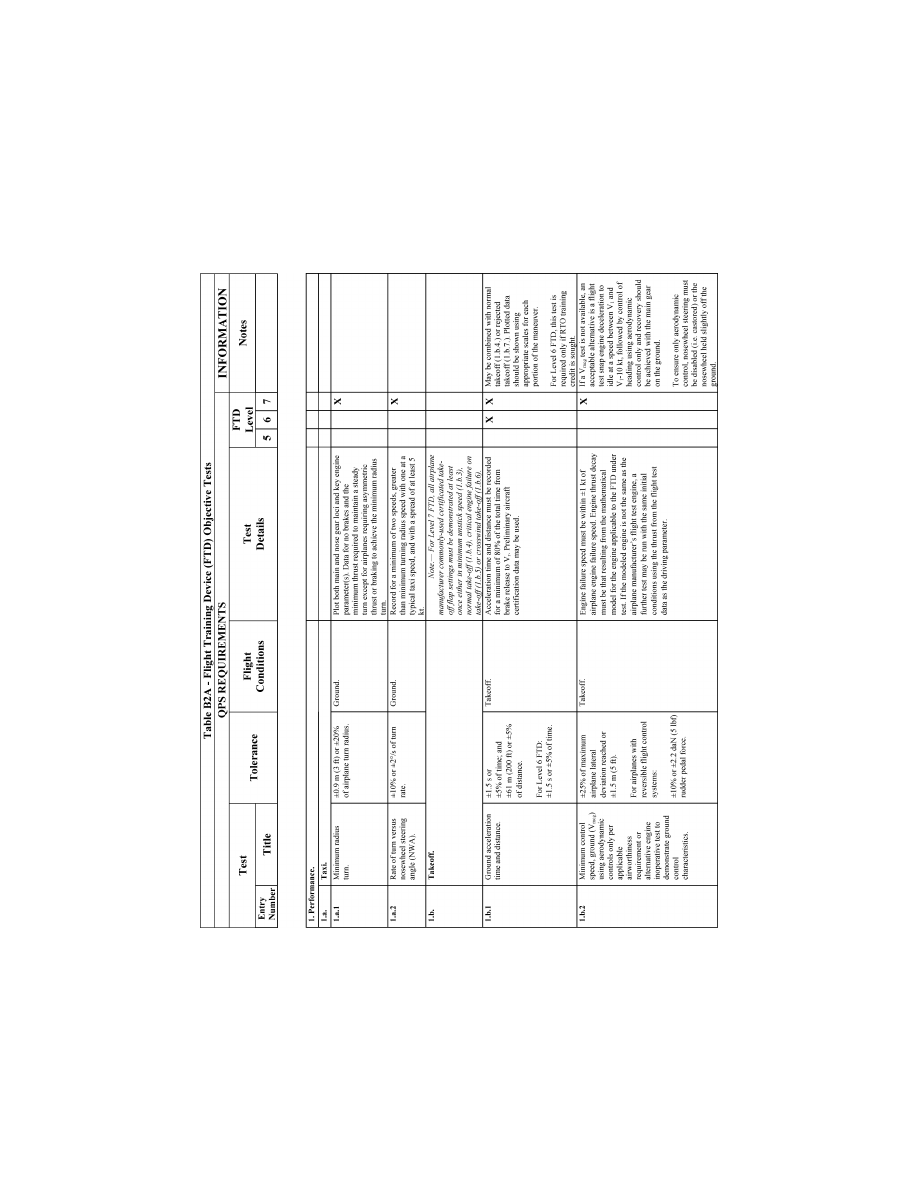
202
14 CFR Ch. I (1–1–24 Edition)
Pt. 60, App. B
VerDate Sep<11>2014
14:00 Mar 14, 2024
Jkt 262047
PO 00000
Frm 00212
Fmt 8010
Sfmt 8006
Q:\14\14V2.TXT
PC31
ER09DE22.072</GPH>
aworley on LAPBH6H6L3 with DISTILLER

203
Federal Aviation Administration, DOT
Pt. 60, App. B
VerDate Sep<11>2014
14:00 Mar 14, 2024
Jkt 262047
PO 00000
Frm 00213
Fmt 8010
Sfmt 8006
Q:\14\14V2.TXT
PC31
ER09DE22.073</GPH>
aworley on LAPBH6H6L3 with DISTILLER
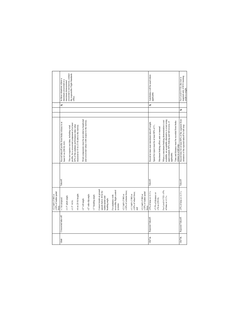
204
14 CFR Ch. I (1–1–24 Edition)
Pt. 60, App. B
VerDate Sep<11>2014
14:00 Mar 14, 2024
Jkt 262047
PO 00000
Frm 00214
Fmt 8010
Sfmt 8006
Q:\14\14V2.TXT
PC31
ER09DE22.074</GPH>
aworley on LAPBH6H6L3 with DISTILLER
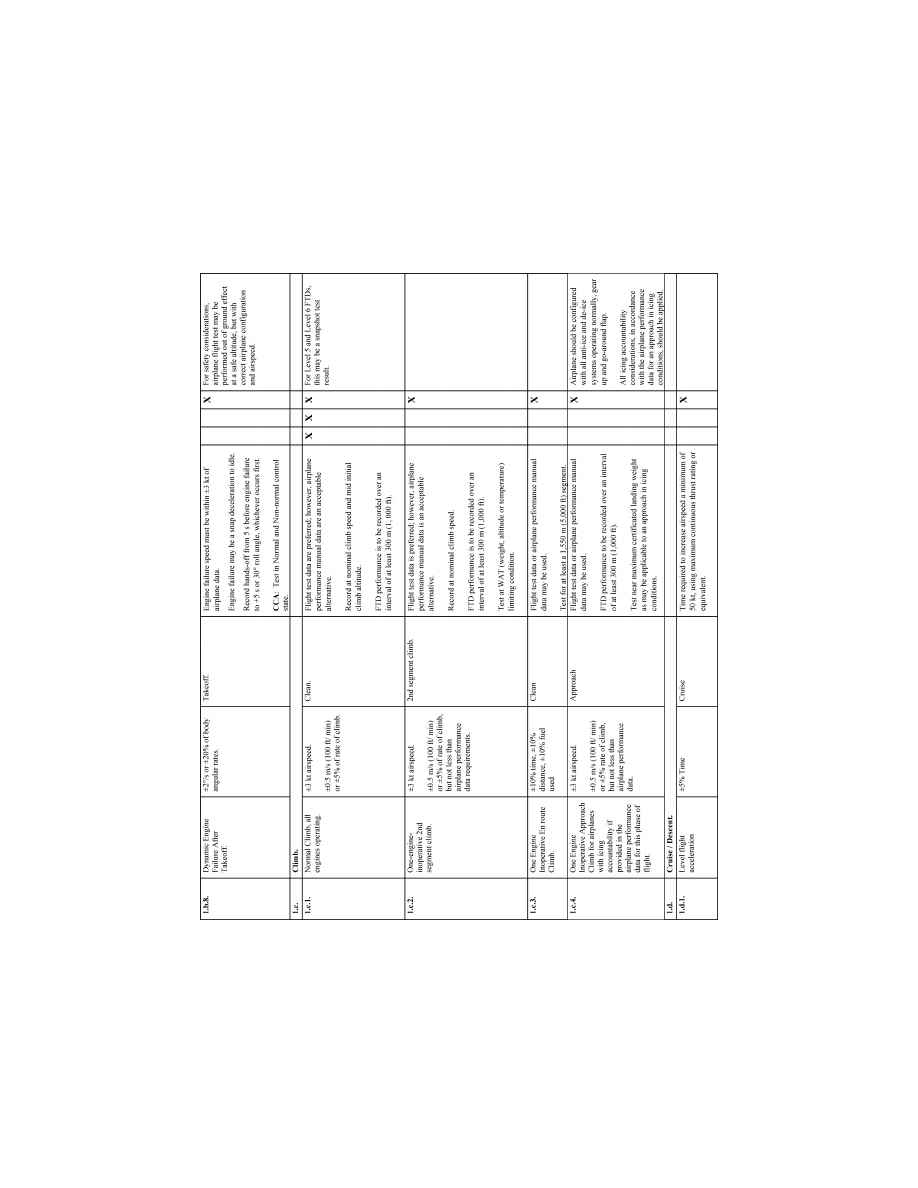
205
Federal Aviation Administration, DOT
Pt. 60, App. B
VerDate Sep<11>2014
14:00 Mar 14, 2024
Jkt 262047
PO 00000
Frm 00215
Fmt 8010
Sfmt 8006
Q:\14\14V2.TXT
PC31
ER09DE22.075</GPH>
aworley on LAPBH6H6L3 with DISTILLER
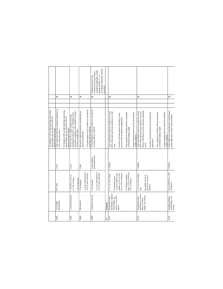
206
14 CFR Ch. I (1–1–24 Edition)
Pt. 60, App. B
VerDate Sep<11>2014
14:00 Mar 14, 2024
Jkt 262047
PO 00000
Frm 00216
Fmt 8010
Sfmt 8006
Q:\14\14V2.TXT
PC31
ER09DE22.076</GPH>
aworley on LAPBH6H6L3 with DISTILLER
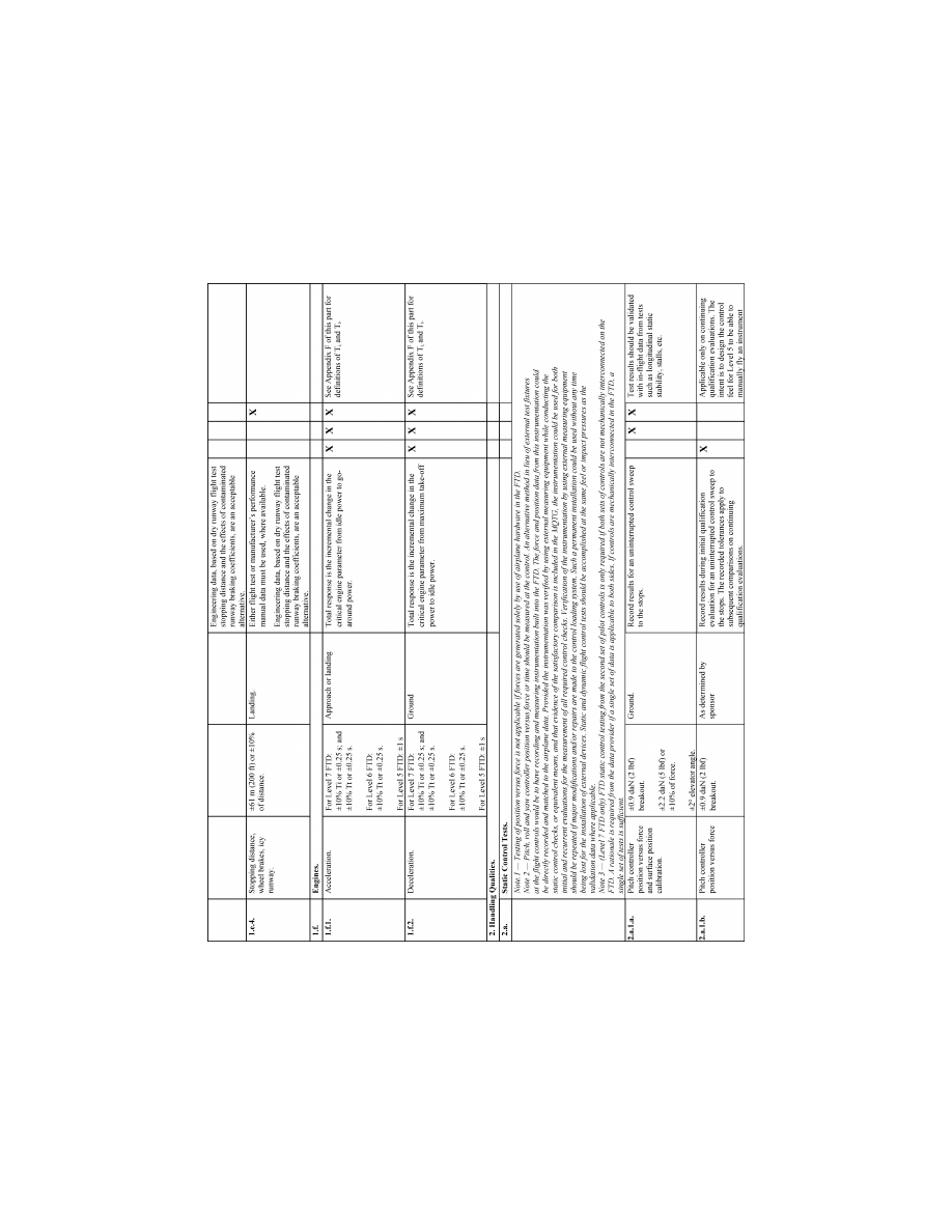
207
Federal Aviation Administration, DOT
Pt. 60, App. B
VerDate Sep<11>2014
14:00 Mar 14, 2024
Jkt 262047
PO 00000
Frm 00217
Fmt 8010
Sfmt 8006
Q:\14\14V2.TXT
PC31
ER09DE22.077</GPH>
aworley on LAPBH6H6L3 with DISTILLER
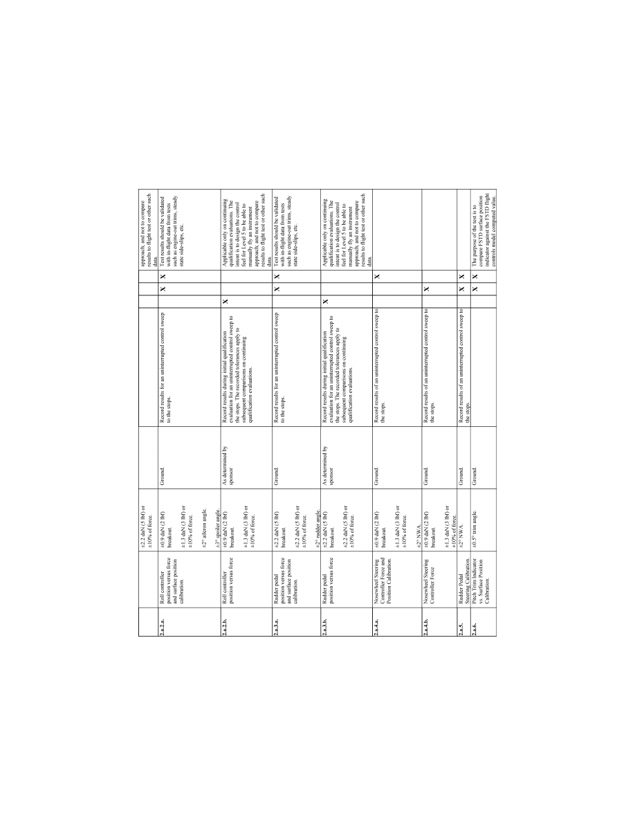
208
14 CFR Ch. I (1–1–24 Edition)
Pt. 60, App. B
VerDate Sep<11>2014
14:00 Mar 14, 2024
Jkt 262047
PO 00000
Frm 00218
Fmt 8010
Sfmt 8006
Q:\14\14V2.TXT
PC31
ER09DE22.078</GPH>
aworley on LAPBH6H6L3 with DISTILLER
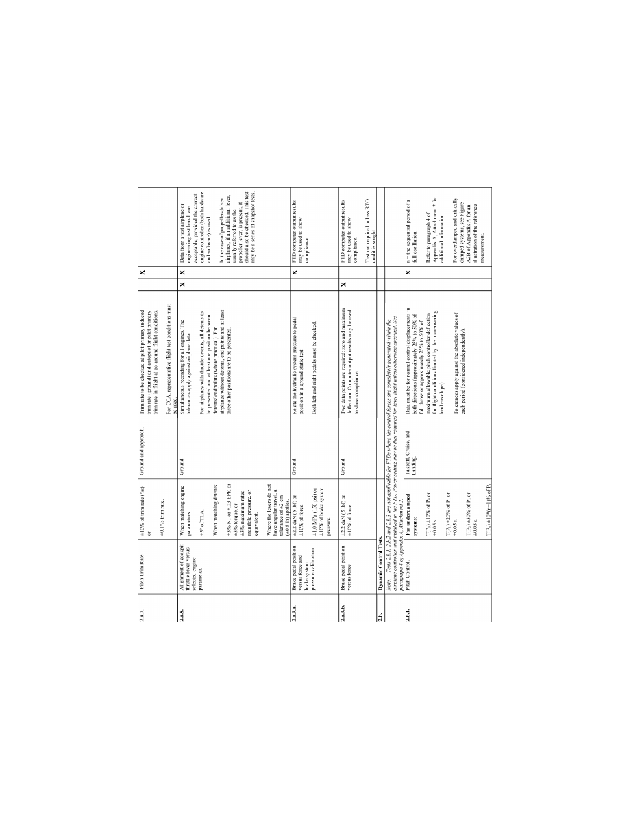
209
Federal Aviation Administration, DOT
Pt. 60, App. B
VerDate Sep<11>2014
14:00 Mar 14, 2024
Jkt 262047
PO 00000
Frm 00219
Fmt 8010
Sfmt 8006
Q:\14\14V2.TXT
PC31
ER09DE22.079</GPH>
aworley on LAPBH6H6L3 with DISTILLER
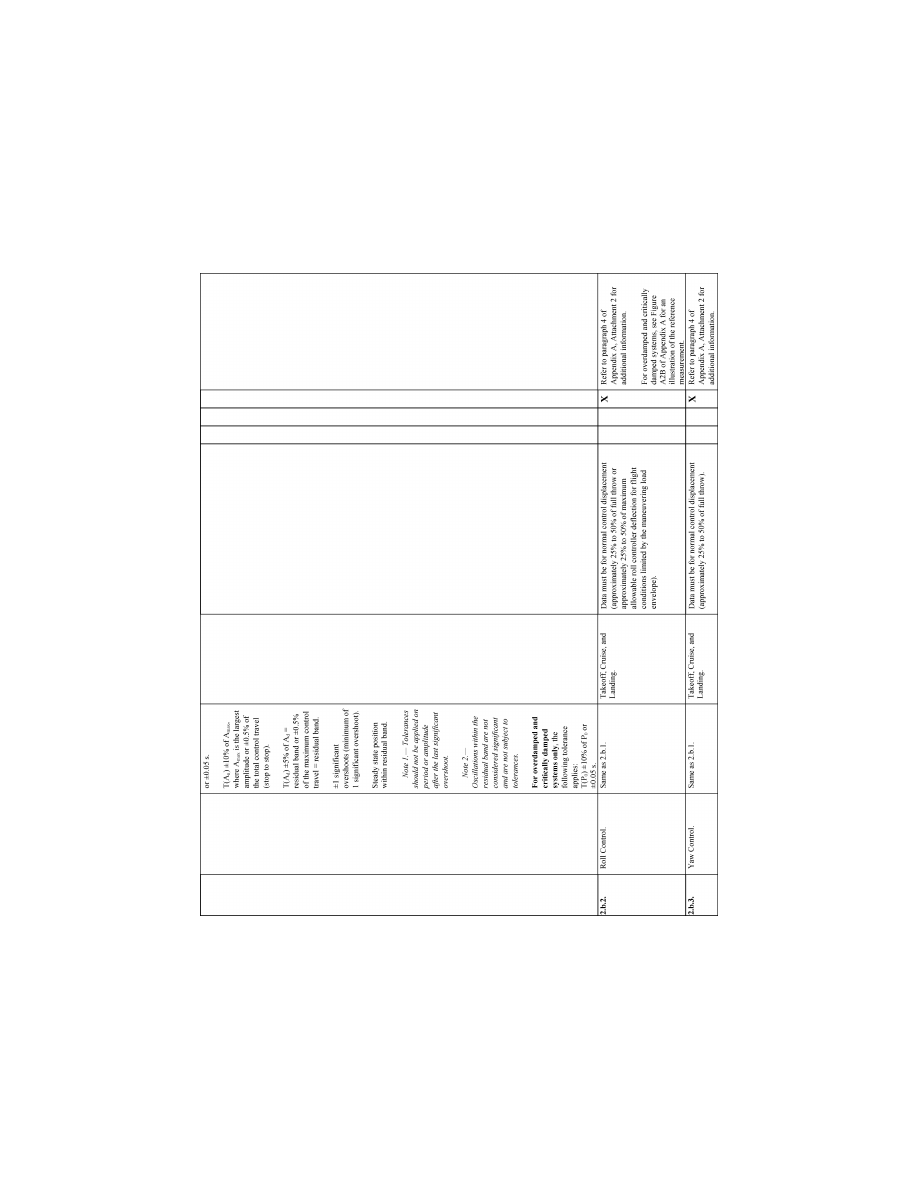
210
14 CFR Ch. I (1–1–24 Edition)
Pt. 60, App. B
VerDate Sep<11>2014
14:00 Mar 14, 2024
Jkt 262047
PO 00000
Frm 00220
Fmt 8010
Sfmt 8006
Q:\14\14V2.TXT
PC31
ER09DE22.080</GPH>
aworley on LAPBH6H6L3 with DISTILLER
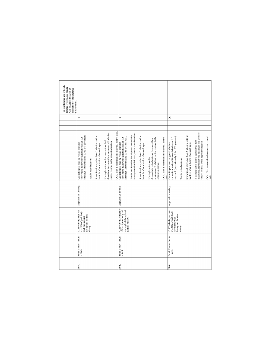
211
Federal Aviation Administration, DOT
Pt. 60, App. B
VerDate Sep<11>2014
14:00 Mar 14, 2024
Jkt 262047
PO 00000
Frm 00221
Fmt 8010
Sfmt 8006
Q:\14\14V2.TXT
PC31
ER09DE22.081</GPH>
aworley on LAPBH6H6L3 with DISTILLER
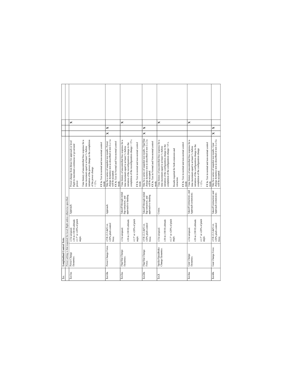
212
14 CFR Ch. I (1–1–24 Edition)
Pt. 60, App. B
VerDate Sep<11>2014
14:00 Mar 14, 2024
Jkt 262047
PO 00000
Frm 00222
Fmt 8010
Sfmt 8006
Q:\14\14V2.TXT
PC31
ER09DE22.082</GPH>
aworley on LAPBH6H6L3 with DISTILLER
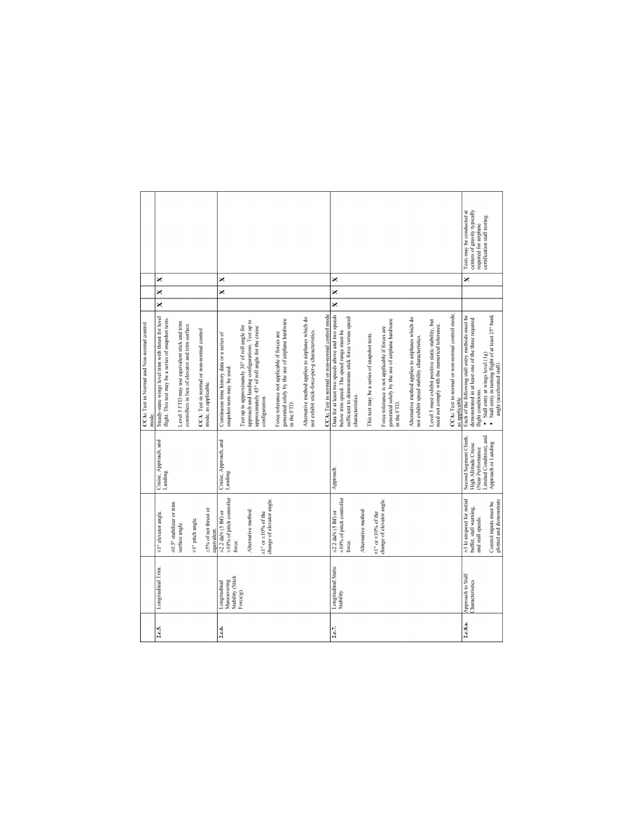
213
Federal Aviation Administration, DOT
Pt. 60, App. B
VerDate Sep<11>2014
14:00 Mar 14, 2024
Jkt 262047
PO 00000
Frm 00223
Fmt 8010
Sfmt 8006
Q:\14\14V2.TXT
PC31
ER09DE22.083</GPH>
aworley on LAPBH6H6L3 with DISTILLER
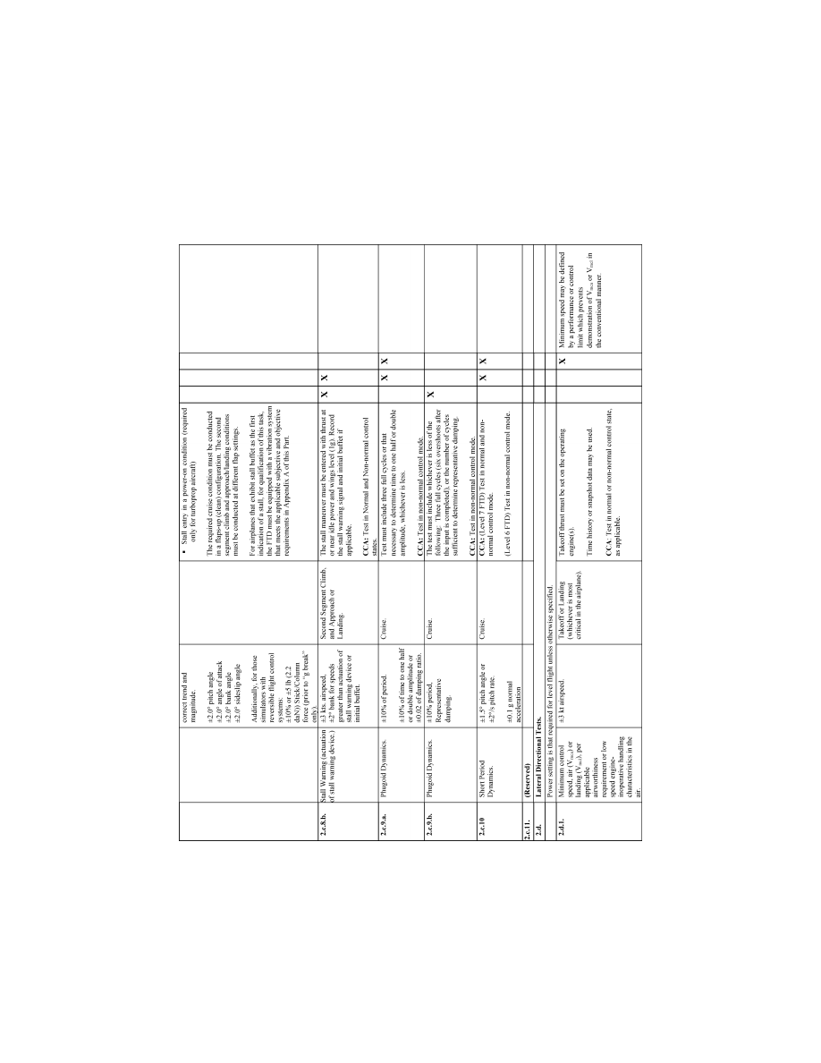
214
14 CFR Ch. I (1–1–24 Edition)
Pt. 60, App. B
VerDate Sep<11>2014
14:00 Mar 14, 2024
Jkt 262047
PO 00000
Frm 00224
Fmt 8010
Sfmt 8006
Q:\14\14V2.TXT
PC31
ER09DE22.084</GPH>
aworley on LAPBH6H6L3 with DISTILLER
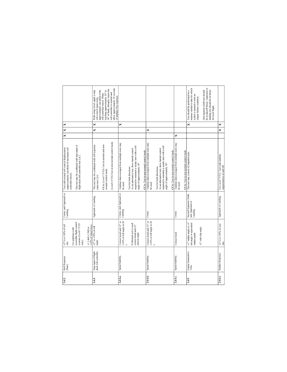
215
Federal Aviation Administration, DOT
Pt. 60, App. B
VerDate Sep<11>2014
14:00 Mar 14, 2024
Jkt 262047
PO 00000
Frm 00225
Fmt 8010
Sfmt 8006
Q:\14\14V2.TXT
PC31
ER09DE22.085</GPH>
aworley on LAPBH6H6L3 with DISTILLER
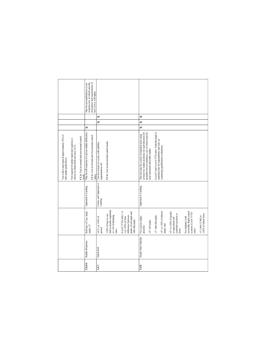
216
14 CFR Ch. I (1–1–24 Edition)
Pt. 60, App. B
VerDate Sep<11>2014
14:00 Mar 14, 2024
Jkt 262047
PO 00000
Frm 00226
Fmt 8010
Sfmt 8006
Q:\14\14V2.TXT
PC31
ER09DE22.086</GPH>
aworley on LAPBH6H6L3 with DISTILLER
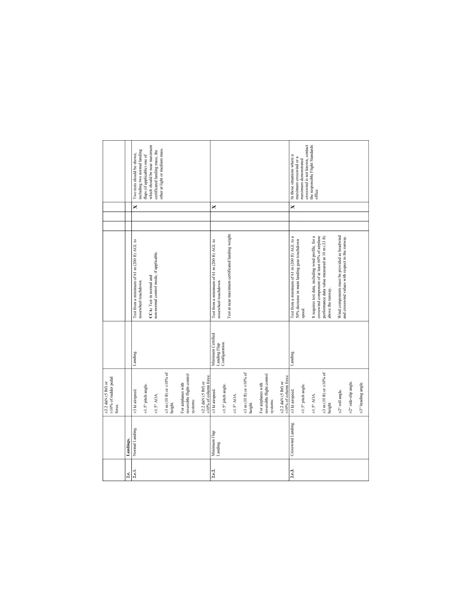
217
Federal Aviation Administration, DOT
Pt. 60, App. B
VerDate Sep<11>2014
14:00 Mar 14, 2024
Jkt 262047
PO 00000
Frm 00227
Fmt 8010
Sfmt 8006
Q:\14\14V2.TXT
PC31
ER09DE22.087</GPH>
aworley on LAPBH6H6L3 with DISTILLER
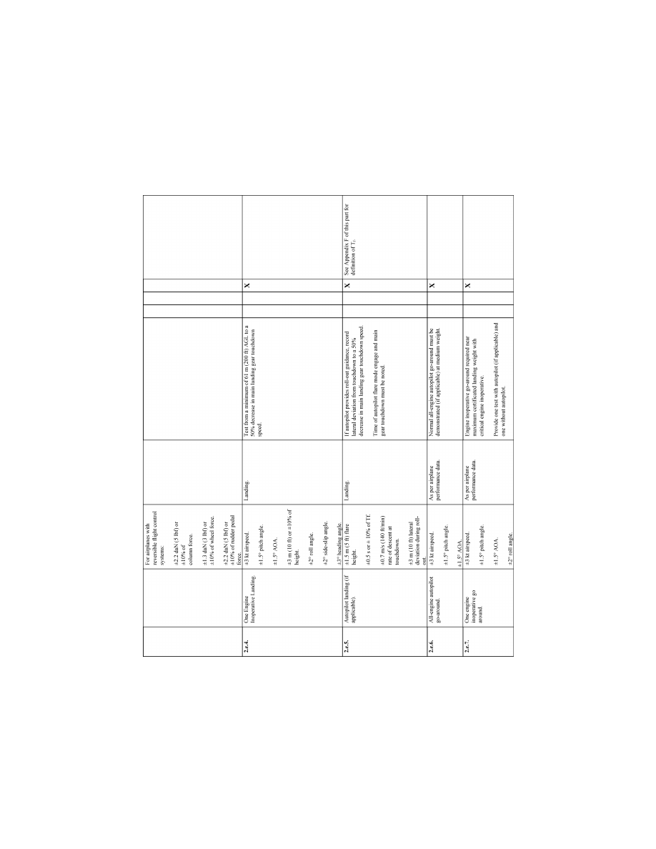
218
14 CFR Ch. I (1–1–24 Edition)
Pt. 60, App. B
VerDate Sep<11>2014
14:00 Mar 14, 2024
Jkt 262047
PO 00000
Frm 00228
Fmt 8010
Sfmt 8006
Q:\14\14V2.TXT
PC31
ER09DE22.088</GPH>
aworley on LAPBH6H6L3 with DISTILLER
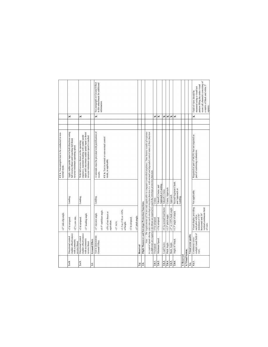
219
Federal Aviation Administration, DOT
Pt. 60, App. B
VerDate Sep<11>2014
14:00 Mar 14, 2024
Jkt 262047
PO 00000
Frm 00229
Fmt 8010
Sfmt 8006
Q:\14\14V2.TXT
PC31
ER09DE22.089</GPH>
aworley on LAPBH6H6L3 with DISTILLER
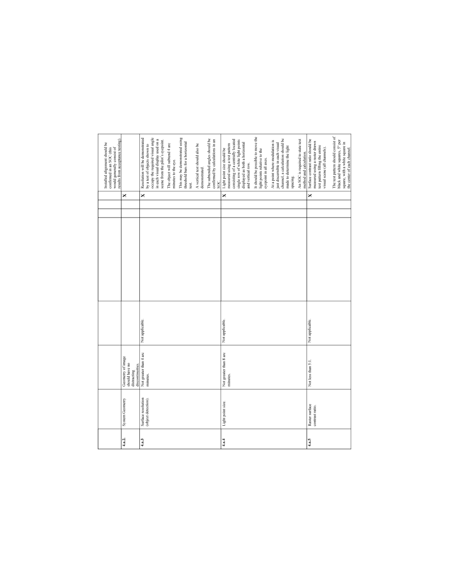
220
14 CFR Ch. I (1–1–24 Edition)
Pt. 60, App. B
VerDate Sep<11>2014
14:00 Mar 14, 2024
Jkt 262047
PO 00000
Frm 00230
Fmt 8010
Sfmt 8006
Q:\14\14V2.TXT
PC31
ER09DE22.090</GPH>
aworley on LAPBH6H6L3 with DISTILLER
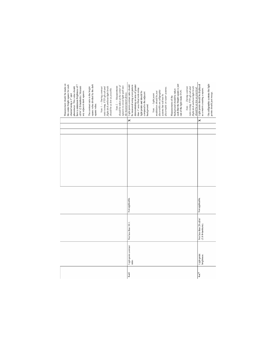
221
Federal Aviation Administration, DOT
Pt. 60, App. B
VerDate Sep<11>2014
14:00 Mar 14, 2024
Jkt 262047
PO 00000
Frm 00231
Fmt 8010
Sfmt 8006
Q:\14\14V2.TXT
PC31
ER09DE22.091</GPH>
aworley on LAPBH6H6L3 with DISTILLER
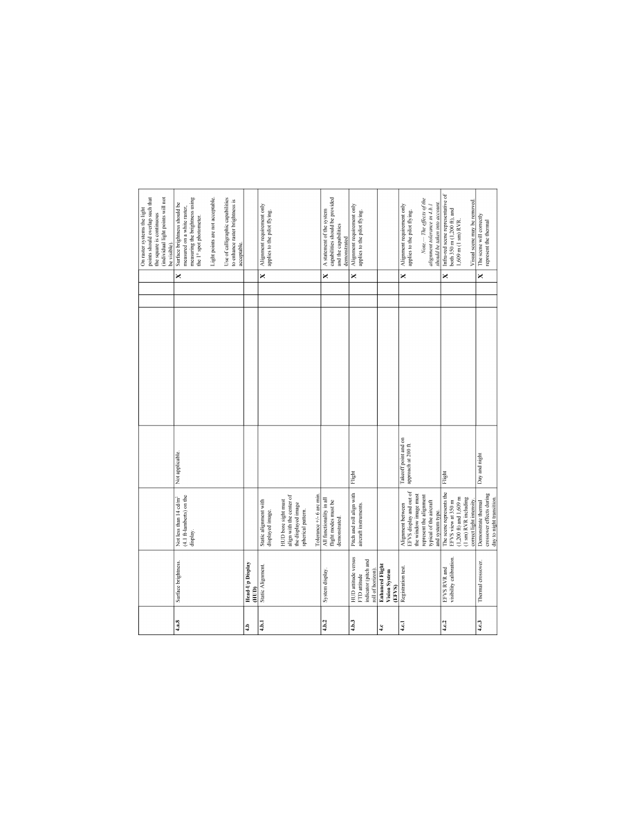
222
14 CFR Ch. I (1–1–24 Edition)
Pt. 60, App. B
VerDate Sep<11>2014
14:00 Mar 14, 2024
Jkt 262047
PO 00000
Frm 00232
Fmt 8010
Sfmt 8006
Q:\14\14V2.TXT
PC31
ER09DE22.092</GPH>
aworley on LAPBH6H6L3 with DISTILLER
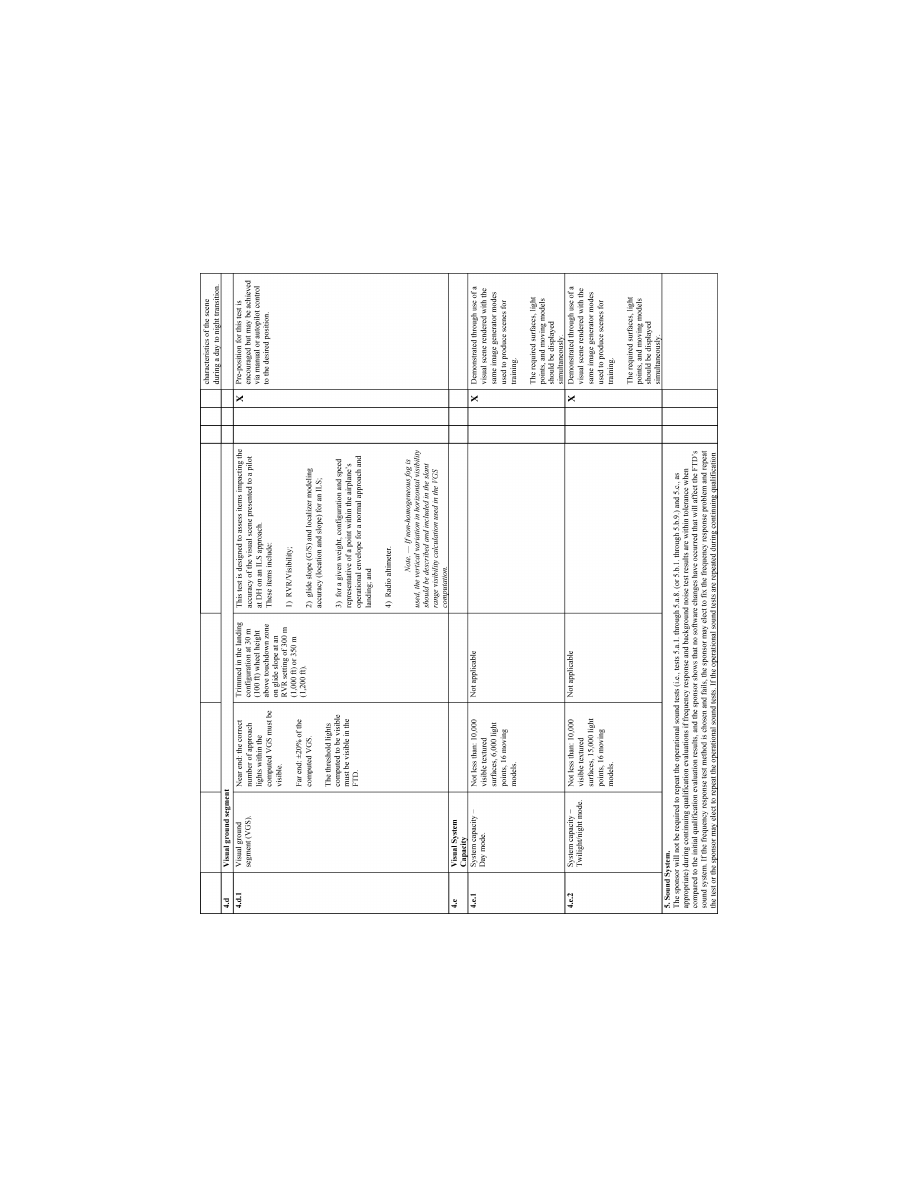
223
Federal Aviation Administration, DOT
Pt. 60, App. B
VerDate Sep<11>2014
14:00 Mar 14, 2024
Jkt 262047
PO 00000
Frm 00233
Fmt 8010
Sfmt 8006
Q:\14\14V2.TXT
PC31
ER09DE22.093</GPH>
aworley on LAPBH6H6L3 with DISTILLER
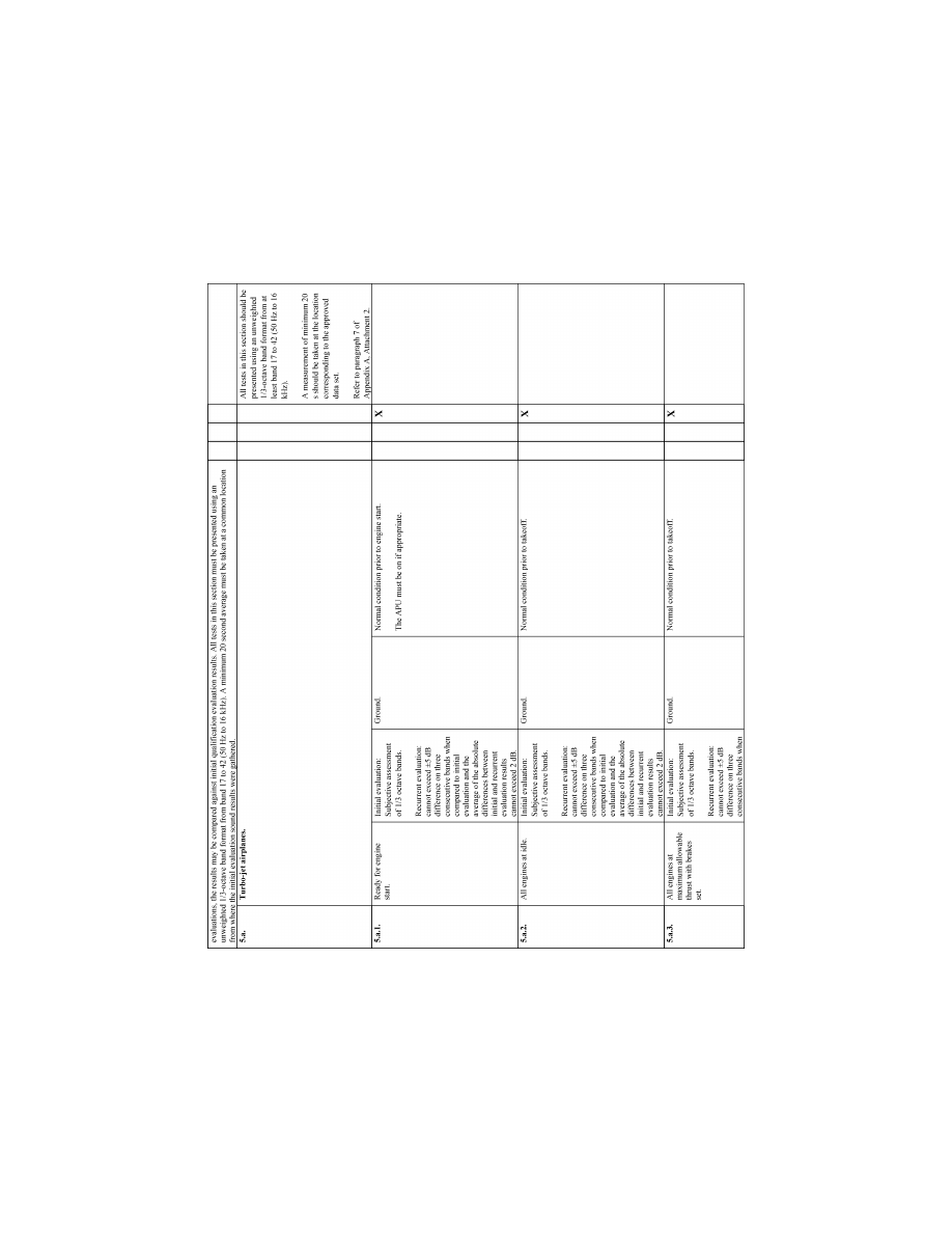
224
14 CFR Ch. I (1–1–24 Edition)
Pt. 60, App. B
VerDate Sep<11>2014
14:00 Mar 14, 2024
Jkt 262047
PO 00000
Frm 00234
Fmt 8010
Sfmt 8006
Q:\14\14V2.TXT
PC31
ER09DE22.094</GPH>
aworley on LAPBH6H6L3 with DISTILLER
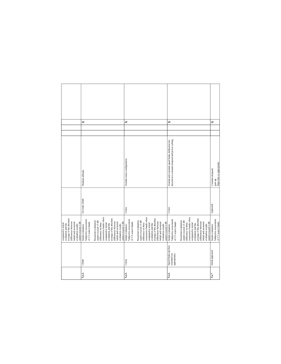
225
Federal Aviation Administration, DOT
Pt. 60, App. B
VerDate Sep<11>2014
14:00 Mar 14, 2024
Jkt 262047
PO 00000
Frm 00235
Fmt 8010
Sfmt 8006
Q:\14\14V2.TXT
PC31
ER09DE22.095</GPH>
aworley on LAPBH6H6L3 with DISTILLER
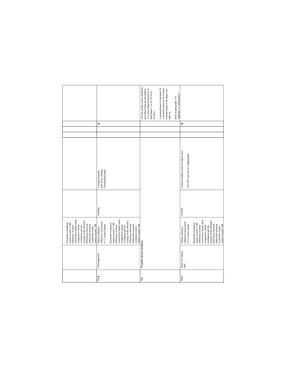
226
14 CFR Ch. I (1–1–24 Edition)
Pt. 60, App. B
VerDate Sep<11>2014
14:00 Mar 14, 2024
Jkt 262047
PO 00000
Frm 00236
Fmt 8010
Sfmt 8006
Q:\14\14V2.TXT
PC31
ER09DE22.096</GPH>
aworley on LAPBH6H6L3 with DISTILLER
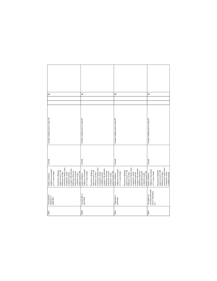
227
Federal Aviation Administration, DOT
Pt. 60, App. B
VerDate Sep<11>2014
14:00 Mar 14, 2024
Jkt 262047
PO 00000
Frm 00237
Fmt 8010
Sfmt 8006
Q:\14\14V2.TXT
PC31
ER09DE22.097</GPH>
aworley on LAPBH6H6L3 with DISTILLER
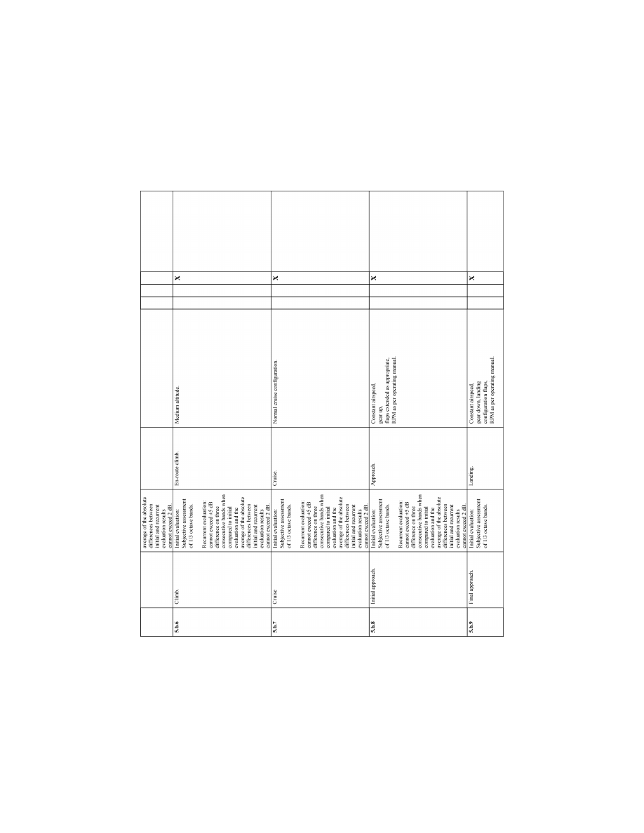
228
14 CFR Ch. I (1–1–24 Edition)
Pt. 60, App. B
VerDate Sep<11>2014
14:00 Mar 14, 2024
Jkt 262047
PO 00000
Frm 00238
Fmt 8010
Sfmt 8006
Q:\14\14V2.TXT
PC31
ER09DE22.098</GPH>
aworley on LAPBH6H6L3 with DISTILLER
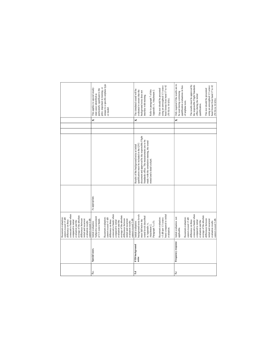
229
Federal Aviation Administration, DOT
Pt. 60, App. B
VerDate Sep<11>2014
14:00 Mar 14, 2024
Jkt 262047
PO 00000
Frm 00239
Fmt 8010
Sfmt 8006
Q:\14\14V2.TXT
PC31
ER09DE22.099</GPH>
aworley on LAPBH6H6L3 with DISTILLER
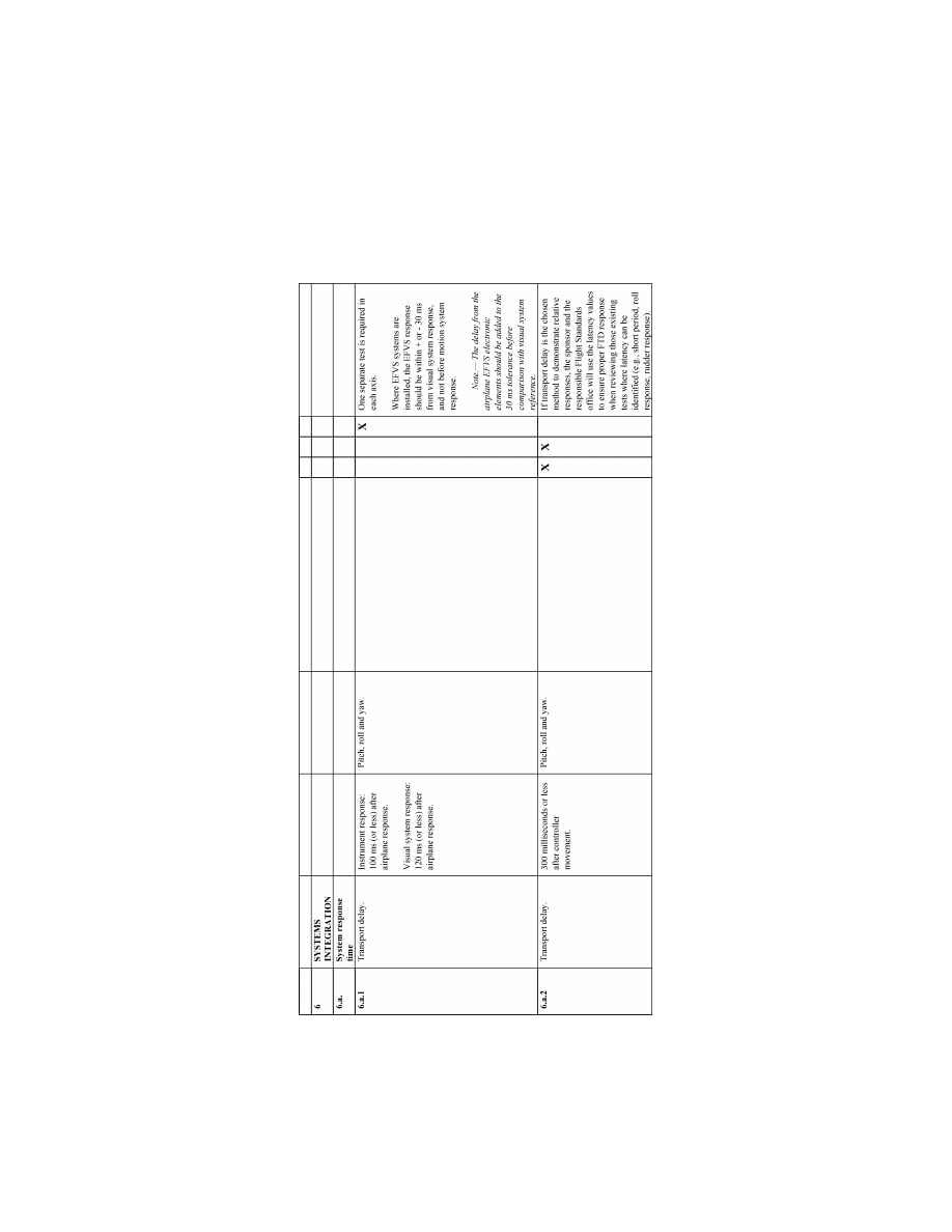
230
14 CFR Ch. I (1–1–24 Edition)
Pt. 60, App. B
VerDate Sep<11>2014
14:00 Mar 14, 2024
Jkt 262047
PO 00000
Frm 00240
Fmt 8010
Sfmt 8006
Q:\14\14V2.TXT
PC31
ER09DE22.100</GPH>
aworley on LAPBH6H6L3 with DISTILLER

231
Federal Aviation Administration, DOT
Pt. 60, App. B
llllllllllllllllllllllll
B
EGIN
I
NFORMATION
3. F
OR ADDITIONAL INFORMATION ON THE FOL
-
LOWING TOPICS
,
PLEASE REFER TO
A
PPENDIX
A, A
TTACHMENT
2,
AND THE INDICATED PARA
-
GRAPH WITHIN THAT ATTACHMENT
•
Control Dynamics, paragraph 4.
•
Motion System, paragraph 6.
•
Sound System, paragraph 7.
•
Engineering Simulator Validation Data,
paragraph 9.
•
Validation Test Tolerances, paragraph
11.
•
Validation Data Road Map, paragraph 12.
•
Acceptance Guidelines for Alternative
Engines Data, paragraph 13.
•
Acceptance Guidelines for Alternative
Avionics, paragraph 14.
•
Transport Delay Testing, paragraph 15.
•
Continuing Qualification Evaluation Val-
idation Data Presentation, paragraph 16.
E
ND
I
NFORMATION
llllllllllllllllllllllll
4. A
LTERNATIVE
O
BJECTIVE
D
ATA FOR
FTD
L
EVEL
5
llllllllllllllllllllllll
B
EGIN
QPS R
EQUIREMENTS
a. This paragraph (including the following
tables) is relevant only to FTD Level 5. It is
provided because this level is required to
simulate the performance and handling char-
acteristics of a set of airplanes with similar
characteristics, such as normal airspeed/alti-
tude operating envelope and the same num-
ber and type of propulsion systems (engines).
b. Tables B2B through B2E reflect FTD
performance standards that are acceptable
to the FAA. A sponsor must demonstrate
that a device performs within these param-
eters, as applicable. If a device does not meet
the established performance parameters for
some or for all of the applicable tests listed
in Tables B2B through B2E, the sponsor may
use FAA accepted flight test data for com-
parison purposes for those tests.
c. Sponsors using the data from Tables B2B
through B2E must comply with the fol-
lowing:
(1) Submit a complete QTG, including re-
sults from all of the objective tests appro-
priate for the level of qualification sought as
set out in Table B2A. The QTG must high-
light those results that demonstrate the per-
formance of the FTD is within the allowable
performance ranges indicated in Tables B2B
through B2E, as appropriate.
(2) The QTG test results must include all
relevant information concerning the condi-
tions under which the test was conducted;
e.g., gross weight, center of gravity, airspeed,
power setting, altitude (climbing, descend-
ing, or level), temperature, configuration,
and any other parameter that impacts the
conduct of the test.
(3) The test results become the validation
data against which the initial and all subse-
quent continuing qualification evaluations
are compared. These subsequent evaluations
will use the tolerances listed in Table B2A.
(4) Subjective testing of the device must be
performed to determine that the device per-
forms and handles like an airplane within
the appropriate set of airplanes.
E
ND
QPS R
EQUIREMENTS
llllllllllllllllllllllll
B
EGIN
I
NFORMATION
d. The reader is encouraged to consult the
Airplane Flight Simulator Evaluation Hand-
book, Volumes I and II, published by the
Royal Aeronautical Society, London, UK,
and AC 25–7, Flight Test Guide for Certifi-
cation of Transport Category Airplanes, and
AC 23–8A, Flight Test Guide for Certification
of Part 23 Airplanes, as amended, for ref-
erences and examples regarding flight test-
ing requirements and techniques.
E
ND
I
NFORMATION
llllllllllllllllllllllll
VerDate Sep<11>2014
14:00 Mar 14, 2024
Jkt 262047
PO 00000
Frm 00241
Fmt 8010
Sfmt 8002
Q:\14\14V2.TXT
PC31
aworley on LAPBH6H6L3 with DISTILLER
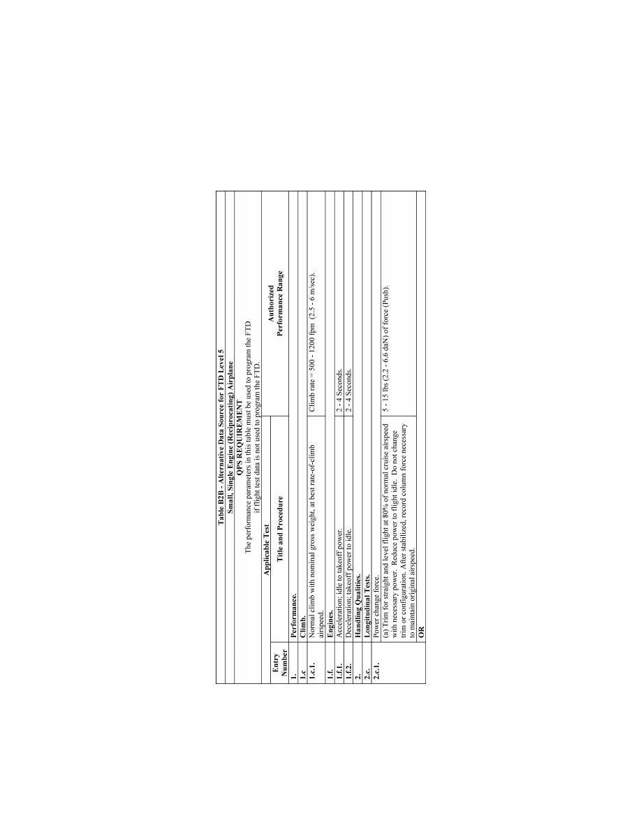
232
14 CFR Ch. I (1–1–24 Edition)
Pt. 60, App. B
VerDate Sep<11>2014
14:00 Mar 14, 2024
Jkt 262047
PO 00000
Frm 00242
Fmt 8010
Sfmt 8006
Q:\14\14V2.TXT
PC31
ER20MY16.171</GPH>
aworley on LAPBH6H6L3 with DISTILLER
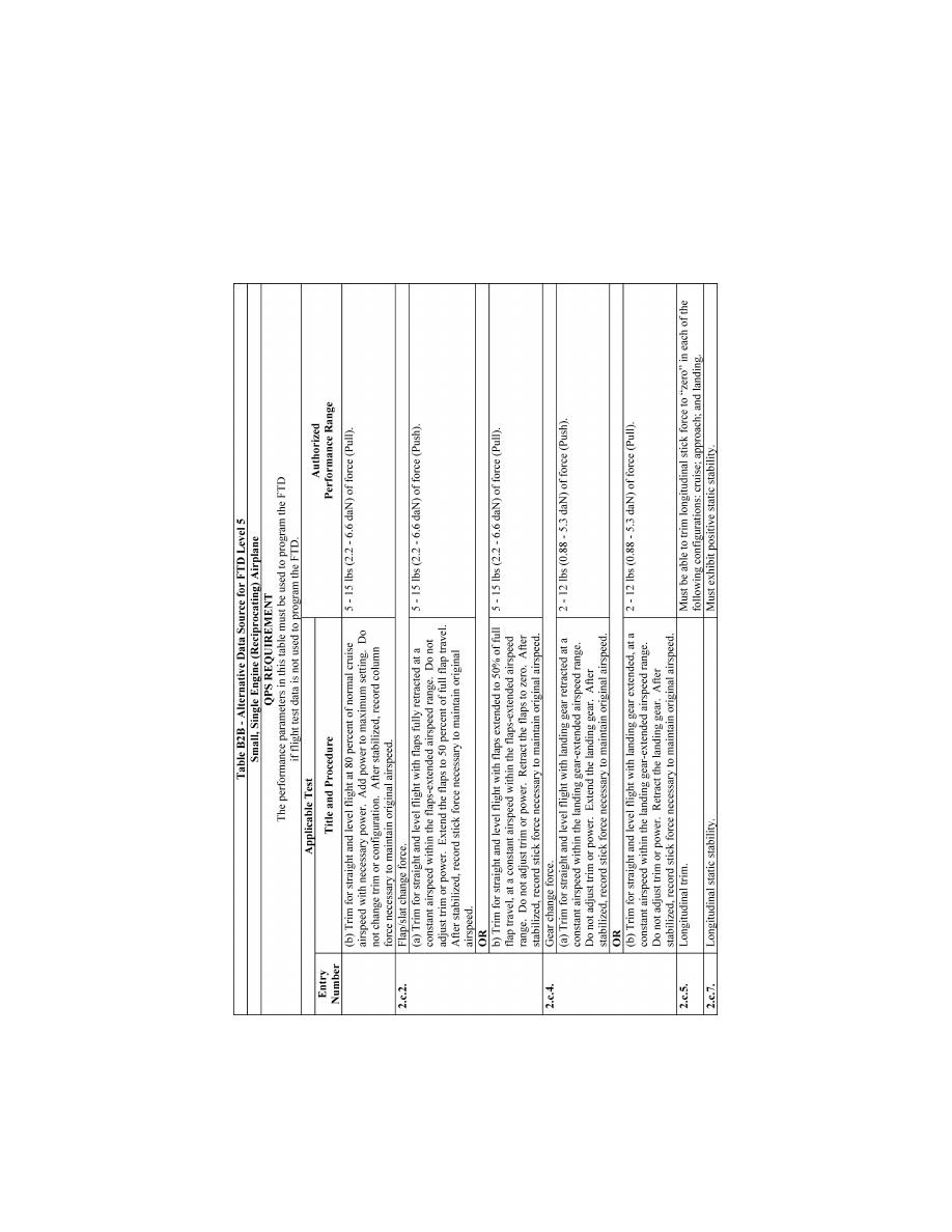
233
Federal Aviation Administration, DOT
Pt. 60, App. B
VerDate Sep<11>2014
14:00 Mar 14, 2024
Jkt 262047
PO 00000
Frm 00243
Fmt 8010
Sfmt 8006
Q:\14\14V2.TXT
PC31
ER20MY16.137</GPH>
aworley on LAPBH6H6L3 with DISTILLER
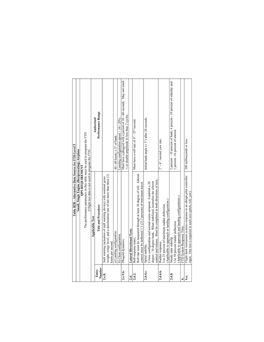
234
14 CFR Ch. I (1–1–24 Edition)
Pt. 60, App. B
VerDate Sep<11>2014
14:00 Mar 14, 2024
Jkt 262047
PO 00000
Frm 00244
Fmt 8010
Sfmt 8006
Q:\14\14V2.TXT
PC31
ER20MY16.138</GPH>
aworley on LAPBH6H6L3 with DISTILLER
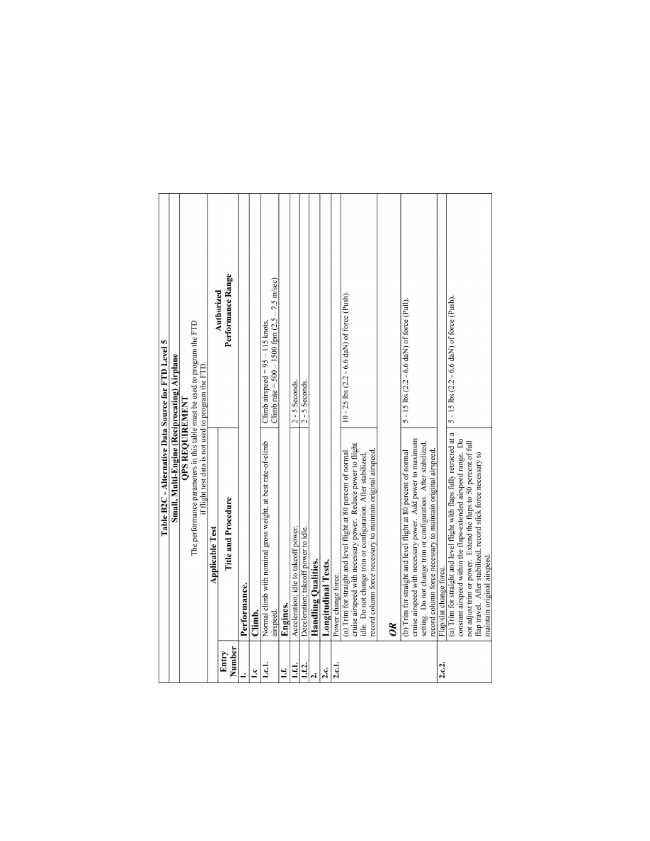
235
Federal Aviation Administration, DOT
Pt. 60, App. B
VerDate Sep<11>2014
14:00 Mar 14, 2024
Jkt 262047
PO 00000
Frm 00245
Fmt 8010
Sfmt 8006
Q:\14\14V2.TXT
PC31
ER20MY16.139</GPH>
aworley on LAPBH6H6L3 with DISTILLER
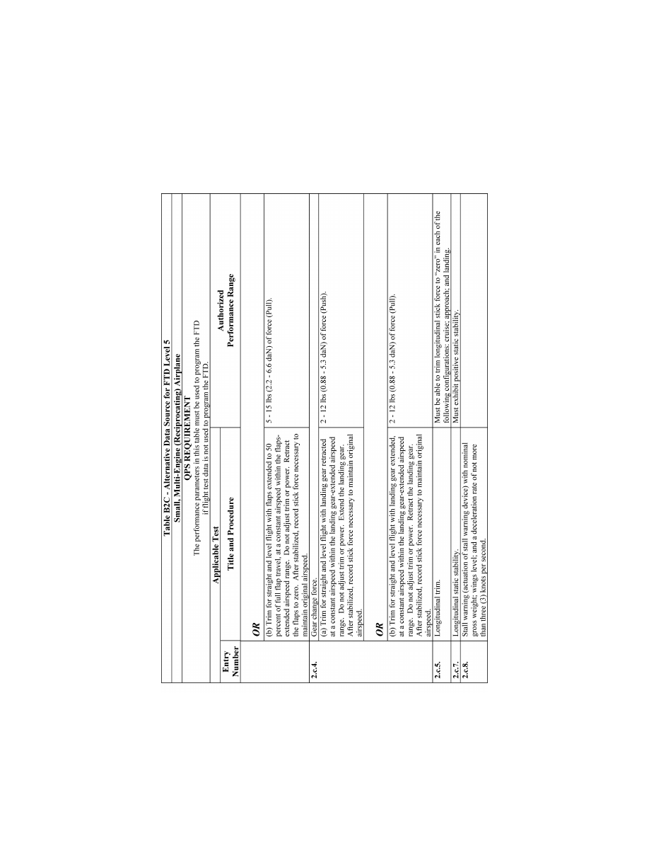
236
14 CFR Ch. I (1–1–24 Edition)
Pt. 60, App. B
VerDate Sep<11>2014
14:00 Mar 14, 2024
Jkt 262047
PO 00000
Frm 00246
Fmt 8010
Sfmt 8006
Q:\14\14V2.TXT
PC31
ER20MY16.140</GPH>
aworley on LAPBH6H6L3 with DISTILLER
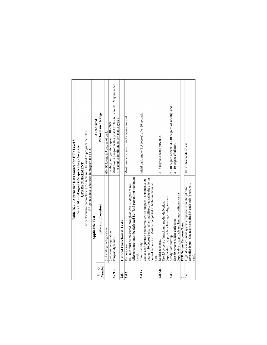
237
Federal Aviation Administration, DOT
Pt. 60, App. B
VerDate Sep<11>2014
14:00 Mar 14, 2024
Jkt 262047
PO 00000
Frm 00247
Fmt 8010
Sfmt 8006
Q:\14\14V2.TXT
PC31
ER20MY16.141</GPH>
aworley on LAPBH6H6L3 with DISTILLER

238
14 CFR Ch. I (1–1–24 Edition)
Pt. 60, App. B
VerDate Sep<11>2014
14:00 Mar 14, 2024
Jkt 262047
PO 00000
Frm 00248
Fmt 8010
Sfmt 8006
Q:\14\14V2.TXT
PC31
ER20MY16.142</GPH>
aworley on LAPBH6H6L3 with DISTILLER
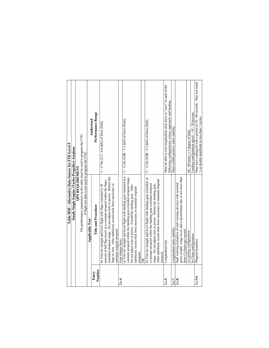
239
Federal Aviation Administration, DOT
Pt. 60, App. B
VerDate Sep<11>2014
14:00 Mar 14, 2024
Jkt 262047
PO 00000
Frm 00249
Fmt 8010
Sfmt 8006
Q:\14\14V2.TXT
PC31
ER20MY16.143</GPH>
aworley on LAPBH6H6L3 with DISTILLER
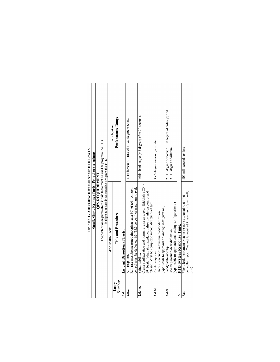
240
14 CFR Ch. I (1–1–24 Edition)
Pt. 60, App. B
VerDate Sep<11>2014
14:00 Mar 14, 2024
Jkt 262047
PO 00000
Frm 00250
Fmt 8010
Sfmt 8006
Q:\14\14V2.TXT
PC31
ER20MY16.144</GPH>
aworley on LAPBH6H6L3 with DISTILLER
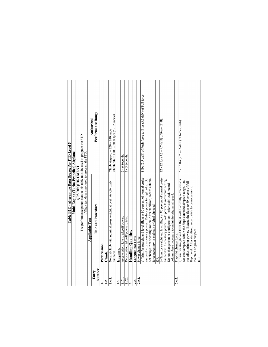
241
Federal Aviation Administration, DOT
Pt. 60, App. B
VerDate Sep<11>2014
14:00 Mar 14, 2024
Jkt 262047
PO 00000
Frm 00251
Fmt 8010
Sfmt 8006
Q:\14\14V2.TXT
PC31
ER20MY16.145</GPH>
aworley on LAPBH6H6L3 with DISTILLER
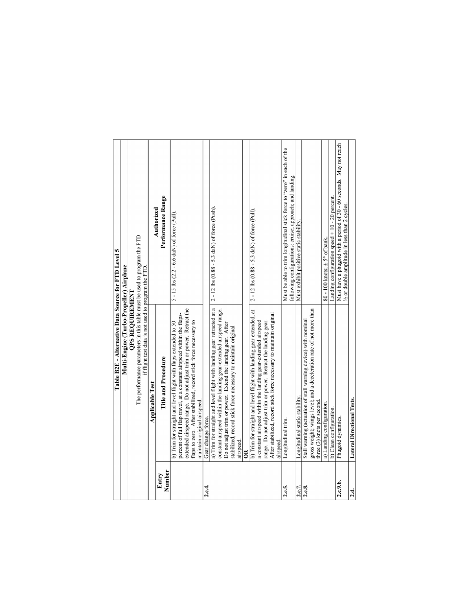
242
14 CFR Ch. I (1–1–24 Edition)
Pt. 60, App. B
VerDate Sep<11>2014
14:00 Mar 14, 2024
Jkt 262047
PO 00000
Frm 00252
Fmt 8010
Sfmt 8006
Q:\14\14V2.TXT
PC31
ER20MY16.146</GPH>
aworley on LAPBH6H6L3 with DISTILLER
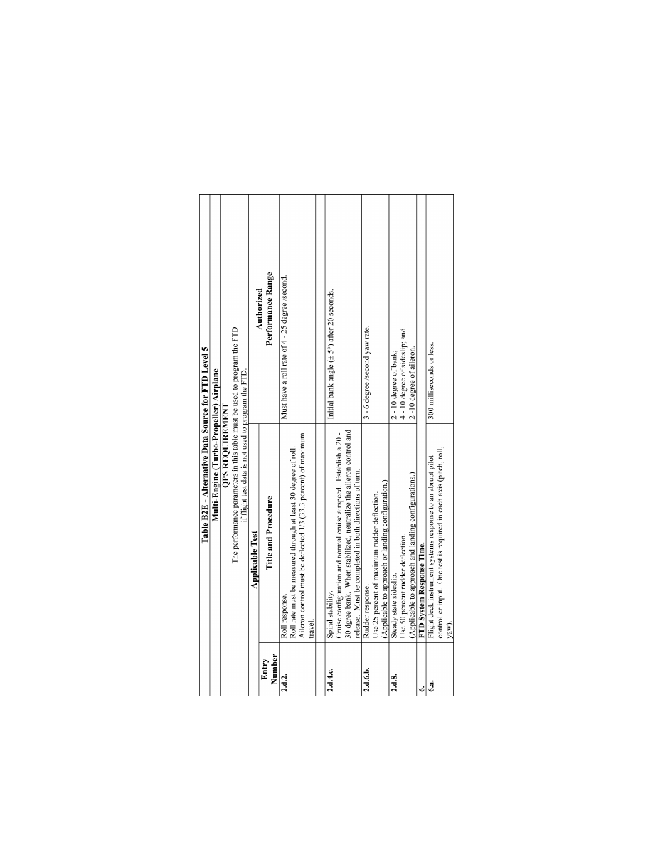
243
Federal Aviation Administration, DOT
Pt. 60, App. B
VerDate Sep<11>2014
14:00 Mar 14, 2024
Jkt 262047
PO 00000
Frm 00253
Fmt 8010
Sfmt 8006
Q:\14\14V2.TXT
PC31
ER20MY16.147</GPH>
aworley on LAPBH6H6L3 with DISTILLER

244
14 CFR Ch. I (1–1–24 Edition)
Pt. 60, App. B
E
ND
QPS R
EQUIREMENTS
llllllllllllllllllllllll
B
EGIN
QPS R
EQUIREMENTS
5. A
LTERNATIVE
D
ATA
S
OURCES
, P
ROCEDURES
,
AND
I
NSTRUMENTATION
: L
EVEL
6 FTD O
NLY
a. Sponsors are not required to use the al-
ternative data sources, procedures, and in-
strumentation. However, a sponsor may
choose to use one or more of the alternative
sources, procedures, and instrumentation de-
scribed in Table B2F.
E
ND
QPS R
EQUIREMENTS
llllllllllllllllllllllll
B
EGIN
I
NFORMATION
b. It has become standard practice for ex-
perienced FTD manufacturers to use such
techniques as a means of establishing data
bases for new FTD configurations while
awaiting the availability of actual flight test
data; and then comparing this new data with
the newly available flight test data. The re-
sults of such comparisons have, as reported
by some recognized and experienced simula-
tion experts, become increasingly consistent
and indicate that these techniques, applied
with appropriate experience, are becoming
dependably accurate for the development of
aerodynamic models for use in Level 6 FTDs.
c. In reviewing this history, the respon-
sible Flight Standards office has concluded
that, with proper care, those who are experi-
enced in the development of aerodynamic
models for FTD application can successfully
use these modeling techniques to acceptably
alter the method by which flight test data
may be acquired and, when applied to Level
6 FTDs, does not compromise the quality of
that simulation.
d. The information in the table that fol-
lows (Table of Alternative Data Sources,
Procedures, and Information: Level 6 FTD
Only) is presented to describe an acceptable
alternative to data sources for Level 6 FTD
modeling and validation, and an acceptable
alternative to the procedures and instrumen-
tation found in the flight test methods tradi-
tionally accepted for gathering modeling and
validation data.
(1) Alternative data sources that may be
used for part or all of a data requirement are
the Airplane Maintenance Manual, the Air-
plane Flight Manual (AFM), Airplane Design
Data, the Type Inspection Report (TIR), Cer-
tification Data or acceptable supplemental
flight test data.
(2) The responsible Flight Standards office
recommends that use of the alternative in-
strumentation noted in Table B2F be coordi-
nated with the responsible Flight Standards
office prior to employment in a flight test or
data gathering effort.
e. The responsible Flight Standards office
position regarding the use of these alter-
native data sources, procedures, and instru-
mentation is based on three primary pre-
conditions and presumptions regarding the
objective data and FTD aerodynamic pro-
gram modeling.
(1) Data gathered through the alternative
means does not require angle of attack
(AOA) measurements or control surface posi-
tion measurements for any flight test. AOA
can be sufficiently derived if the flight test
program insures the collection of acceptable
level, unaccelerated, trimmed flight data.
Angle of attack may be validated by con-
ducting the three basic ‘‘fly-by’’ trim tests.
The FTD time history tests should begin in
level, unaccelerated, and trimmed flight, and
the results should be compared with the
flight test pitch angle.
(2) A simulation controls system model
should be rigorously defined and fully ma-
ture. It should also include accurate gearing
and cable stretch characteristics (where ap-
plicable) that are determined from actual
aircraft measurements. Such a model does
not require control surface position measure-
ments in the flight test objective data for
Level 6 FTD applications.
f. Table B2F is not applicable to Computer
Controlled Aircraft FTDs.
g. Utilization of these alternate data
sources, procedures, and instrumentation
does not relieve the sponsor from compliance
with the balance of the information con-
tained in this document relative to Level 6
FTDs.
h. The term ‘‘inertial measurement sys-
tem’’ allows the use of a functional global
positioning system (GPS).
E
ND
I
NFORMATION
llllllllllllllllllllllll
VerDate Sep<11>2014
14:00 Mar 14, 2024
Jkt 262047
PO 00000
Frm 00254
Fmt 8010
Sfmt 8002
Q:\14\14V2.TXT
PC31
aworley on LAPBH6H6L3 with DISTILLER

245
Federal Aviation Administration, DOT
Pt. 60, App. B
T
ABLE
B2F—A
LTERNATIVE
D
ATA
S
OURCES
, P
ROCEDURES
,
AND
I
NSTRUMENTATION
L
EVEL
6 FTD
QPS Requirements
The standards in this table are required if the data gathering methods described in paragraph 9 of Appendix
B are not used.
Information
Objective test reference number
and title
Alternative data sources, procedures, and instrumentation
Notes
1.b.1. ................................................
Performance.
Takeoff.
Ground acceleration time.
Data may be acquired through a synchronized video recording of a
stop watch and the calibrated airplane airspeed indicator. Hand-
record the flight conditions and airplane configuration.
This test is re-
quired only if
RTO is
sought.
1.b.7. ................................................
Performance.
Takeoff.
Rejected takeoff.
Data may be acquired through a synchronized video recording of a
stop watch and the calibrated airplane airspeed indicator. Hand-
record the flight conditions and airplane configuration.
This test is re-
quired only if
RTO is
sought.
1.c.1. ................................................
Performance.
Climb.
Normal climb all engines operating.
Data may be acquired with a synchronized video of calibrated airplane
instruments and engine power throughout the climb range.
1.f.1. .................................................
Performance.
Engines.
Acceleration
Data may be acquired with a synchronized video recording of engine
instruments and throttle position.
1.f.2. .................................................
Performance.
Engines.
Deceleration
Data may be acquired with a synchronized video recording of engine
instruments and throttle position.
2.a.1.a. Handling qualities. Static
control tests. Pitch controller posi-
tion vs. force and surface position
calibration.
Surface position data may be acquired from flight data recorder (FDR)
sensor or, if no FDR sensor, at selected, significant column positions
(encompassing significant column position data points), acceptable
to the responsible Flight Standards office, using a control surface
protractor on the ground. Force data may be acquired by using a
hand held force gauge at the same column position data points..
For airplanes
with reversible
control sys-
tems, surface
position data
acquisition
should be ac-
complished
with winds
less than 5
kts.
2.a.2.a. Handling qualities. Static
control tests. Wheel position vs.
force and surface position calibra-
tion..
Surface position data may be acquired from flight data recorder (FDR)
sensor or, if no FDR sensor, at selected, significant wheel positions
(encompassing significant wheel position data points), acceptable to
the responsible Flight Standards office, using a control surface pro-
tractor on the ground. Force data may be acquired by using a hand
held force gauge at the same wheel position data points..
For airplanes
with reversible
control sys-
tems, surface
position data
acquisition
should be ac-
complished
with winds
less than 5
kts.
2.a.3.a. Handling qualities. Static
control tests. Rudder pedal posi-
tion vs. force and surface position
calibration..
Surface position data may be acquired from flight data recorder (FDR)
sensor or, if no FDR sensor, at selected, significant rudder pedal po-
sitions (encompassing significant rudder pedal position data points),
acceptable to the responsible Flight Standards office, using a control
surface protractor on the ground. Force data may be acquired by
using a hand held force gauge at the same rudder pedal position
data points..
For airplanes
with reversible
control sys-
tems, surface
position data
acquisition
should be ac-
complished
with winds
less than 5
kts.
2.a.4. ................................................
Handling qualities.
Static control tests.
Nosewheel steering force.
Breakout data may be acquired with a hand held force gauge. The re-
mainder of the force to the stops may be calculated if the force
gauge and a protractor are used to measure force after breakout for
at least 25% of the total displacement capability.
2.a.5. ................................................
Handling qualities.
Static control tests.
Rudder pedal steering calibration.
Data may be acquired through the use of force pads on the rudder
pedals and a pedal position measurement device, together with de-
sign data for nosewheel position.
VerDate Sep<11>2014
14:00 Mar 14, 2024
Jkt 262047
PO 00000
Frm 00255
Fmt 8010
Sfmt 8002
Q:\14\14V2.TXT
PC31
aworley on LAPBH6H6L3 with DISTILLER

246
14 CFR Ch. I (1–1–24 Edition)
Pt. 60, App. B
T
ABLE
B2F—A
LTERNATIVE
D
ATA
S
OURCES
, P
ROCEDURES
,
AND
I
NSTRUMENTATION
L
EVEL
6 FTD—
Continued
QPS Requirements
The standards in this table are required if the data gathering methods described in paragraph 9 of Appendix
B are not used.
Information
Objective test reference number
and title
Alternative data sources, procedures, and instrumentation
Notes
2.a.6. ................................................
Handling qualities.
Static control tests.
Pitch trim indicator vs. surface posi-
tion calibration.
Data may be acquired through calculations.
2.a.8. ................................................
Handling qualities.
Static control tests.
Alignment of power lever angle vs.
selected engine parameter (e.g.,
EPR, N
1
, Torque, Manifold pres-
sure).
Data may be acquired through the use of a temporary throttle quadrant
scale to document throttle position. Use a synchronized video to
record steady state instrument readings or hand-record steady state
engine performance readings.
2.a.9. ................................................
Handling qualities.
Static control tests.
Brake pedal position vs. force.
Use of design or predicted data is acceptable. Data may be acquired
by measuring deflection at ‘‘zero’’ and at ‘‘maximum.’’
2.c.1. ................................................
Handling qualities.
Longitudinal control tests.
Power change force.
Data may be acquired by using an inertial measurement system and a
synchronized video of the calibrated airplane instruments, throttle po-
sition, and the force/position measurements of flight deck controls.
Power change
dynamics test
is acceptable
using the
same data ac-
quisition
methodology.
2.c.2. ................................................
Handling qualities.
Longitudinal control tests.
Flap/slat change force.
Data may be acquired by using an inertial measurement system and a
synchronized video of calibrated airplane instruments, flap/slat posi-
tion, and the force/position measurements of flight deck controls.
Flap/slat change
dynamics test
is acceptable
using the
same data ac-
quisition
methodology.
2.c.4. ................................................
Handling qualities.
Longitudinal control tests.
Gear change force.
Data may be acquired by using an inertial measurement system and a
synchronized video of the calibrated airplane instruments, gear posi-
tion, and the force/position measurements of flight deck controls.
Gear change dy-
namics test is
acceptable
using the
same data ac-
quisition
methodology.
2.c.5. ................................................
Handling qualities.
Longitudinal control tests.
Longitudinal trim.
Data may be acquired through use of an inertial measurement system
and a synchronized video of flight deck controls position (previously
calibrated to show related surface position) and engine instrument
readings.
2.c.6. ................................................
Handling qualities.
Longitudinal control tests.
Longitudinal maneuvering stability
(stick force/g).
Data may be acquired through the use of an inertial measurement sys-
tem and a synchronized video of the calibrated airplane instruments;
a temporary, high resolution bank angle scale affixed to the attitude
indicator; and a wheel and column force measurement indication.
2.c.7. ................................................
Handling qualities.
Longitudinal control tests.
Longitudinal static stability
Data may be acquired through the use of a synchronized video of the
airplane flight instruments and a hand held force gauge.
2.c.8. ................................................
Handling qualities.
Longitudinal control tests.
Stall Warning (activation of stall
warning device).
Data may be acquired through a synchronized video recording of a
stop watch and the calibrated airplane airspeed indicator. Hand-
record the flight conditions and airplane configuration.
Airspeeds may
be cross
checked with
those in the
TIR and AFM.
VerDate Sep<11>2014
14:00 Mar 14, 2024
Jkt 262047
PO 00000
Frm 00256
Fmt 8010
Sfmt 8002
Q:\14\14V2.TXT
PC31
aworley on LAPBH6H6L3 with DISTILLER

247
Federal Aviation Administration, DOT
Pt. 60, App. B
T
ABLE
B2F—A
LTERNATIVE
D
ATA
S
OURCES
, P
ROCEDURES
,
AND
I
NSTRUMENTATION
L
EVEL
6 FTD—
Continued
QPS Requirements
The standards in this table are required if the data gathering methods described in paragraph 9 of Appendix
B are not used.
Information
Objective test reference number
and title
Alternative data sources, procedures, and instrumentation
Notes
2.c.9.a. .............................................
Handling qualities.
Longitudinal control tests.
Phugoid dynamics.
Data may be acquired by using an inertial measurement system and a
synchronized video of the calibrated airplane instruments and the
force/position measurements of flight deck controls.
2.c.10. ..............................................
Handling qualities.
Longitudinal control tests.
Short period dynamics.
Data may be acquired by using an inertial measurement system and a
synchronized video of the calibrated airplane instruments and the
force/position measurements of flight deck controls.
2.c.11. ..............................................
Handling qualities.
Longitudinal control tests.
Gear and flap/slat operating times.
May use design data, production flight test schedule, or maintenance
specification, together with an SOC.
2.d.2. ................................................
Handling qualities.
Lateral directional tests.
Roll response (rate).
Data may be acquired by using an inertial measurement system and a
synchronized video of the calibrated airplane instruments and the
force/position measurements of flight deck lateral controls.
2.d.3. ................................................
Handling qualities.
Lateral directional tests.
(a) Roll overshoot.
OR
(b) Roll response to flight deck roll
controller step input.
Data may be acquired by using an inertial measurement system and a
synchronized video of the calibrated airplane instruments and the
force/position measurements of flight deck lateral controls.
2.d.4. ................................................
Handling qualities.
Lateral directional tests.
Spiral stability.
Data may be acquired by using an inertial measurement system and a
synchronized video of the calibrated airplane instruments; the force/
position measurements of flight deck controls; and a stop watch.
2.d.6.a. .............................................
Handling qualities.
Lateral directional tests.
Rudder response.
Data may be acquired by using an inertial measurement system and a
synchronized video of the calibrated airplane instruments; the force/
position measurements of rudder pedals.
2.d.7. ................................................
Handling qualities.
Lateral directional tests.
Dutch roll, (yaw damper OFF).
Data may be acquired by using an inertial measurement system and a
synchronized video of the calibrated airplane instruments and the
force/position measurements of flight deck controls.
2.d.8. ................................................
Handling qualities.
Lateral directional tests.
Steady state sideslip.
Data may be acquired by using an inertial measurement system and a
synchronized video of the calibrated airplane instruments and the
force/position measurements of flight deck controls.
A
TTACHMENT
3
TO
A
PPENDIX
B
TO
P
ART
60—
F
LIGHT
T
RAINING
D
EVICE
(FTD) S
UBJECTIVE
E
VALUATION
llllllllllllllllllllllll
B
EGIN
I
NFORMATION
1. D
ISCUSSION
a. The subjective tests provide a basis for
evaluating the capability of the FTD to per-
form over a typical utilization period. The
items listed in the Table of Functions and
Subjective Tests are used to determine
whether the FTD competently simulates
each required maneuver, procedure, or task;
and verifying correct operation of the FTD
controls, instruments, and systems. The
tasks do not limit or exceed the authoriza-
tions for use of a given level of FTD as de-
scribed on the SOQ or as approved by the
TPAA. All items in the following paragraphs
are subject to examination.
b. All simulated airplane systems func-
tions will be assessed for normal and, where
appropriate, alternate operations. Simulated
airplane systems are listed separately under
‘‘Any Flight Phase’’ to ensure appropriate
attention to systems checks. Operational
VerDate Sep<11>2014
14:00 Mar 14, 2024
Jkt 262047
PO 00000
Frm 00257
Fmt 8010
Sfmt 8002
Q:\14\14V2.TXT
PC31
aworley on LAPBH6H6L3 with DISTILLER

248
14 CFR Ch. I (1–1–24 Edition)
Pt. 60, App. B
navigation systems (including inertial navi-
gation systems, global positioning systems,
or other long-range systems) and the associ-
ated electronic display systems will be eval-
uated if installed. The pilot will include in
his report to the TPAA, the effect of the sys-
tem operation and any system limitation.
c. At the request of the TPAA, the Pilot
may assess the FTD for a special aspect of a
sponsor’s training program during the func-
tions and subjective portion of an evalua-
tion. Such an assessment may include a por-
tion of a specific operation (e.g., a Line Ori-
ented Flight Training (LOFT) scenario) or
special emphasis items in the sponsor’s
training program. Unless directly related to
a requirement for the qualification level, the
results of such an evaluation would not af-
fect the qualification of the FTD.
E
ND
I
NFORMATION
llllllllllllllllllllllll
T
ABLE
B3A—T
ABLE OF
F
UNCTIONS AND
S
UBJECTIVE
T
ESTS
L
EVEL
6 FTD
QPS requirements
Entry No.
Operations tasks
Tasks in this table are subject to evaluation if appropriate for the airplane system or systems simulated as indicated in the SOQ
Configuration List as defined in Appendix B, Attachment 2 of this part.
1. Preflight
Accomplish a functions check of all installed switches, indicators, systems, and equipment at all crewmembers’
and instructors’ stations, and determine that the flight deck (or flight deck area) design and functions replicate
the appropriate airplane.
2. Surface Operations (pre-takeoff)
2.a. ............
Engine start:
2.a.1. .........
Normal start.
2.a.2. .........
Alternative procedures start.
2.a.3. .........
Abnormal procedures start/shut down.
2.b. ............
Pushback/Powerback (powerback requires visual system).
3. Takeoff (requires appropriate visual system as set out in Table B1A, item 6; Appendix B, Attachment 1.)
3.a. ............
Instrument takeoff:
3.a.1. .........
Engine checks (e.g., engine parameter relationships, propeller/mixture controls).
3.a.2. .........
Acceleration characteristics.
3.a.3. .........
Nosewheel/rudder steering.
3.a.4. .........
Landing gear, wing flap, leading edge device operation.
3.b. ............
Rejected takeoff:
3.b.1. .........
Deceleration characteristics.
3.b.2. .........
Brakes/engine reverser/ground spoiler operation.
3.b.3. .........
Nosewheel/rudder steering.
4. In-Flight Operations
4.a. ............
Normal climb.
4.b. ............
Cruise:
4.b.1. .........
Demonstration of performance characteristics (speed vs. power).
4.b.2. .........
Normal turns.
4.b.3. .........
Demonstration of high altitude handling.
4.b.4. .........
Demonstration of high airspeed handling/overspeed warning.
4.b.5. .........
Demonstration of Mach effects on control and trim.
VerDate Sep<11>2014
14:00 Mar 14, 2024
Jkt 262047
PO 00000
Frm 00258
Fmt 8010
Sfmt 8002
Q:\14\14V2.TXT
PC31
aworley on LAPBH6H6L3 with DISTILLER

249
Federal Aviation Administration, DOT
Pt. 60, App. B
T
ABLE
B3A—T
ABLE OF
F
UNCTIONS AND
S
UBJECTIVE
T
ESTS
L
EVEL
6 FTD—Continued
QPS requirements
Entry No.
Operations tasks
4.b.6. .........
Steep turns.
4.b.7. .........
In-Flight engine shutdown (procedures only).
4.b.8. .........
In-Flight engine restart (procedures only).
4.b.9. .........
Specific flight characteristics.
4.b.10. .......
Response to loss of flight control power.
4.b.11. .......
Response to other flight control system failure modes.
4.b.12. .......
Operations during icing conditions.
4.b.13. .......
Effects of airframe/engine icing.
4.c. ............
Other flight phase:
4.c.1. .........
Approach to stalls in the following configurations:
4.c.1.a. ......
Cruise.
4.c.1.b. ......
Takeoff or approach.
4.c.1.c. ......
Landing.
4.c.2. .........
High angle of attack maneuvers in the following configurations:
4.c.2.a. ......
Cruise.
4.c.2.b. ......
Takeoff or approach.
4.c.2.c. ......
Landing.
4.c.3. .........
Slow flight.
4.c.4. .........
Holding.
5. Approaches
5.a.
Non-precision Instrument Approaches:
5.a.1. .........
With use of autopilot and autothrottle, as applicable.
5.a.2. .........
Without use of autopilot and autothrottle, as applicable.
5.a.3. .........
With 10 knot tail wind.
5.a.4. .........
With 10 knot crosswind.
5.b. ............
Precision Instrument Approaches:
5.b.1. .........
With use of autopilot, autothrottle, and autoland, as applicable.
5.b.2. .........
Without use of autopilot, autothrottle, and autoland, as applicable.
5.b.3. .........
With 10 knot tail wind.
5.b.4. .........
With 10 knot crosswind.
6. Missed Approach
6.a. ............
Manually controlled.
6.b. ............
Automatically controlled (if applicable).
7. Any Flight Phase, as appropriate
7.a. ............
Normal system operation (installed systems).
7.b. ............
Abnormal/Emergency system operation (installed systems).
VerDate Sep<11>2014
14:00 Mar 14, 2024
Jkt 262047
PO 00000
Frm 00259
Fmt 8010
Sfmt 8002
Q:\14\14V2.TXT
PC31
aworley on LAPBH6H6L3 with DISTILLER

250
14 CFR Ch. I (1–1–24 Edition)
Pt. 60, App. B
T
ABLE
B3A—T
ABLE OF
F
UNCTIONS AND
S
UBJECTIVE
T
ESTS
L
EVEL
6 FTD—Continued
QPS requirements
Entry No.
Operations tasks
7.c. ............
Flap operation.
7.d. ............
Landing gear operation.
7.e. ............
Engine Shutdown and Parking.
7.e.1. .........
Systems operation.
7.e.2. .........
Parking brake operation.
8. Instructor Operating Station (IOS), as appropriate. Functions in this section are subject to evaluation only if appropriate
for the airplane and/or installed on the specific FTD involved
8.a. ............
Power Switch(es).
8.b. ............
Airplane conditions.
8.b.1. .........
Gross weight, center of gravity, and fuel loading and allocation.
8.b.2. .........
Airplane systems status.
8.b.3. .........
Ground crew functions (e.g., external power, push back).
8.c. ............
Airports.
8.c.1. .........
Selection.
8.c.2. .........
Runway selection.
8.c.3. .........
Preset positions (e.g., ramp, over FAF).
8.d. ............
Environmental controls.
8.d.1. .........
Temperature.
8.d.2. .........
Climate conditions (e.g., ice, rain).
8.d.3. .........
Wind speed and direction.
8.e. ............
Airplane system malfunctions.
8.e.1. .........
Insertion/deletion.
8.e.2. .........
Problem clear.
8.f. .............
Locks, Freezes, and Repositioning.
8.f.1. ..........
Problem (all) freeze/release.
8.f.2. ..........
Position (geographic) freeze/release.
8.f.3. ..........
Repositioning (locations, freezes, and releases).
8.f.4. ..........
Ground speed control.
8.f.5. ..........
Remote IOS, if installed.
9. Sound Controls. On/off/adjustment
10. Control Loading System (as applicable) On/off/emergency stop.
11. Observer Stations.
11.a. ..........
Position.
11.b. ..........
Adjustments.
End QPS Requirements
VerDate Sep<11>2014
14:00 Mar 14, 2024
Jkt 262047
PO 00000
Frm 00260
Fmt 8010
Sfmt 8002
Q:\14\14V2.TXT
PC31
aworley on LAPBH6H6L3 with DISTILLER

251
Federal Aviation Administration, DOT
Pt. 60, App. B
T
ABLE
B3B—T
ABLE OF
F
UNCTIONS AND
S
UBJECTIVE
T
ESTS
L
EVEL
5 FTD
QPS requirements
Entry No.
Operations tasks
Tasks in this table are subject to evaluation if appropriate for the airplane system or systems simulated as indi-
cated in the SOQ Configuration List as defined in Appendix B, Attachment 2 of this part.
1. Preflight
Accomplish a functions check of all installed switches, indicators, systems, and equipment at all crewmembers’
and instructors’ stations, and determine that the flight deck (or flight deck area) design and functions replicate
the appropriate airplane.
2. Surface Operations (pre-takeoff)
2.a. ............
Engine start (if installed):
2.a.1. .........
Normal start.
2.a.2. .........
Alternative procedures start.
2.a.3. .........
Abnormal/Emergency procedures start/shut down.
3. In-Flight Operations
3.a. ............
Normal climb.
3.b. ............
Cruise:
3.b.1. .........
Performance characteristics (speed vs. power).
3.b.2. .........
Normal turns.
3.c. ............
Normal descent.
4. Approaches
4.a. ............
Coupled instrument approach maneuvers (as applicable for the systems installed).
5. Any Flight Phase
5.a. ............
Normal system operation (Installed systems).
5.b. ............
Abnormal/Emergency system operation (Installed systems).
5.c. ............
Flap operation.
5.d. ............
Landing gear operation
5.e. ............
Engine Shutdown and Parking (if installed).
5.e.1. .........
Systems operation.
5.e.2. .........
Parking brake operation.
6. Instructor Operating Station (IOS)
6.a. ............
Power Switch(es).
6.b. ............
Preset positions—ground, air.
6.c. ............
Airplane system malfunctions (Installed systems).
6.c.1. .........
Insertion/deletion.
6.c.2. .........
Problem clear.
VerDate Sep<11>2014
14:00 Mar 14, 2024
Jkt 262047
PO 00000
Frm 00261
Fmt 8010
Sfmt 8006
Q:\14\14V2.TXT
PC31
aworley on LAPBH6H6L3 with DISTILLER
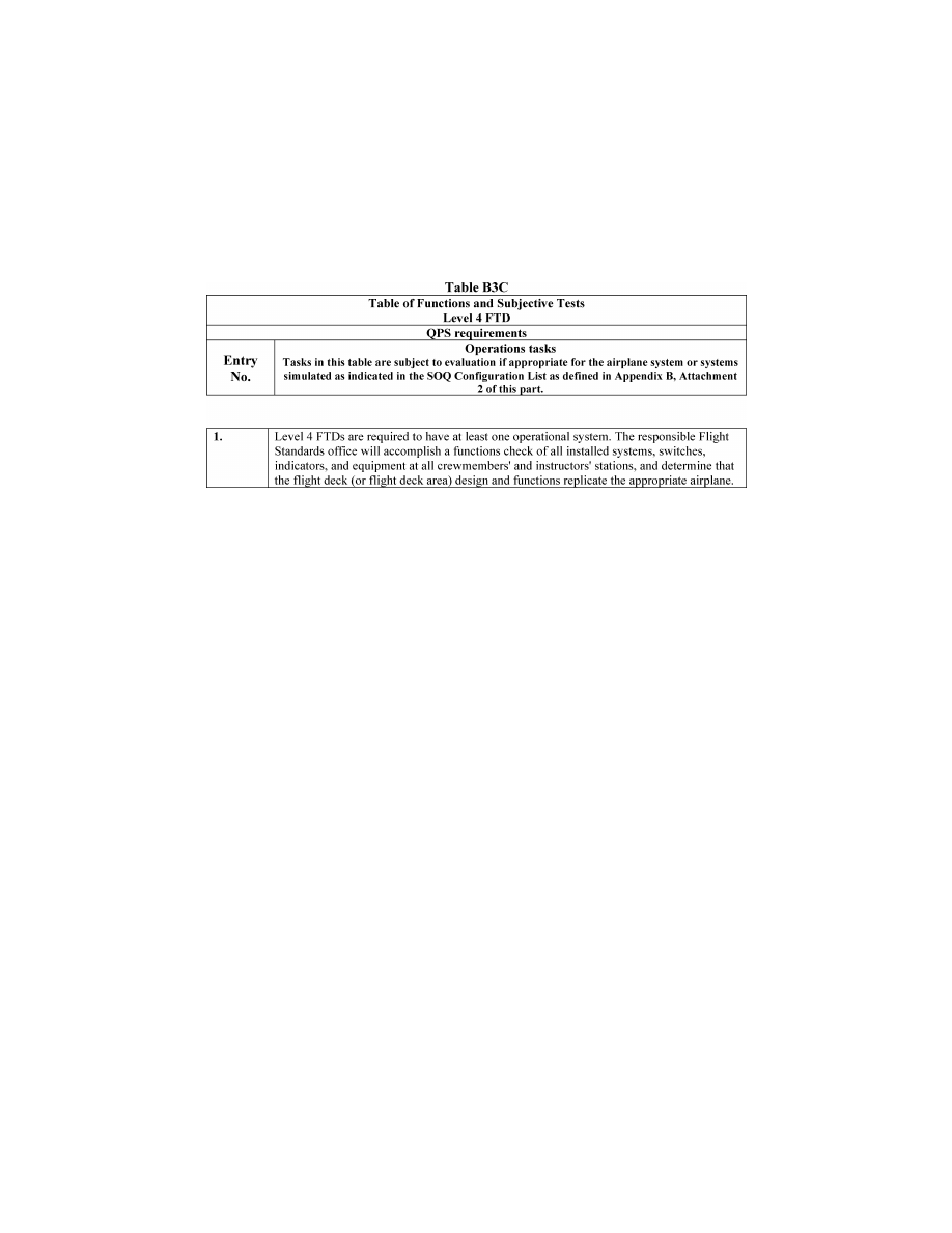
252
14 CFR Ch. I (1–1–24 Edition)
Pt. 60, App. B
VerDate Sep<11>2014
14:00 Mar 14, 2024
Jkt 262047
PO 00000
Frm 00262
Fmt 8010
Sfmt 8006
Q:\14\14V2.TXT
PC31
ER09DE22.102</GPH>
aworley on LAPBH6H6L3 with DISTILLER
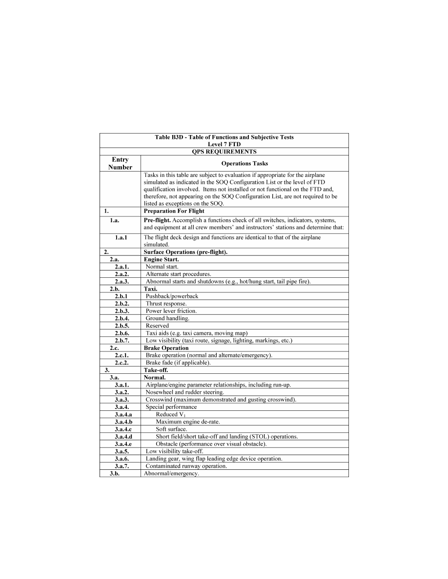
253
Federal Aviation Administration, DOT
Pt. 60, App. B
VerDate Sep<11>2014
14:00 Mar 14, 2024
Jkt 262047
PO 00000
Frm 00263
Fmt 8010
Sfmt 8006
Q:\14\14V2.TXT
PC31
ER20MY16.148</GPH>
aworley on LAPBH6H6L3 with DISTILLER
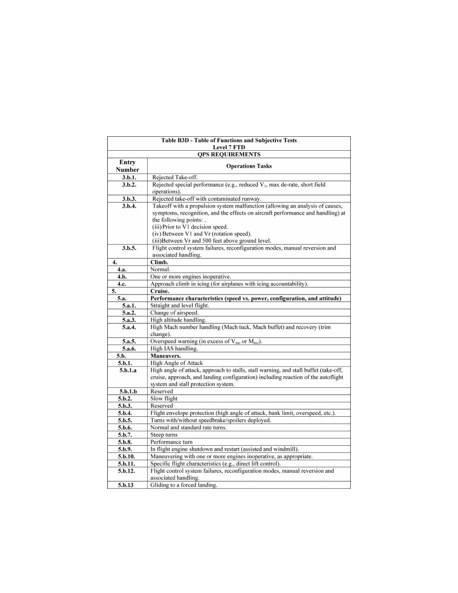
254
14 CFR Ch. I (1–1–24 Edition)
Pt. 60, App. B
VerDate Sep<11>2014
14:00 Mar 14, 2024
Jkt 262047
PO 00000
Frm 00264
Fmt 8010
Sfmt 8006
Q:\14\14V2.TXT
PC31
ER20MY16.149</GPH>
aworley on LAPBH6H6L3 with DISTILLER
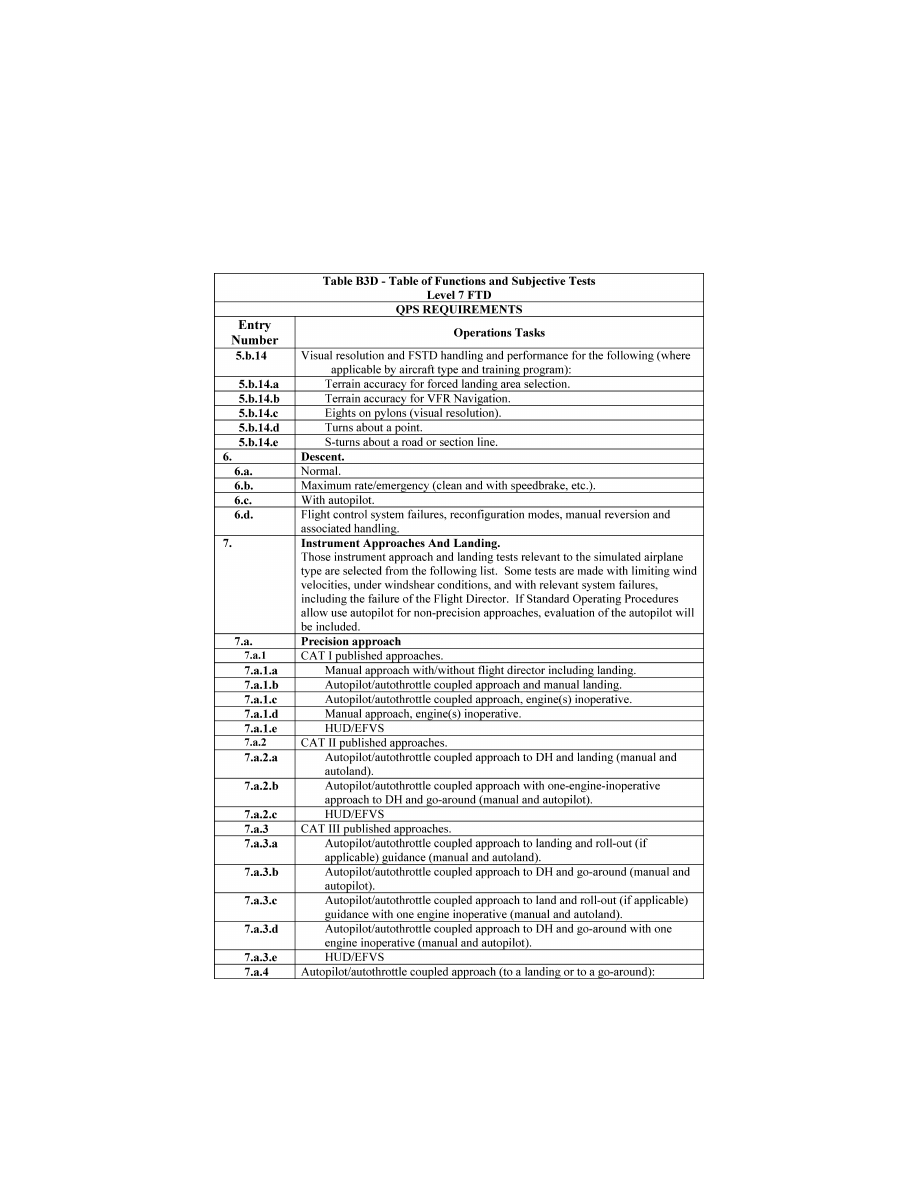
255
Federal Aviation Administration, DOT
Pt. 60, App. B
VerDate Sep<11>2014
14:00 Mar 14, 2024
Jkt 262047
PO 00000
Frm 00265
Fmt 8010
Sfmt 8006
Q:\14\14V2.TXT
PC31
ER20MY16.150</GPH>
aworley on LAPBH6H6L3 with DISTILLER
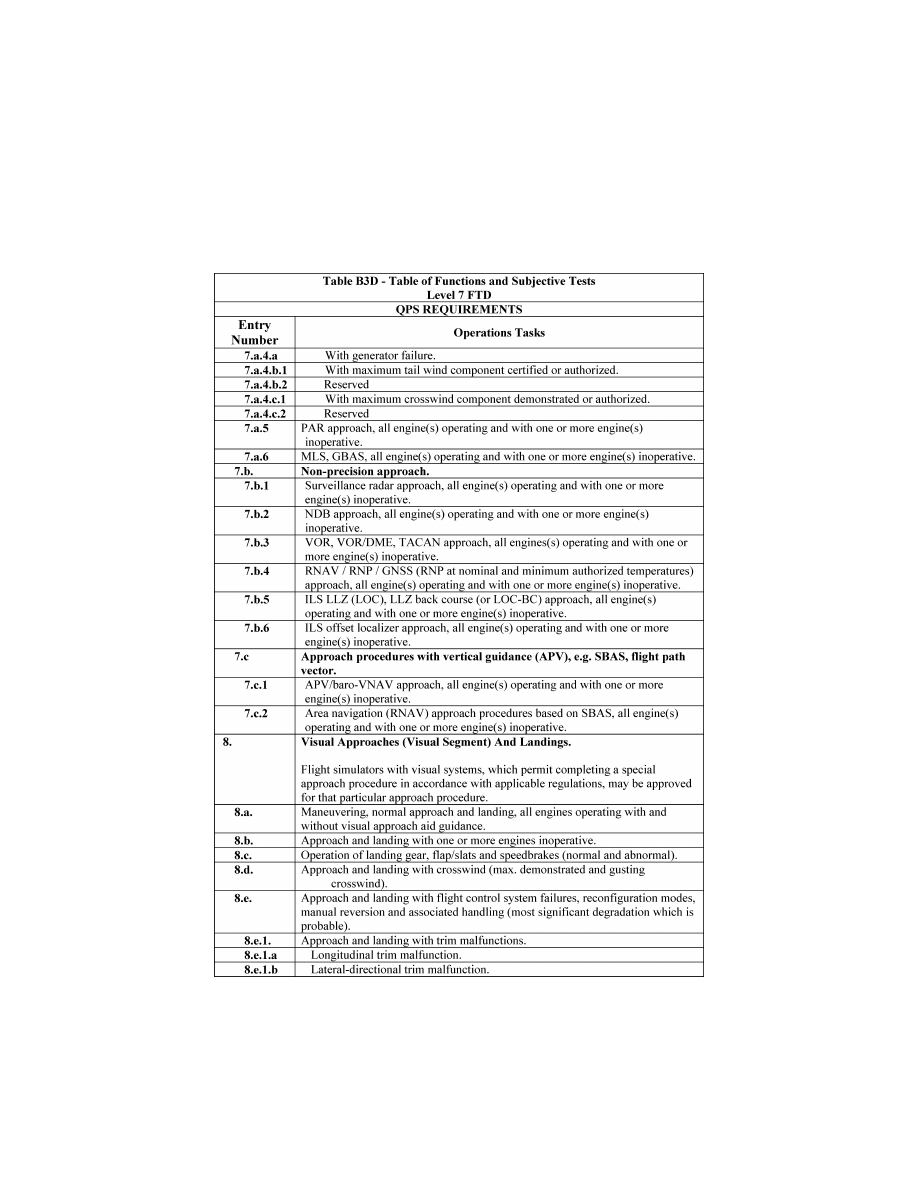
256
14 CFR Ch. I (1–1–24 Edition)
Pt. 60, App. B
VerDate Sep<11>2014
14:00 Mar 14, 2024
Jkt 262047
PO 00000
Frm 00266
Fmt 8010
Sfmt 8006
Q:\14\14V2.TXT
PC31
ER20MY16.151</GPH>
aworley on LAPBH6H6L3 with DISTILLER
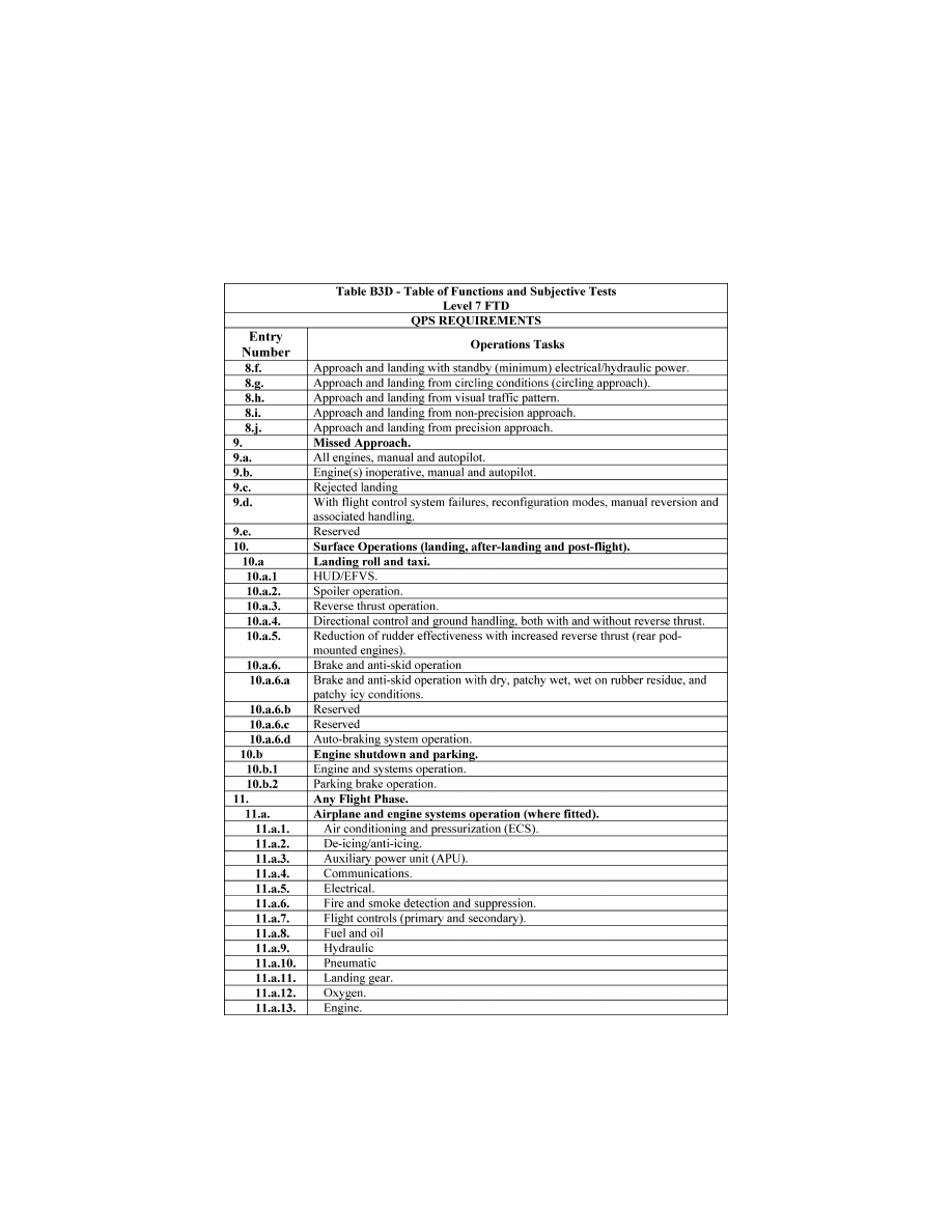
257
Federal Aviation Administration, DOT
Pt. 60, App. B
VerDate Sep<11>2014
14:00 Mar 14, 2024
Jkt 262047
PO 00000
Frm 00267
Fmt 8010
Sfmt 8006
Q:\14\14V2.TXT
PC31
ER20MY16.152</GPH>
aworley on LAPBH6H6L3 with DISTILLER
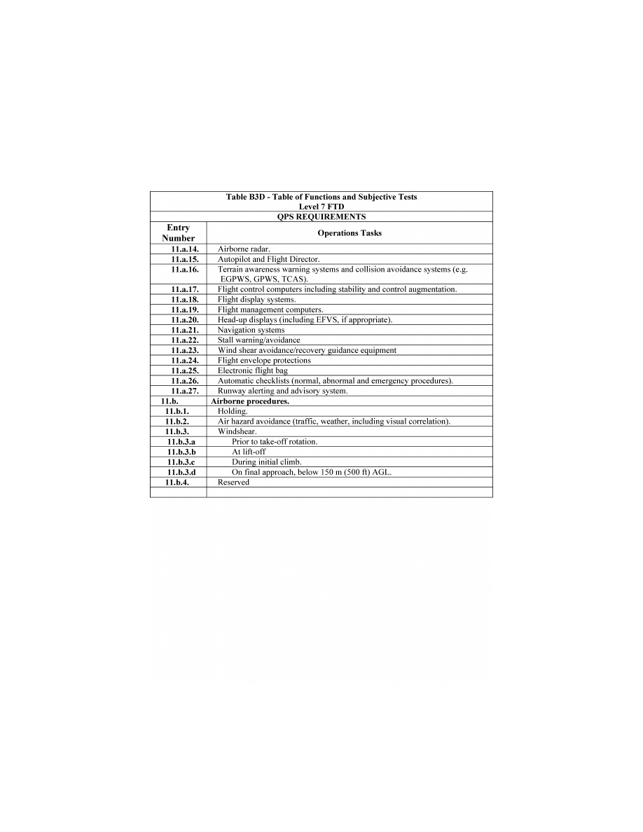
258
14 CFR Ch. I (1–1–24 Edition)
Pt. 60, App. B
VerDate Sep<11>2014
14:00 Mar 14, 2024
Jkt 262047
PO 00000
Frm 00268
Fmt 8010
Sfmt 8006
Q:\14\14V2.TXT
PC31
ER20MY16.153</GPH>
aworley on LAPBH6H6L3 with DISTILLER
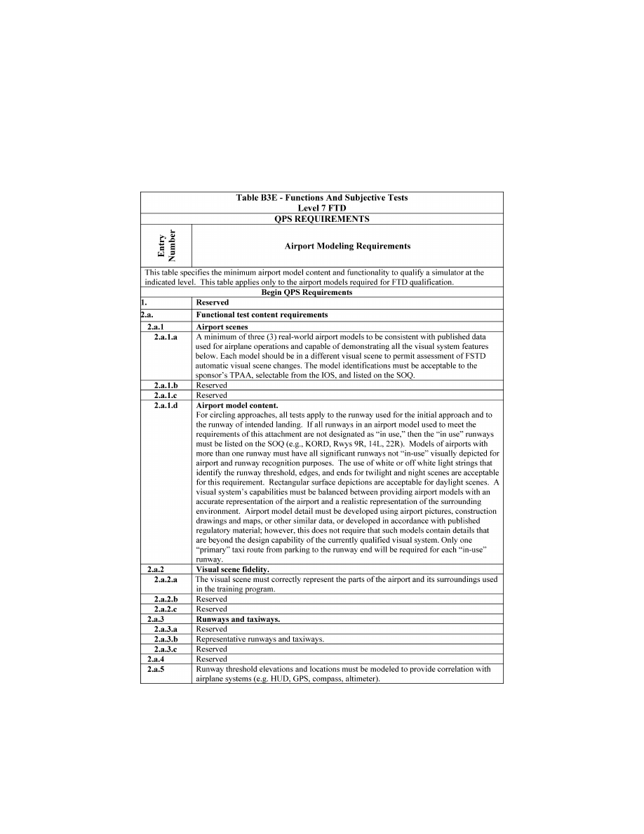
259
Federal Aviation Administration, DOT
Pt. 60, App. B
VerDate Sep<11>2014
14:00 Mar 14, 2024
Jkt 262047
PO 00000
Frm 00269
Fmt 8010
Sfmt 8006
Q:\14\14V2.TXT
PC31
ER20MY16.154</GPH>
aworley on LAPBH6H6L3 with DISTILLER
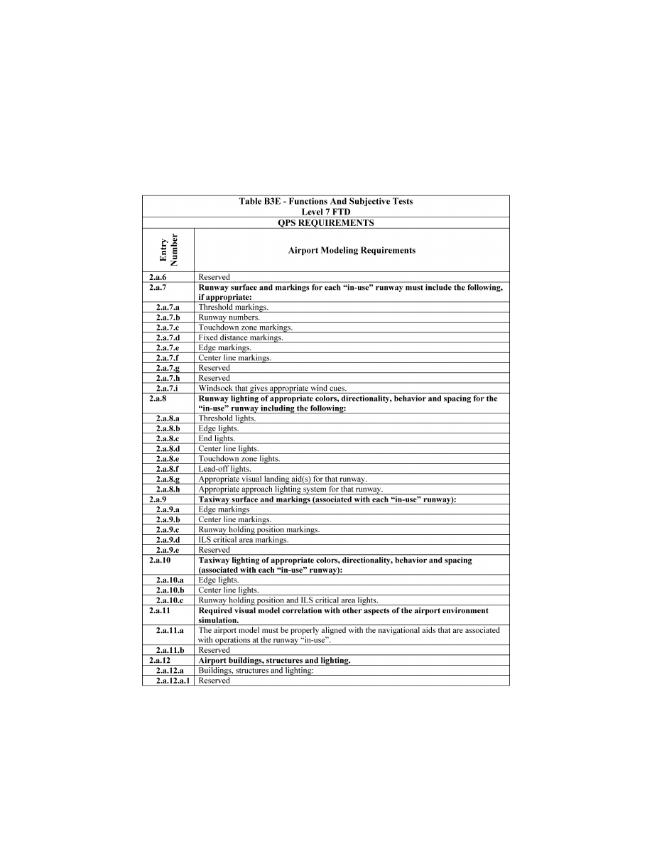
260
14 CFR Ch. I (1–1–24 Edition)
Pt. 60, App. B
VerDate Sep<11>2014
14:00 Mar 14, 2024
Jkt 262047
PO 00000
Frm 00270
Fmt 8010
Sfmt 8006
Q:\14\14V2.TXT
PC31
ER20MY16.155</GPH>
aworley on LAPBH6H6L3 with DISTILLER
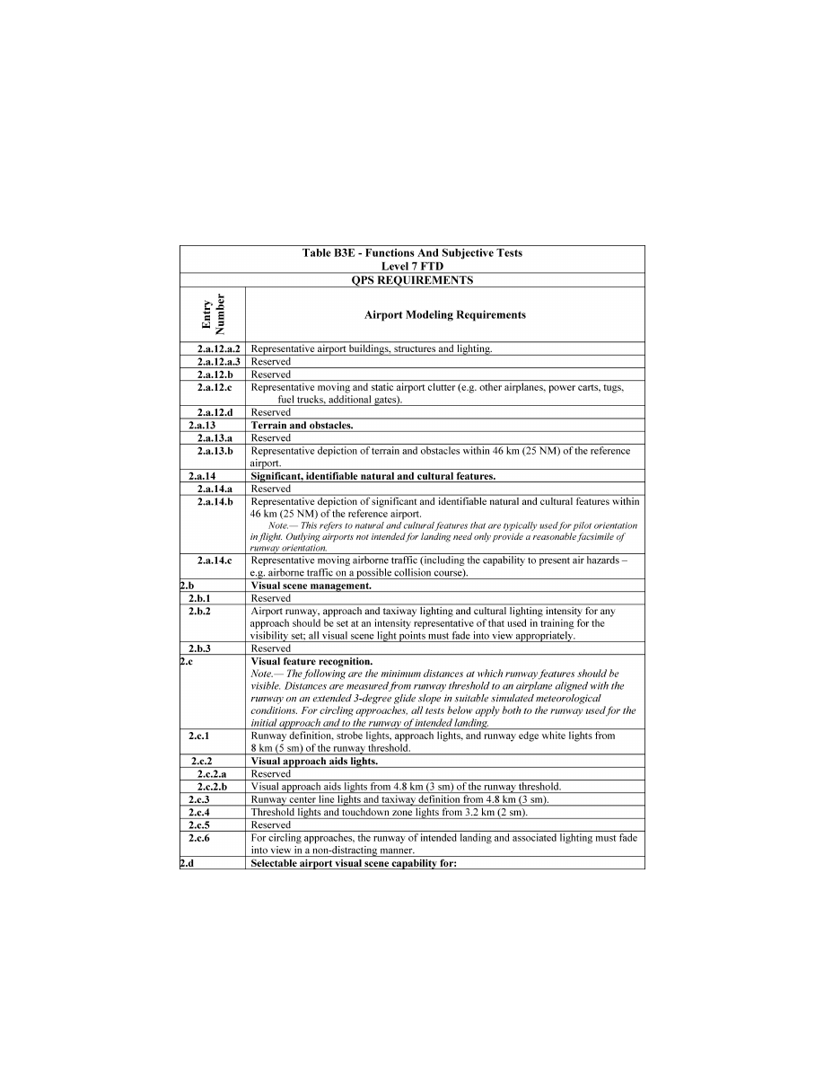
261
Federal Aviation Administration, DOT
Pt. 60, App. B
VerDate Sep<11>2014
14:00 Mar 14, 2024
Jkt 262047
PO 00000
Frm 00271
Fmt 8010
Sfmt 8006
Q:\14\14V2.TXT
PC31
ER20MY16.156</GPH>
aworley on LAPBH6H6L3 with DISTILLER
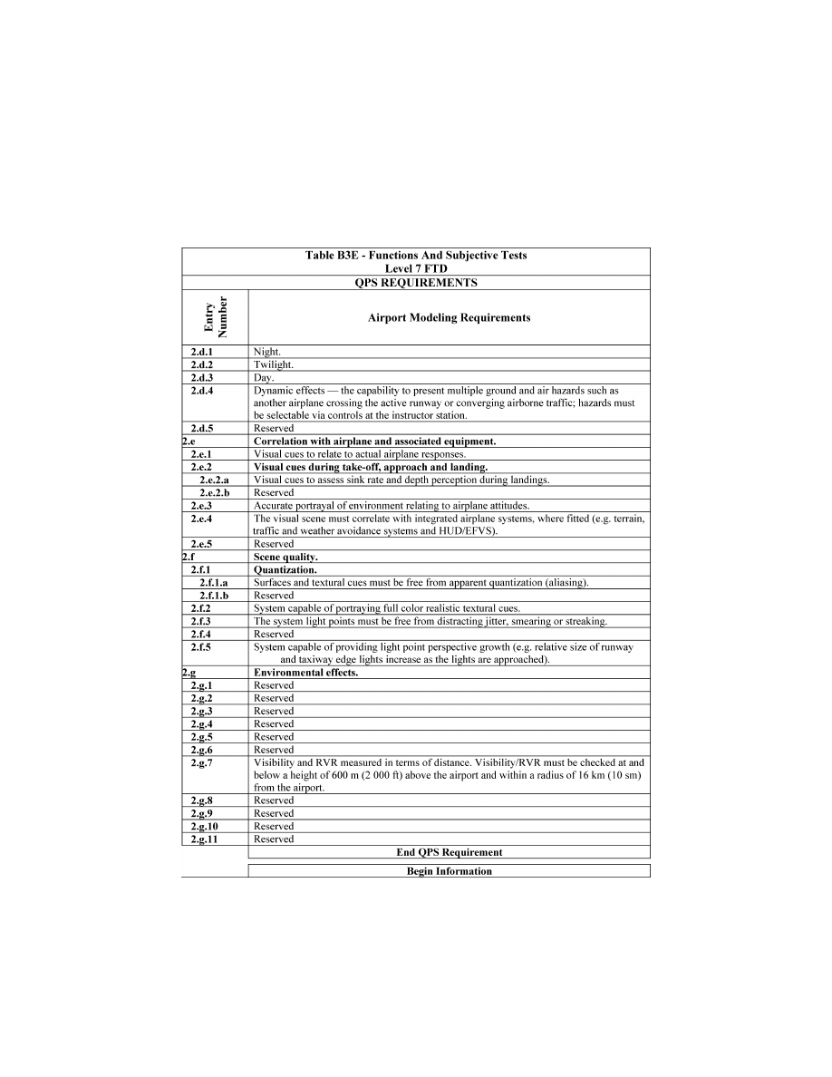
262
14 CFR Ch. I (1–1–24 Edition)
Pt. 60, App. B
VerDate Sep<11>2014
14:00 Mar 14, 2024
Jkt 262047
PO 00000
Frm 00272
Fmt 8010
Sfmt 8006
Q:\14\14V2.TXT
PC31
ER20MY16.157</GPH>
aworley on LAPBH6H6L3 with DISTILLER

263
Federal Aviation Administration, DOT
Pt. 60, App. B
VerDate Sep<11>2014
14:00 Mar 14, 2024
Jkt 262047
PO 00000
Frm 00273
Fmt 8010
Sfmt 8006
Q:\14\14V2.TXT
PC31
ER20MY16.158</GPH>
aworley on LAPBH6H6L3 with DISTILLER
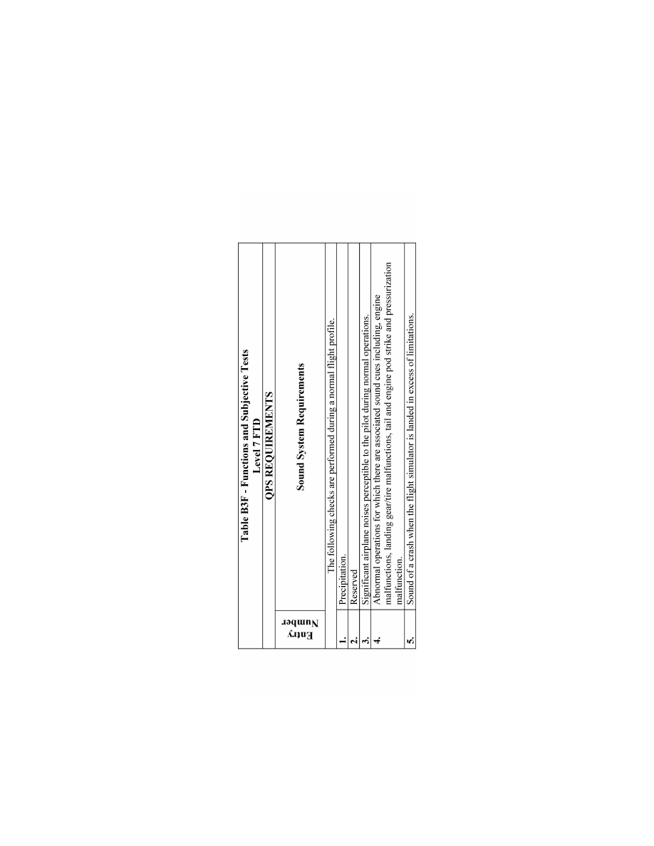
264
14 CFR Ch. I (1–1–24 Edition)
Pt. 60, App. B
VerDate Sep<11>2014
14:00 Mar 14, 2024
Jkt 262047
PO 00000
Frm 00274
Fmt 8010
Sfmt 8006
Q:\14\14V2.TXT
PC31
ER20MY16.159</GPH>
aworley on LAPBH6H6L3 with DISTILLER
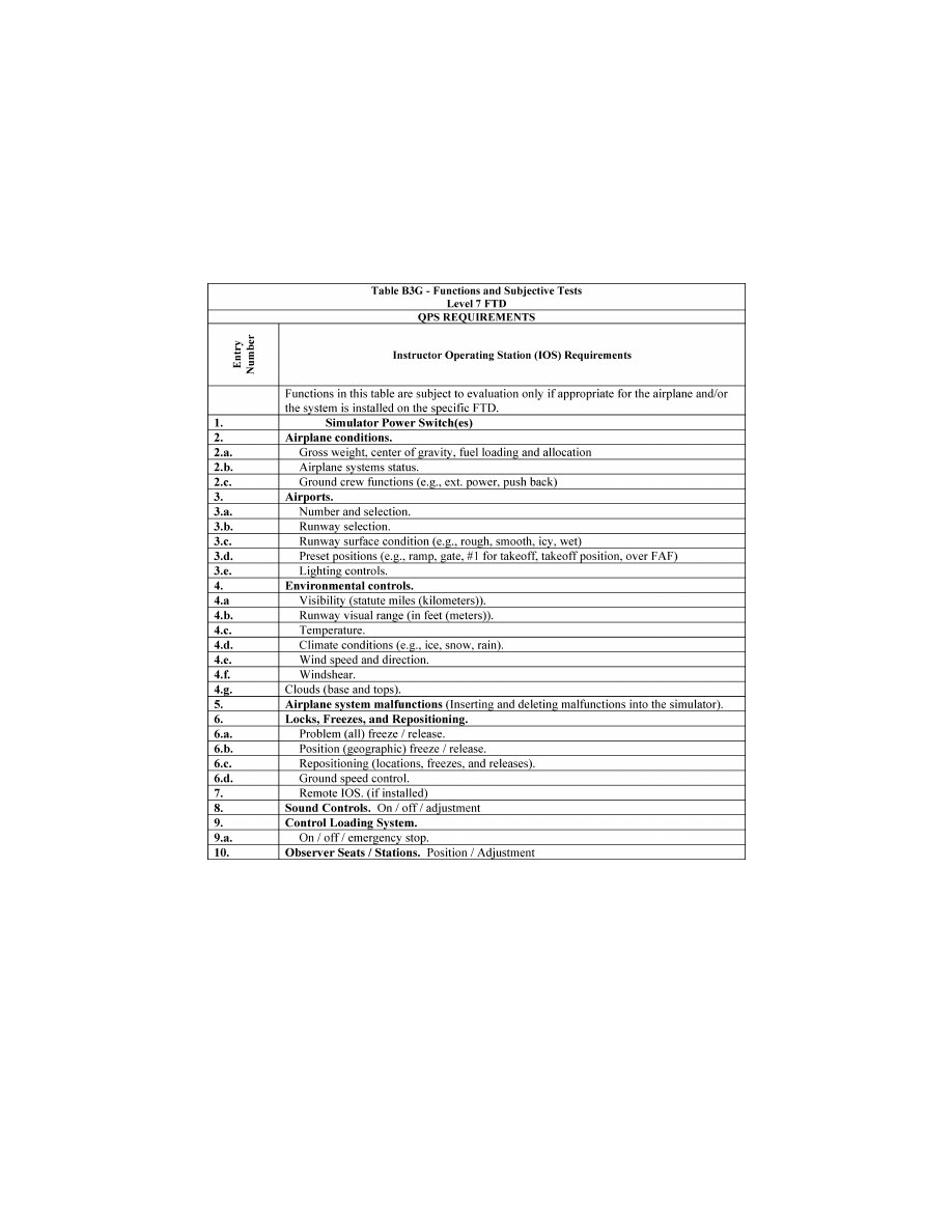
265
Federal Aviation Administration, DOT
Pt. 60, App. B
A
TTACHMENT
4
TO
A
PPENDIX
B
TO
P
ART
60—
S
AMPLE
D
OCUMENTS
llllllllllllllllllllllll
B
EGIN
I
NFORMATION
T
ABLE OF
C
ONTENTS
Title of Sample
Figure B4A
Sample Letter, Request for Ini-
tial, Upgrade, or Reinstatement Evalua-
tion
Figure B4B
Attachment: FTD Information
Form
Figure B4C
Sample Letter of Compliance
Figure B4D
Sample Qualification Test
Guide Cover Page
Figure B4E
Sample Statement of Qualifica-
tion—Certificate
Figure B4F
Sample Statement of Qualifica-
tion—Configuration List
Figure B4G
Sample Statement of Qualifica-
tion—List of Qualified Tasks
Figure B4H
[Reserved]
Figure B4I
Sample MQTG Index of Effective
FTD Directives
A
TTACHMENT
4
TO
A
PPENDIX
B
TO
P
ART
60—
F
IGURE
B4A—S
AMPLE
L
ETTER
, R
EQUEST
FOR
I
NITIAL
, U
PGRADE
,
OR
R
EINSTATEMENT
E
VALUATION
I
NFORMATION
VerDate Sep<11>2014
14:00 Mar 14, 2024
Jkt 262047
PO 00000
Frm 00275
Fmt 8010
Sfmt 8002
Q:\14\14V2.TXT
PC31
ER30MR16.117</GPH>
aworley on LAPBH6H6L3 with DISTILLER

266
14 CFR Ch. I (1–1–24 Edition)
Pt. 60, App. B
VerDate Sep<11>2014
14:00 Mar 14, 2024
Jkt 262047
PO 00000
Frm 00276
Fmt 8010
Sfmt 8006
Q:\14\14V2.TXT
PC31
ER09DE22.103</GPH>
ER09DE22.104</GPH>
aworley on LAPBH6H6L3 with DISTILLER
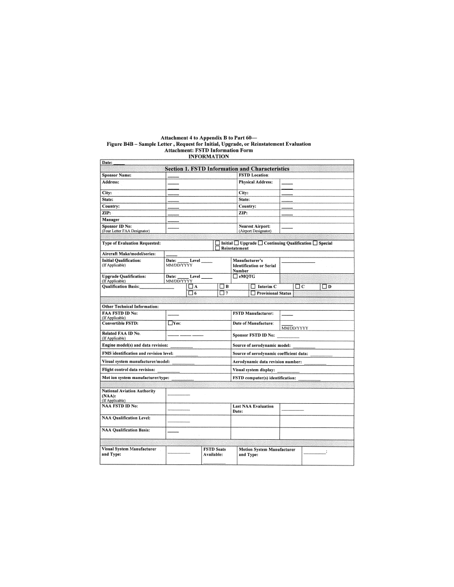
267
Federal Aviation Administration, DOT
Pt. 60, App. B
VerDate Sep<11>2014
14:00 Mar 14, 2024
Jkt 262047
PO 00000
Frm 00277
Fmt 8010
Sfmt 8006
Q:\14\14V2.TXT
PC31
ER09MY08.021</GPH>
aworley on LAPBH6H6L3 with DISTILLER
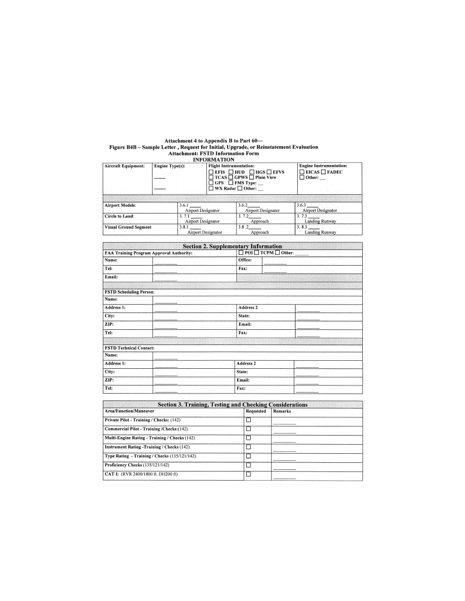
268
14 CFR Ch. I (1–1–24 Edition)
Pt. 60, App. B
VerDate Sep<11>2014
14:00 Mar 14, 2024
Jkt 262047
PO 00000
Frm 00278
Fmt 8010
Sfmt 8006
Q:\14\14V2.TXT
PC31
ER09MY08.022</GPH>
aworley on LAPBH6H6L3 with DISTILLER

269
Federal Aviation Administration, DOT
Pt. 60, App. B
A
TTACHMENT
4
TO
A
PPENDIX
B
TO
P
ART
60—
F
IGURE
B4C—S
AMPLE
L
ETTER OF
C
OMPLIANCE
I
NFORMATION
VerDate Sep<11>2014
14:00 Mar 14, 2024
Jkt 262047
PO 00000
Frm 00279
Fmt 8010
Sfmt 8002
Q:\14\14V2.TXT
PC31
ER09MY08.023</GPH>
aworley on LAPBH6H6L3 with DISTILLER

270
14 CFR Ch. I (1–1–24 Edition)
Pt. 60, App. B
A
TTACHMENT
4
TO
A
PPENDIX
B
TO
P
ART
60—
F
IGURE
B4D—S
AMPLE
Q
UALIFICATION
T
EST
G
UIDE
C
OVER
P
AGE
I
NFORMATION
VerDate Sep<11>2014
14:00 Mar 14, 2024
Jkt 262047
PO 00000
Frm 00280
Fmt 8010
Sfmt 8002
Q:\14\14V2.TXT
PC31
ER09DE22.105</GPH>
aworley on LAPBH6H6L3 with DISTILLER

271
Federal Aviation Administration, DOT
Pt. 60, App. B
A
TTACHMENT
4
TO
A
PPENDIX
B
TO
P
ART
60—
F
IGURE
B4E—S
AMPLE
S
TATEMENT OF
Q
UALI
-
FICATION
—C
ERTIFICATE
I
NFORMATION
VerDate Sep<11>2014
14:00 Mar 14, 2024
Jkt 262047
PO 00000
Frm 00281
Fmt 8010
Sfmt 8002
Q:\14\14V2.TXT
PC31
ER09DE22.106</GPH>
aworley on LAPBH6H6L3 with DISTILLER
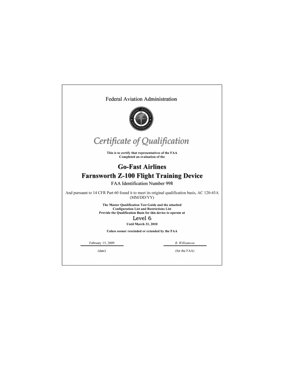
272
14 CFR Ch. I (1–1–24 Edition)
Pt. 60, App. B
VerDate Sep<11>2014
14:00 Mar 14, 2024
Jkt 262047
PO 00000
Frm 00282
Fmt 8010
Sfmt 8006
Q:\14\14V2.TXT
PC31
ER09DE22.128</GPH>
aworley on LAPBH6H6L3 with DISTILLER

273
Federal Aviation Administration, DOT
Pt. 60, App. B
VerDate Sep<11>2014
14:00 Mar 14, 2024
Jkt 262047
PO 00000
Frm 00283
Fmt 8010
Sfmt 8006
Q:\14\14V2.TXT
PC31
ER09MY08.028</GPH>
aworley on LAPBH6H6L3 with DISTILLER
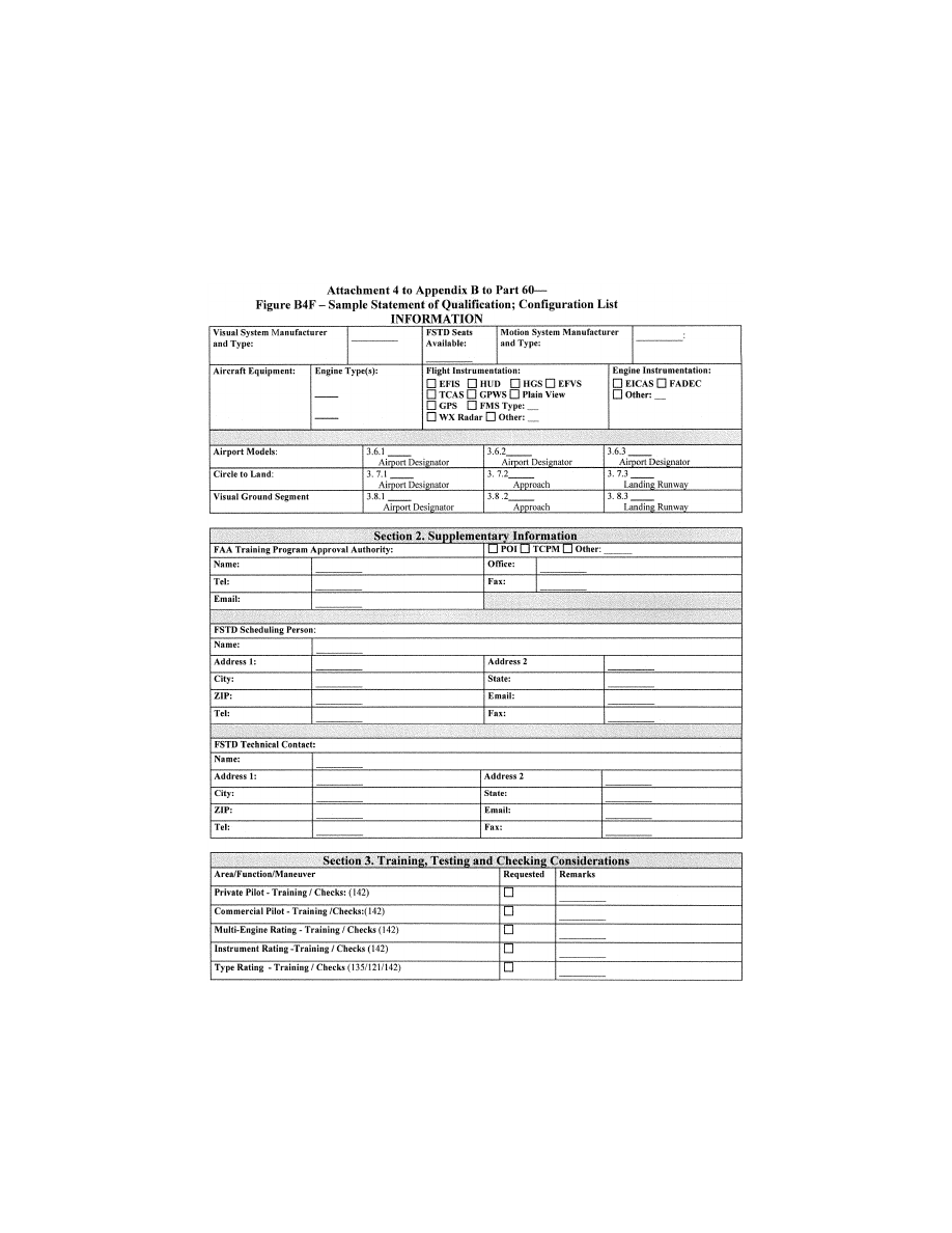
274
14 CFR Ch. I (1–1–24 Edition)
Pt. 60, App. B
VerDate Sep<11>2014
14:00 Mar 14, 2024
Jkt 262047
PO 00000
Frm 00284
Fmt 8010
Sfmt 8006
Q:\14\14V2.TXT
PC31
ER09MY08.029</GPH>
aworley on LAPBH6H6L3 with DISTILLER
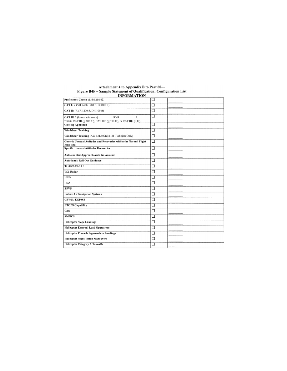
275
Federal Aviation Administration, DOT
Pt. 60, App. B
VerDate Sep<11>2014
14:00 Mar 14, 2024
Jkt 262047
PO 00000
Frm 00285
Fmt 8010
Sfmt 8006
Q:\14\14V2.TXT
PC31
ER09MY08.030</GPH>
aworley on LAPBH6H6L3 with DISTILLER

276
14 CFR Ch. I (1–1–24 Edition)
Pt. 60, App. B
A
TTACHMENT
4
TO
A
PPENDIX
B
TO
P
ART
60—F
IGURE
B4H [R
ESERVED
]
VerDate Sep<11>2014
14:00 Mar 14, 2024
Jkt 262047
PO 00000
Frm 00286
Fmt 8010
Sfmt 8026
Q:\14\14V2.TXT
PC31
ER09MY08.031</GPH>
aworley on LAPBH6H6L3 with DISTILLER

277
Federal Aviation Administration, DOT
Pt. 60, App. C
[Doc. No. FAA–2002–12461, 73 FR 26490, May 9, 2008, as amended by Docket FAA–2014–0391,
Amdt. 60–4, 81 FR 18306, 18307, 18327, and 18376, Mar. 30, 2016; 81 FR 32087, 32110, 32111, and 32165,
May 20, 2016; Amdt. 60–6, 83 FR 30275, June 27, 2018; Docket No. FAA–2022–1355, Amdt. No. 60–
7, 87 FR 75771, Dec. 9, 2022]
A
PPENDIX
C
TO
P
ART
60—Q
UALIFICATION
P
ERFORMANCE
S
TANDARDS FOR
H
EL
-
ICOPTER
F
ULL
F
LIGHT
S
IMULATORS
llllllllllllllllllllllll
B
EGIN
I
NFORMATION
This appendix establishes the standards for
Helicopter FFS evaluation and qualification.
The Flight Standards Service is responsible
for the development, application, and imple-
mentation of the standards contained within
this appendix. The procedures and criteria
specified in this appendix will be used by the
responsible Flight Standards office when
conducting helicopter FFS evaluations.
T
ABLE OF
C
ONTENTS
1. Introduction.
2. Applicability (§ 60.1) and (§ 60.2).
3. Definitions (§ 60.3).
4. Qualification Performance Standards
(§ 60.4).
5. Quality Management System (§ 60.5).
6. Sponsor Qualification Requirements
(§ 60.7).
7. Additional Responsibilities of the Sponsor
(§ 60.9).
8. FFS Use (§ 60.11).
9. FFS Objective Data Requirements (§ 60.13).
10. Special Equipment and Personnel Re-
quirements for Qualification of the FFS
(§ 60.14).
11. Initial (and Upgrade) Qualification Re-
quirements (§ 60.15).
12. Additional Qualifications for a Currently
Qualified FFS (§ 60.16).
13. Previously Qualified FFSs (§ 60.17).
14. Inspection, Continuing Qualification
Evaluation, and Maintenance Require-
ments (§ 60.19).
15. Logging FFS Discrepancies (§ 60.20).
16. Interim Qualification of FFSs for New
Helicopter Types or Models (§ 60.21).
17. Modifications to FFSs (§ 60.23).
18. Operations with Missing, Malfunctioning,
or Inoperative Components (§ 60.25).
19. Automatic Loss of Qualification and Pro-
cedures for Restoration of Qualification
(§ 60.27).
20. Other Losses of Qualification and Proce-
dures for Restoration of Qualification
(§ 60.29).
21. Record Keeping and Reporting (§ 60.31).
VerDate Sep<11>2014
14:00 Mar 14, 2024
Jkt 262047
PO 00000
Frm 00287
Fmt 8010
Sfmt 8002
Q:\14\14V2.TXT
PC31
ER09MY08.033</GPH>
aworley on LAPBH6H6L3 with DISTILLER

278
14 CFR Ch. I (1–1–24 Edition)
Pt. 60, App. C
22. Applications, Logbooks, Reports, and
Records: Fraud, Falsification, or Incor-
rect Statements (§ 60.33).
23. [Reserved]
24. [Reserved]
25. FFS Qualification on the Basis of a Bilat-
eral Aviation Safety Agreement (BASA)
(§ 60.37).
Attachment 1 to Appendix C to Part 60—Gen-
eral Simulator Requirements.
Attachment 2 to Appendix C to Part 60—FFS
Objective Tests.
Attachment 3 to Appendix C to Part 60—
Simulator Subjective Evaluation.
Attachment 4 to Appendix C to Part 60—
Sample Documents.
Attachment 5 to Appendix C to Part 60—
FSTD Directives Applicable to Heli-
copter FFSs
E
ND
I
NFORMATION
llllllllllllllllllllllll
1. I
NTRODUCTION
llllllllllllllllllllllll
B
EGIN
I
NFORMATION
a. This appendix contains background in-
formation as well as regulatory and inform-
ative material as described later in this sec-
tion. To assist the reader in determining
what areas are required and what areas are
permissive, the text in this appendix is di-
vided into two sections: ‘‘QPS Require-
ments’’ and ‘‘Information.’’ The QPS Re-
quirements sections contain details regard-
ing compliance with the part 60 rule lan-
guage. These details are regulatory, but are
found only in this appendix. The Information
sections contain material that is advisory in
nature, and designed to give the user general
information about the regulation.
b. [Reserved]
c. The responsible Flight Standards office
encourages the use of electronic media for
all communication, including any record, re-
port, request, test, or statement required by
this appendix. The electronic media used
must have adequate security provisions and
be acceptable to the responsible Flight
Standards office.
d. Related Reading References.
(1) 14 CFR part 60.
(2) 14 CFR part 61.
(3) 14 CFR part 63.
(4) 14 CFR part 119.
(5) 14 CFR part 121.
(6) 14 CFR part 125.
(7) 14 CFR part 135.
(8) 14 CFR part 141.
(9) 14 CFR part 142.
(10) AC 120–35, as amended, Flightcrew
Member Line Operational Simulations: Line-
Oriented Flight Training, Special Purpose
Operational Training, Line Operational
Evaluation.
(11) AC 120–57, as amended, Surface Move-
ment Guidance and Control System
(SMGCS).
(12) AC 120–63, as amended, Helicopter Sim-
ulator Qualification.
(13) AC 150/5300–13, as amended, Airport De-
sign.
(14) AC 150/5340–1, as amended, Standards
for Airport Markings.
(15) AC 150/5340–4, as amended, Installation
Details for Runway Centerline Touchdown
Zone Lighting Systems.
(16) AC 150/5340–19, as amended, Taxiway
Centerline Lighting System.
(17) AC 150/5340–24, as amended, Runway
and Taxiway Edge Lighting System.
(18) AC 150/5345–28, as amended, Precision
Approach Path Indicator (PAPI) Systems
(19) AC 150/5390–2, as amended, Heliport De-
sign
(20) International Air Transport Associa-
tion document, ‘‘Flight Simulator Design
and Performance Data Requirements,’’ as
amended.
(21) AC 29–2, as amended, Flight Test Guide
for Certification of Transport Category
Rotorcraft.
(22) AC 27–1, as amended, Flight Test Guide
for Certification of Normal Category Rotor-
craft.
(23) International Civil Aviation Organiza-
tion (ICAO) Manual of Criteria for the Quali-
fication of Flight Simulators, as amended.
(24) Airplane Flight Simulator Evaluation
Handbook, Volume I, as amended and Vol-
ume II, as amended, The Royal Aeronautical
Society, London, UK.
(25) FAA Airman Certification Standards
and Practical Test Standards for Airline
Transport Pilot, Type Ratings, Commercial
Pilot, and Instrument Ratings.
(26) The FAA Aeronautical Information
Manual (AIM). An electronic version of the
AIM is on the Internet at
http://www.faa.gov/
atpubs.
(27) Aeronautical Radio, Inc. (ARINC) doc-
ument number 436, titled
Guidelines For Elec-
tronic Qualification Test Guide (as amended).
(28) Aeronautical Radio, Inc. (ARINC) doc-
ument 610,
Guidance for Design and Integra-
tion of Aircraft Avionics Equipment in Simula-
tors (as amended).
E
ND
I
NFORMATION
llllllllllllllllllllllll
2. A
PPLICABILITY
(§§ 60.1
AND
60.2)
llllllllllllllllllllllll
B
EGIN
I
NFORMATION
No additional regulatory or informational
material applies to § 60.1, Applicability, or to
§ 60.2, Applicability of sponsor rules to person
who are not sponsors and who are engaged in
certain unauthorized activities.
VerDate Sep<11>2014
14:00 Mar 14, 2024
Jkt 262047
PO 00000
Frm 00288
Fmt 8010
Sfmt 8002
Q:\14\14V2.TXT
PC31
aworley on LAPBH6H6L3 with DISTILLER

279
Federal Aviation Administration, DOT
Pt. 60, App. C
E
ND
I
NFORMATION
llllllllllllllllllllllll
3. D
EFINITIONS
(§ 60.3)
llllllllllllllllllllllll
B
EGIN
I
NFORMATION
See Appendix F of this part for a list of
definitions and abbreviations from part 1 and
part 60, including the appropriate appendices
of part 60.
E
ND
I
NFORMATION
llllllllllllllllllllllll
4. Q
UALIFICATION
P
ERFORMANCE
S
TANDARDS
(§ 60.4)
llllllllllllllllllllllll
B
EGIN
I
NFORMATION
No additional regulatory or informational
material applies to § 60.4, Qualification Per-
formance Standards.
E
ND
I
NFORMATION
llllllllllllllllllllllll
5. Q
UALITY
M
ANAGEMENT
S
YSTEM
(§ 60.5)
llllllllllllllllllllllll
B
EGIN
I
NFORMATION
See Appendix E of this part for additional
regulatory and informational material re-
garding Quality Management Systems.
E
ND
I
NFORMATION
llllllllllllllllllllllll
6. S
PONSOR
Q
UALIFICATION
R
EQUIREMENTS
(§ 60.7)
llllllllllllllllllllllll
B
EGIN
I
NFORMATION
a. The intent of the language in § 60.7(b) is
to have a specific FFS, identified by the
sponsor, used at least once in an FAA-ap-
proved flight training program for the heli-
copter simulated during the 12-month period
described. The identification of the specific
FFS may change from one 12-month period
to the next 12-month period as long as that
sponsor sponsors and uses at least one FFS
at least once during the prescribed period.
There is no minimum number of hours or
minimum FFS periods required.
b. The following examples describe accept-
able operational practices:
(1) Example One.
(a) A sponsor is sponsoring a single, spe-
cific FFS for its own use, in its own facility
or elsewhere—this single FFS forms the
basis for the sponsorship. The sponsor uses
that FFS at least once in each 12-month pe-
riod in that sponsor’s FAA-approved flight
training program for the helicopter simu-
lated. This 12-month period is established ac-
cording to the following schedule:
(i) If the FFS was qualified prior to May 30,
2008, the 12-month period begins on the date
of the first continuing qualification evalua-
tion conducted in accordance with § 60.19
after May 30, 2008, and continues for each
subsequent 12-month period;
(ii) A device qualified on or after May 30,
2008, will be required to undergo an initial or
upgrade evaluation in accordance with
§ 60.15. Once the initial or upgrade evaluation
is complete, the first continuing qualifica-
tion evaluation will be conducted within 6
months. The 12 month continuing qualifica-
tion evaluation cycle begins on that date and
continues for each subsequent 12-month pe-
riod.
(b) There is no minimum number of hours
of FFS use required.
(c) The identification of the specific FFS
may change from one 12-month period to the
next 12-month period as long as that sponsor
sponsors and uses at least one FFS at least
once during the prescribed period.
(2) Example Two.
(a) A sponsor sponsors an additional num-
ber of FFSs, in its facility or elsewhere.
Each additionally sponsored FFS must be—
(i) Used by the sponsor in the sponsor’s
FAA-approved flight training program for
the helicopter simulated (as described in
§ 60.7(d)(1)); or
(ii) Used by another FAA certificate holder
in that other certificate holder’s FAA-ap-
proved flight training program for the heli-
copter simulated (as described in § 60.7(d)(1)).
This 12-month period is established in the
same manner as in example one; or
(iii) Provided a statement each year from a
qualified pilot, (after having flown the heli-
copter, not the subject FFS or another FFS,
during the preceding 12-month period) stat-
ing that the subject FFS’s performance and
handling qualities represent the helicopter
(as described in § 60.7(d)(2)). This statement is
provided at least once in each 12-month pe-
riod established in the same manner as in ex-
ample one.
(b) There is no minimum number of hours
of FFS use required.
(3) Example Three.
(a) A sponsor in New York (in this exam-
ple, a Part 142 certificate holder) establishes
‘‘satellite’’ training centers in Chicago and
Moscow.
(b) The satellite function means that the
Chicago and Moscow centers must operate
under the New York center’s certificate (in
accordance with all of the New York center’s
practices, procedures, and policies;
e.g., in-
structor and/or technician training/checking
requirements, record keeping, QMS pro-
gram).
VerDate Sep<11>2014
14:00 Mar 14, 2024
Jkt 262047
PO 00000
Frm 00289
Fmt 8010
Sfmt 8002
Q:\14\14V2.TXT
PC31
aworley on LAPBH6H6L3 with DISTILLER

280
14 CFR Ch. I (1–1–24 Edition)
Pt. 60, App. C
(c) All of the FFSs in the Chicago and Mos-
cow centers could be dry-leased (
i.e., the cer-
tificate holder does not have and use FAA-
approved flight training programs for the
FFSs in the Chicago and Moscow centers) be-
cause—
(i) Each FFS in the Chicago center and
each FFS in the Moscow center is used at
least once each 12-month period by another
FAA certificate holder in that other certifi-
cate holder’s FAA-approved flight training
program for the helicopter (as described in
§ 60.7(d)(1)); OR
(ii) A statement is obtained from a quali-
fied pilot (having flown the helicopter, not
the subject FFS or another FFS during the
preceding 12-month period) stating that the
performance and handling qualities of each
FFS in the Chicago and Moscow centers rep-
resents the helicopter (as described in
§ 60.7(d)(2)).
E
ND
I
NFORMATION
llllllllllllllllllllllll
7. Additional Responsibilities of the Spon-
sor (§ 60.9).
B
EGIN
I
NFORMATION
The phrase ‘‘as soon as practicable’’ in
§ 60.9(a) means without unnecessarily dis-
rupting or delaying beyond a reasonable
time the training, evaluation, or experience
being conducted in the FFS.
E
ND
I
NFORMATION
llllllllllllllllllllllll
8. FFS U
SE
(§ 60.11)
llllllllllllllllllllllll
B
EGIN
I
NFORMATION
No additional regulatory or informational
material applies to § 60.11, FFS Use.
E
ND
I
NFORMATION
llllllllllllllllllllllll
9. FFS O
BJECTIVE
D
ATA
R
EQUIREMENTS
(§ 60.13)
llllllllllllllllllllllll
B
EGIN
QPS R
EQUIREMENTS
a. Flight test data used to validate FFS
performance and handling qualities must
have been gathered in accordance with a
flight test program containing the following:
(1) A flight test plan consisting of:
(a) The maneuvers and procedures required
for aircraft certification and simulation pro-
gramming and validation
(b) For each maneuver or procedure—
(i) The procedures and control input the
flight test pilot and/or engineer used.
(ii) The atmospheric and environmental
conditions.
(iii) The initial flight conditions.
(iv) The helicopter configuration, includ-
ing weight and center of gravity.
(v) The data to be gathered.
(vi) All other information necessary to
recreate the flight test conditions in the
FFS.
(2) Appropriately qualified flight test per-
sonnel.
(3) An understanding of the accuracy of the
data to be gathered using appropriate alter-
native data sources, procedures, and instru-
mentation that is traceable to a recognized
standard as described in Attachment 2, Table
C2D of this appendix.
(4) Appropriate and sufficient data acquisi-
tion equipment or system(s), including ap-
propriate data reduction and analysis meth-
ods and techniques, acceptable to the FAA’s
Aircraft Certification Service.
b. The data, regardless of source, must be
presented:
(1) In a format that supports the FFS vali-
dation process;
(2) In a manner that is clearly readable and
annotated correctly and completely;
(3) With resolution sufficient to determine
compliance with the tolerances set forth in
Attachment 2, Table C2A of this appendix.
(4) With any necessary instructions or
other details provided, such as Stability
Augmentation System (SAS) or throttle po-
sition; and
(5) Without alteration, adjustments, or
bias. Data may be corrected to address
known data calibration errors provided that
an explanation of the methods used to cor-
rect the errors appears in the QTG. The cor-
rected data may be re-scaled, digitized, or
otherwise manipulated to fit the desired
presentation.
c. After completion of any additional flight
test, a flight test report must be submitted
in support of the validation data. The report
must contain sufficient data and rationale to
support qualification of the FFS at the level
requested.
d. As required by § 60.13(f), the sponsor
must notify the responsible Flight Standards
office when it becomes aware that an addi-
tion to, an amendment to, or a revision of
data that may relate to FFS performance or
handling characteristics is available. The
data referred to in this paragraph is data
used to validate the performance, handling
qualities, or other characteristics of the air-
craft, including data related to any relevant
changes occurring after the type certificate
was issued. The sponsor must—
(1) Within 10 calendar days, notify the re-
sponsible Flight Standards office of the ex-
istence of this data; and
(2) Within 45 calendar days, notify the re-
sponsible Flight Standards office of—
(a) The schedule to incorporate this data
into the FFS; or
VerDate Sep<11>2014
14:00 Mar 14, 2024
Jkt 262047
PO 00000
Frm 00290
Fmt 8010
Sfmt 8002
Q:\14\14V2.TXT
PC31
aworley on LAPBH6H6L3 with DISTILLER

281
Federal Aviation Administration, DOT
Pt. 60, App. C
(b) The reason for not incorporating this
data into the FFS.
e. In those cases where the objective test
results authorize a ‘‘snapshot test’’ or a ‘‘se-
ries of snapshot test results’’ in lieu of a
time-history result, the sponsor or other
data provider must ensure that a steady
state condition exists at the instant of time
captured by the ‘‘snapshot.’’ The steady
state condition must exist from 4 seconds
prior to, through 1 second following, the in-
stant of time captured by the snap shot.
E
ND
QPS R
EQUIREMENTS
llllllllllllllllllllllll
B
EGIN
I
NFORMATION
f. The FFS sponsor is encouraged to main-
tain a liaison with the manufacturer of the
aircraft being simulated (or with the holder
of the aircraft type certificate for the air-
craft being simulated if the manufacturer is
no longer in business), and, if appropriate,
with the person who supplied the aircraft
data package for the FFS in order to facili-
tate the notification required by § 60.13(f).
g. It is the intent of the responsible Flight
Standards office that for new aircraft enter-
ing service, at a point well in advance of
preparation of the QTG, the sponsor should
submit to the responsible Flight Standards
office for approval, a descriptive document
(see Table C2D, Sample Validation Data
Roadmap for Helicopters) containing the
plan for acquiring the validation data, in-
cluding data sources. This document should
clearly identify sources of data for all re-
quired tests, a description of the validity of
these data for a specific engine type and
thrust rating configuration, and the revision
levels of all avionics affecting the perform-
ance or flying qualities of the aircraft. Addi-
tionally, this document should provide other
information, such as the rationale or expla-
nation for cases where data or data param-
eters are missing, instances where engineer-
ing simulation data are used or where flight
test methods require further explanations. It
should also provide a brief narrative describ-
ing the cause and effect of any deviation
from data requirements. The aircraft manu-
facturer may provide this document.
h. There is no requirement for any flight
test data supplier to submit a flight test
plan or program prior to gathering flight
test data. However, the responsible Flight
Standards office notes that inexperienced
data gatherers often provide data that is ir-
relevant, improperly marked, or lacking ade-
quate justification for selection. Other prob-
lems include inadequate information regard-
ing initial conditions or test maneuvers. The
responsible Flight Standards office has been
forced to refuse these data submissions as
validation data for an FFS evaluation. It is
for this reason that the responsible Flight
Standards office recommends that any data
supplier not previously experienced in this
area review the data necessary for program-
ming and for validating the performance of
the FFS, and discuss the flight test plan an-
ticipated for acquiring such data with the re-
sponsible Flight Standards office well in ad-
vance of commencing the flight tests.
i. The responsible Flight Standards office
will consider, on a case-by-case basis, wheth-
er to approve supplemental validation data
derived from flight data recording systems
such as a Quick Access Recorder or Flight
Data Recorder.
E
ND
I
NFORMATION
10. S
PECIAL
E
QUIPMENT AND
P
ERSONNEL
R
E
-
QUIREMENTS FOR
Q
UALIFICATION OF THE
FFS
(§ 60.14)
llllllllllllllllllllllll
B
EGIN
I
NFORMATION
a. In the event that the responsible Flight
Standards office determines that special
equipment or specifically qualified persons
will be required to conduct an evaluation,
the responsible Flight Standards office will
make every attempt to notify the sponsor at
least one (1) week, but in no case less than 72
hours, in advance of the evaluation. Exam-
ples of special equipment include spot
photometers, flight control measurement de-
vices, and sound analyzers. Examples of spe-
cially qualified personnel include individuals
specifically qualified to install or use any
special equipment when its use is required.
b. Examples of a special evaluation include
an evaluation conducted after an FFS is
moved, at the request of the TPAA, or as a
result of comments received from users of
the FFS that raise questions about the con-
tinued qualification or use of the FFS.
E
ND
I
NFORMATION
llllllllllllllllllllllll
11. I
NITIAL
(
AND
U
PGRADE
) Q
UALIFICATION
R
EQUIREMENTS
(§ 60.15)
llllllllllllllllllllllll
B
EGIN
QPS R
EQUIREMENTS
a. In order to be qualified at a particular
qualification level, the FFS must:
(1) Meet the general requirements listed in
Attachment 1 of this appendix;
(2) Meet the objective testing requirements
listed in Attachment 2 of this appendix; and
(3) Satisfactorily accomplish the subjec-
tive tests listed in Attachment 3 of this ap-
pendix.
b. The request described in § 60.15(a) must
include all of the following:
(1) A statement that the FFS meets all of
the applicable provisions of this part and all
applicable provisions of the QPS.
VerDate Sep<11>2014
14:00 Mar 14, 2024
Jkt 262047
PO 00000
Frm 00291
Fmt 8010
Sfmt 8002
Q:\14\14V2.TXT
PC31
aworley on LAPBH6H6L3 with DISTILLER

282
14 CFR Ch. I (1–1–24 Edition)
Pt. 60, App. C
(2) A confirmation that the sponsor will
forward to the responsible Flight Standards
office the statement described in § 60.15(b) in
such time as to be received no later than 5
business days prior to the scheduled evalua-
tion and may be forwarded to the responsible
Flight Standards office via traditional or
electronic means.
(3) A QTG, acceptable to the responsible
Flight Standards office, that includes all of
the following:
(a) Objective data obtained from aircraft
testing or another approved source.
(b) Correlating objective test results ob-
tained from the performance of the FFS as
prescribed in the appropriate QPS.
(c) The result of FFS subjective tests pre-
scribed in the appropriate QPS.
(d) A description of the equipment nec-
essary to perform the evaluation for initial
qualification and the continuing qualifica-
tion evaluations.
c. The QTG described in paragraph (a)(3) of
this section, must provide the documented
proof of compliance with the simulator ob-
jective tests in Attachment 2, Table C2A of
this appendix.
d. The QTG is prepared and submitted by
the sponsor, or the sponsor’s agent on behalf
of the sponsor, to the responsible Flight
Standards office for review and approval, and
must include, for each objective test:
(1) Parameters, tolerances, and flight con-
ditions.
(2) Pertinent and complete instructions for
the conduct of automatic and manual tests.
(3) A means of comparing the FFS test re-
sults to the objective data.
(4) Any other information as necessary, to
assist in the evaluation of the test results.
(5) Other information appropriate to the
qualification level of the FFS.
e. The QTG described in paragraphs (a)(3)
and (b) of this section, must include the fol-
lowing:
(1) A QTG cover page with sponsor and
FAA approval signature blocks (see Attach-
ment 4, Figure C4C, of this appendix, for a
sample QTG cover page).
(2) A continuing qualification evaluation
schedule requirements page. This page will
be used by the responsible Flight Standards
office to establish and record the frequency
with which continuing qualification evalua-
tions must be conducted and any subsequent
changes that may be determined by the re-
sponsible Flight Standards office in accord-
ance with § 60.19. See Attachment 4 of this
appendix, Figure C4G, for a sample Con-
tinuing Qualification Evaluation Require-
ments page.
(3) An FFS information page that provides
the information listed in this paragraph (see
Attachment 4, Figure C4B, of this appendix
for a sample FFS information page). For
convertible FFSs, the sponsor must submit a
separate page for each configuration of the
FFS.
(a) The sponsor’s FFS identification num-
ber or code.
(b) The helicopter model and series being
simulated.
(c) The aerodynamic data revision number
or reference.
(d) The source of the basic aerodynamic
model and the aerodynamic coefficient data
used to modify the basic model.
(e) The engine model(s) and its data revi-
sion number or reference.
(f) The flight control data revision number
or reference.
(g) The flight management system identi-
fication and revision level.
(h) The FFS model and manufacturer.
(i) The date of FFS manufacture.
(j) The FFS computer identification.
(k) The visual system model and manufac-
turer, including display type.
(l) The motion system type and manufac-
turer, including degrees of freedom.
(4) A Table of Contents.
(5) A log of revisions and a list of effective
pages.
(6) List of all relevant data references.
(7) A glossary of terms and symbols used
(including sign conventions and units).
(8) Statements of compliance and capa-
bility (SOCs) with certain requirements.
(9) Recording procedures or equipment re-
quired to accomplish the objective tests.
(10) The following information for each ob-
jective test designated in Attachment 2 of
this appendix, Table C2A, as applicable to
the qualification level sought:
(a) Name of the test.
(b) Objective of the test.
(c) Initial conditions.
(d) Manual test procedures.
(e) Automatic test procedures (if applica-
ble).
(f) Method for evaluating FFS objective
test results.
(g) List of all relevant parameters driven
or constrained during the automatically con-
ducted test(s).
(h) List of all relevant parameters driven
or constrained during the manually con-
ducted test(s).
(i) Tolerances for relevant parameters.
(j) Source of Validation Data (document
and page number).
(k) Copy of the Validation Data (if located
in a separate binder, a cross reference for the
identification and page number for pertinent
data location must be provided).
(l) Simulator Objective Test Results as ob-
tained by the sponsor. Each test result must
reflect the date completed and must be
clearly labeled as a product of the device
being tested.
f. A convertible FFS is addressed as a sepa-
rate FFS for each model and series heli-
copter to which it will be converted and for
VerDate Sep<11>2014
14:00 Mar 14, 2024
Jkt 262047
PO 00000
Frm 00292
Fmt 8010
Sfmt 8002
Q:\14\14V2.TXT
PC31
aworley on LAPBH6H6L3 with DISTILLER

283
Federal Aviation Administration, DOT
Pt. 60, App. C
the FAA qualification level sought. If a spon-
sor seeks qualification for two or more mod-
els of a helicopter type using a convertible
FFS, the sponsor must submit a QTG for
each helicopter model, or a QTG for the first
helicopter model and a supplement to that
QTG for each additional helicopter model.
The responsible Flight Standards office will
conduct evaluations for each helicopter
model.
g. Form and manner of presentation of ob-
jective test results in the QTG:
(1) The sponsor’s FFS test results must be
recorded in a manner acceptable to the re-
sponsible Flight Standards office, that al-
lows easy comparison of the FFS test results
to the validation data (e.g., use of a multi-
channel recorder, line printer, cross plotting,
overlays, transparencies).
(2) FFS results must be labeled using ter-
minology common to helicopter parameters
as opposed to computer software identifica-
tions.
(3) Validation data documents included in
a QTG may be photographically reduced only
if such reduction will not alter the graphic
scaling or cause difficulties in scale interpre-
tation or resolution.
(4) Scaling on graphical presentations
must provide the resolution necessary to
evaluate the parameters shown in Attach-
ment 2, Table C2A of this appendix.
(5) Tests involving time histories, data
sheets (or transparencies thereof) and FFS
test results must be clearly marked with ap-
propriate reference points to ensure an accu-
rate comparison between the FFS and the
helicopter with respect to time. Time his-
tories recorded via a line printer are to be
clearly identified for cross plotting on the
helicopter data. Over-plots must not obscure
the reference data.
h. The sponsor may elect to complete the
QTG objective and subjective tests at the
manufacturer’s facility or at the sponsor’s
training facility. If the tests are conducted
at the manufacturer’s facility, the sponsor
must repeat at least one-third of the tests at
the sponsor’s training facility in order to
substantiate FFS performance. The QTG
must be clearly annotated to indicate when
and where each test was accomplished. Tests
conducted at the manufacturer’s facility and
at the sponsor’s training facility must be
conducted after the FFS is assembled with
systems and sub-systems functional and op-
erating in an interactive manner. The test
results must be submitted to the responsible
Flight Standards office.
i. The sponsor must maintain a copy of the
MQTG at the FFS location.
j. All FFSs for which the initial qualifica-
tion is conducted after May 30, 2014, must
have an electronic MQTG (EmqTG) including
all objective data obtained from helicopter
testing, or another approved source (refor-
matted or digitized), together with corre-
lating objective test results obtained from
the performance of the FFS (reformatted or
digitized) as prescribed in this appendix. ThE
EmqTG must also contain the general FFS
performance or demonstration results (refor-
matted or digitized) prescribed in this appen-
dix, and a description of the equipment nec-
essary to perform the initial qualification
evaluation and the continuing qualification
evaluations. ThE EmqTG must include the
original validation data used to validate
FFS performance and handling qualities in
either the original digitized format from the
data supplier or an electronic scan of the
original time-history plots that were pro-
vided by the data supplier. A copy of thE
EmqTG must be provided to the responsible
Flight Standards office.
k. All other FFSs not covered in subpara-
graph ‘‘j’’ must have an electronic copy of
the MQTG by May 30, 2014. An electronic
copy of the MQTG must be provided to the
responsible Flight Standards office. This
may be provided by an electronic scan pre-
sented in a Portable Document File (PDF),
or similar format acceptable to the respon-
sible Flight Standards office.
l. During the initial (or upgrade) qualifica-
tion evaluation conducted by the responsible
Flight Standards office, the sponsor must
also provide a person who is a user of the de-
vice (e.g., a qualified pilot or instructor pilot
with flight time experience in that aircraft)
and knowledgeable about the operation of
the aircraft and the operation of the FFS.
E
ND
QPS R
EQUIREMENTS
llllllllllllllllllllllll
B
EGIN
I
NFORMATION
m. Only those FFSs that are sponsored by
a certificate holder as defined in Appendix F
of this part will be evaluated by the respon-
sible Flight Standards office. However, other
FFS evaluations may be conducted on a
case-by-case basis as the Administrator
deems appropriate, but only in accordance
with applicable agreements.
n. The responsible Flight Standards office
will conduct an evaluation for each configu-
ration, and each FFS must be evaluated as
completely as possible. To ensure a thorough
and uniform evaluation, each FFS is sub-
jected to the general simulator requirements
in Attachment 1 of this appendix, the objec-
tive tests listed in Attachment 2 of this ap-
pendix, and the subjective tests listed in At-
tachment 3 of this appendix. The evaluations
described herein will include, but not nec-
essarily be limited to the following:
(1) Helicopter responses, including longitu-
dinal and lateral-directional control re-
sponses (see Attachment 2 of this appendix).
VerDate Sep<11>2014
14:00 Mar 14, 2024
Jkt 262047
PO 00000
Frm 00293
Fmt 8010
Sfmt 8002
Q:\14\14V2.TXT
PC31
aworley on LAPBH6H6L3 with DISTILLER

284
14 CFR Ch. I (1–1–24 Edition)
Pt. 60, App. C
(2) Performance in authorized portions of
the simulated helicopter’s operating enve-
lope, to include tasks evaluated by the re-
sponsible Flight Standards office in the
areas of surface operations, takeoff, climb,
cruise, descent, approach, and landing as
well as abnormal and emergency operations
(see Attachment 2 of this appendix).
(3) Control checks (see Attachment 1 and
Attachment 2 of this appendix).
(4) Flight deck configuration (see Attach-
ment 1 of this appendix).
(5) Pilot, flight engineer, and instructor
station functions checks (see Attachment 1
and Attachment 3 of this appendix).
(6) Helicopter systems and sub-systems (as
appropriate) as compared to the helicopter
simulated (see Attachment 1 and Attach-
ment 3 of this appendix).
(7) FFS systems and sub-systems, includ-
ing force cueing (motion), visual, and aural
(sound) systems, as appropriate (see Attach-
ment 1 and Attachment 2 of this appendix).
(8) Certain additional requirements, de-
pending upon the qualification level sought,
including equipment or circumstances that
may become hazardous to the occupants. The
sponsor may be subject to Occupational
Safety and Health Administration require-
ments.
o. The responsible Flight Standards office
administers the objective and subjective
tests, which includes an examination of func-
tions. The tests include a qualitative assess-
ment of the FFS by a pilot from the respon-
sible Flight Standards office. The evaluation
team leader may assign other qualified per-
sonnel to assist in accomplishing the func-
tions examination and/or the objective and
subjective tests performed during an evalua-
tion when required.
(1) Objective tests provide a basis for meas-
uring and evaluating FFS performance and
determining compliance with the require-
ments of this part.
(2) Subjective tests provide a basis for:
(a) Evaluating the capability of the FFS to
perform over a typical utilization period;
(b) Determining that the FFS satisfac-
torily simulates each required task;
(c) Verifying correct operation of the FFS
controls, instruments, and systems; and
(d) Demonstrating compliance with the re-
quirements of this part.
p. The tolerances for the test parameters
listed in Attachment 2 of this appendix re-
flect the range of tolerances acceptable to
the responsible Flight Standards office for
FFS validation and are not to be confused
with design tolerances specified for FFS
manufacture. In making decisions regarding
tests and test results, the responsible Flight
Standards office relies on the use of oper-
ational and engineering judgment in the ap-
plication of data (including consideration of
the way in which the flight test was flown
and way the data was gathered and applied),
data presentations, and the applicable toler-
ances for each test.
q. In addition to the scheduled continuing
qualification evaluation, each FFS is subject
to evaluations conducted by the responsible
Flight Standards office at any time without
prior notification to the sponsor. Such eval-
uations would be accomplished in a normal
manner (i.e., requiring exclusive use of the
FFS for the conduct of objective and subjec-
tive tests and an examination of functions) if
the FFS is not being used for flight crew-
member training, testing, or checking. How-
ever, if the FFS were being used, the evalua-
tion would be conducted in a non-exclusive
manner. This non-exclusive evaluation will
be conducted by the FFS evaluator accom-
panying the check airman, instructor, Air-
crew Program Designee (APD), or FAA in-
spector aboard the FFS along with the stu-
dent(s) and observing the operation of the
FFS during the training, testing, or check-
ing activities.
r. Problems with objective test results are
handled as follows:
(1) If a problem with an objective test re-
sult is detected by the evaluation team dur-
ing an evaluation, the test may be repeated
or the QTG may be amended.
(2) If it is determined that the results of an
objective test do not support the level re-
quested but do support a lower level, the re-
sponsible Flight Standards office may qual-
ify the FFS at that lower level. For example,
if a Level D evaluation is requested and the
FFS fails to meet sound test tolerances, it
could be qualified at Level C.
s. After an FFS is successfully evaluated,
the responsible Flight Standards office
issues a certificate of qualification (COQ) to
the sponsor. The responsible Flight Stand-
ards office recommends the FFS to the
TPAA, who will approve the FFS for use in
a flight training program. The COQ will be
issued at the satisfactory conclusion of the
initial or continuing qualification evalua-
tion and will list the tasks for which the
FFS is qualified, referencing the tasks de-
scribed in Table C1B in Attachment 1 of this
appendix. However, it is the sponsor’s re-
sponsibility to obtain TPAA approval prior
to using the FFS in an FAA-approved flight
training program.
t. Under normal circumstances, the respon-
sible Flight Standards office establishes a
date for the initial or upgrade evaluation
within ten (10) working days after deter-
mining that a complete QTG is acceptable.
Unusual circumstances may warrant estab-
lishing an evaluation date before this deter-
mination is made. A sponsor may schedule
an evaluation date as early as 6 months in
advance. However, there may be a delay of 45
days or more in rescheduling and completing
the evaluation if the sponsor is unable to
meet the scheduled date. See Attachment 4,
VerDate Sep<11>2014
14:00 Mar 14, 2024
Jkt 262047
PO 00000
Frm 00294
Fmt 8010
Sfmt 8002
Q:\14\14V2.TXT
PC31
aworley on LAPBH6H6L3 with DISTILLER

285
Federal Aviation Administration, DOT
Pt. 60, App. C
of this appendix, Figure C4A, Sample Re-
quest for Initial, Upgrade, or Reinstatement
Evaluation.
u. The numbering system used for objec-
tive test results in the QTG should closely
follow the numbering system set out in At-
tachment 2, FFS Objective Tests, Table C2A
of this appendix.
v. Contact the responsible Flight Stand-
ards office for additional information regard-
ing the preferred qualifications of pilots used
to meet the requirements of § 60.15(d).
w. Examples of the exclusions for which
the FFS might not have been subjectively
tested by the sponsor or the responsible
Flight Standards office and for which quali-
fication might not be sought or granted, as
described in § 60.15(g)(6), include takeoffs and
landing from slopes and pinnacles.
E
ND
I
NFORMATION
llllllllllllllllllllllll
12. A
DDITIONAL
Q
UALIFICATIONS FOR A
C
URRENTLY
Q
UALIFIED
FFS (§ 60.16)
No additional regulatory or informational
material applies to § 60.16, Additional Quali-
fications for a Currently Qualified FFS.
13. P
REVIOUSLY
Q
UALIFIED
FFS
S
(§ 60.17)
llllllllllllllllllllllll
B
EGIN
QPS R
EQUIREMENTS
a. In instances where a sponsor plans to re-
move an FFS from active status for a period
of less than two years, the following proce-
dures apply:
(1) The responsible Flight Standards office
must be notified in writing and the notifica-
tion must include an estimate of the period
that the FFS will be inactive.
(2) Continuing Qualification evaluations
will not be scheduled during the inactive pe-
riod.
(3) The responsible Flight Standards office
will remove the FFS from the list of quali-
fied FSTDs on a mutually established date
not later than the date on which the first
missed continuing qualification evaluation
would have been scheduled.
(4) Before the FFS is restored to qualified
status, it must be evaluated by the respon-
sible Flight Standards office. The evaluation
content and the time required to accomplish
the evaluation is based on the number of
continuing qualification evaluations and
sponsor-conducted quarterly inspections
missed during the period of inactivity.
(5) The sponsor must notify the responsible
Flight Standards office of any changes to the
original scheduled time out of service.
b. Simulators qualified prior to May 30,
2008, are not required to meet the general
simulation requirements, the objective test
requirements, and the subjective test re-
quirements of attachments 1, 2, and 3, of this
appendix as long as the simulator continues
to meet the test requirements contained in
the MQTG developed under the original qual-
ification basis.
c. After May 30, 2009, each visual scene or
airport model beyond the minimum required
for the FFS qualification level that is in-
stalled in and available for use in a qualified
FFS must meet the requirements described
in Attachment 3 of this appendix.
d. Simulators qualified prior to May 30,
2008, may be updated. If an evaluation is
deemed appropriate or necessary by the re-
sponsible Flight Standards office after such
an update, the evaluation will not require an
evaluation to standards beyond those
against which the simulator was originally
qualified.
E
ND
QPS R
EQUIREMENTS
llllllllllllllllllllllll
B
EGIN
I
NFORMATION
e. Other certificate holders or persons de-
siring to use an FFS may contract with FFS
sponsors to use FFSs previously qualified at
a particular level for a helicopter type and
approved for use within an FAA-approved
flight training program. Such FFSs are not
required to undergo an additional qualifica-
tion process, except as described in § 60.16.
f. Each FFS user must obtain approval
from the appropriate TPAA to use any FFS
in an FAA-approved flight training program.
g. The intent of the requirement listed in
§ 60.17(b), for each FFS to have an SOQ with-
in 6 years, is to have the availability of that
statement (including the configuration list
and the limitations to authorizations) to
provide a complete picture of the FFS inven-
tory regulated by the FAA. The issuance of
the statement will not require any addi-
tional evaluation or require any adjustment
to the evaluation basis for the FFS.
h. Downgrading of an FFS is a permanent
change in qualification level and will neces-
sitate the issuance of a revised SOQ to re-
flect the revised qualification level, as ap-
propriate. If a temporary restriction is
placed on an FFS because of a missing, mal-
functioning, or inoperative component or on-
going repairs, the restriction is not a perma-
nent change in qualification level. Instead,
the restriction is temporary and is removed
when the reason for the restriction has been
resolved.
i. The responsible Flight Standards office
will determine the evaluation criteria for an
FFS that has been removed from active sta-
tus. The criteria will be based on the number
of continuing qualification evaluations and
quarterly inspections missed during the pe-
riod of inactivity. For example, if the FFS
were out of service for a 1 year period, it
would be necessary to complete the entire
QTG, since all of the quarterly evaluations
VerDate Sep<11>2014
14:00 Mar 14, 2024
Jkt 262047
PO 00000
Frm 00295
Fmt 8010
Sfmt 8002
Q:\14\14V2.TXT
PC31
aworley on LAPBH6H6L3 with DISTILLER

286
14 CFR Ch. I (1–1–24 Edition)
Pt. 60, App. C
would have been missed. The responsible
Flight Standards office will also consider
how the FFS was stored, whether parts were
removed from the FFS and whether the FFS
was disassembled.
j. The FFS will normally be requalified
using the FAA-approved MQTG and the cri-
teria that was in effect prior to its removal
from qualification. However, inactive periods
of 2 years or more will require requalifica-
tion under the standards in effect and cur-
rent at the time of requalification.
E
ND
I
NFORMATION
llllllllllllllllllllllll
14. I
NSPECTION
, C
ONTINUING
Q
UALIFICATION
E
VALUATION
,
AND
M
AINTENANCE
R
EQUIRE
-
MENTS
(§ 60.19)
llllllllllllllllllllllll
B
EGIN
QPS R
EQUIREMENTS
a. The sponsor must conduct a minimum of
four evenly spaced inspections throughout
the year. The objective test sequence and
content of each inspection must be developed
by the sponsor and must be acceptable to the
responsible Flight Standards office.
b. The description of the functional pre-
flight check must be contained in the spon-
sor’s QMS.
c. Record ‘‘functional preflight’’ in the
FFS discrepancy log book or other accept-
able location, including any item found to be
missing, malfunctioning, or inoperative.
d. During the continuing qualification
evaluation conducted by the responsible
Flight Standards office, the sponsor must
also provide a person knowledgeable about
the operation of the aircraft and the oper-
ation of the FFS.
e. The responsible Flight Standards office
will conduct continuing qualification evalua-
tions every 12 months unless:
(1) The responsible Flight Standards office
becomes aware of discrepancies or perform-
ance problems with the device that warrants
more frequent evaluations; or
(2) The sponsor implements a QMS that
justifies less frequent evaluations. However,
in no case shall the frequency of a con-
tinuing qualification evaluation exceed 36
months.
E
ND
QPS R
EQUIREMENTS
llllllllllllllllllllllll
B
EGIN
I
NFORMATION
f. The sponsor’s test sequence and the con-
tent of each quarterly inspection required in
§ 60.19(a)(1) should include a balance and a
mix from the objective test requirement
areas listed as follows:
(1) Performance.
(2) Handling qualities.
(3) Motion system (where appropriate).
(4) Visual system (where appropriate).
(5) Sound system (where appropriate).
(6) Other FFS systems.
g. If the evaluator plans to accomplish spe-
cific tests during a normal continuing quali-
fication evaluation that requires the use of
special equipment or technicians, the spon-
sor will be notified as far in advance of the
evaluation as practical; but not less than 72
hours. Examples of such tests include
latencies, control dynamics, sounds and vi-
brations, motion, and/or some visual system
tests.
h. The continuing qualification evalua-
tions, described in § 60.19(b), will normally re-
quire 4 hours of FFS time. However, flexi-
bility is necessary to address abnormal situ-
ations or situations involving aircraft with
additional levels of complexity (
e.g., com-
puter controlled aircraft). The sponsor
should anticipate that some tests may re-
quire additional time. The continuing quali-
fication evaluations will consist of the fol-
lowing:
(1) Review of the results of the quarterly
inspections conducted by the sponsor since
the last scheduled continuing qualification
evaluation.
(2) A selection of approximately 8 to 15 ob-
jective tests from the MQTG that provide an
adequate opportunity to evaluate the per-
formance of the FFS. The tests chosen will
be performed either automatically or manu-
ally and should be able to be conducted with-
in approximately one-third (1/3) of the allot-
ted FFS time.
(3) A subjective evaluation of the FFS to
perform a representative sampling of the
tasks set out in attachment 3 of this appen-
dix. This portion of the evaluation should
take approximately two-thirds (2/3) of the al-
lotted FFS time.
(4) An examination of the functions of the
FFS may include the motion system, visual
system, sound system, instructor operating
station, and the normal functions and simu-
lated malfunctions of the simulated heli-
copter systems. This examination is nor-
mally accomplished simultaneously with the
subjective evaluation requirements.
E
ND
I
NFORMATION
llllllllllllllllllllllll
15. L
OGGING
FFS D
ISCREPANCIES
(§ 60.20)
llllllllllllllllllllllll
B
EGIN
I
NFORMATION
No additional regulatory or informational
material applies to § 60.20. Logging FFS Dis-
crepancies.
E
ND
I
NFORMATION
llllllllllllllllllllllll
VerDate Sep<11>2014
14:00 Mar 14, 2024
Jkt 262047
PO 00000
Frm 00296
Fmt 8010
Sfmt 8002
Q:\14\14V2.TXT
PC31
aworley on LAPBH6H6L3 with DISTILLER

287
Federal Aviation Administration, DOT
Pt. 60, App. C
16. I
NTERIM
Q
UALIFICATION OF
FFS
S FOR
N
EW
H
ELICOPTER
T
YPES OR
M
ODELS
(§ 60.21)
llllllllllllllllllllllll
B
EGIN
I
NFORMATION
No additional regulatory or informational
material applies to § 60.21, Interim Qualifica-
tion of FFSs for New Helicopter Types or
Models.
E
ND
I
NFORMATION
llllllllllllllllllllllll
17. M
ODIFICATIONS TO
FFS
S
(§ 60.23)
llllllllllllllllllllllll
B
EGIN
QPS R
EQUIREMENTS
a. The notification described in § 60.23(c)(2)
must include a complete description of the
planned modification, with a description of
the operational and engineering effect the
proposed modification will have on the oper-
ation of the FFS and the results that are ex-
pected with the modification incorporated.
b. Prior to using the modified FFS:
(1) All the applicable objective tests com-
pleted with the modification incorporated,
including any necessary updates to the
MQTG (
e.g., accomplishment of FSTD Direc-
tives) must be acceptable to the responsible
Flight Standards office; and
(2) The sponsor must provide the respon-
sible Flight Standards office with a state-
ment signed by the MR that the factors list-
ed in § 60.15(b) are addressed by the appro-
priate personnel as described in that section.
E
ND
QPS R
EQUIREMENTS
llllllllllllllllllllllll
B
EGIN
I
NFORMATION
(3) FSTD Directives are considered modi-
fications of an FFS. See Attachment 4 of
this appendix for a sample index of effective
FSTD Directives. See Attachment 6 of this
appendix for a list of all effective FSTD Di-
rectives applicable to Helicopter FFSs.
E
ND
I
NFORMATION
llllllllllllllllllllllll
18. O
PERATION
WITH
M
ISSING
, M
ALFUNC
-
TIONING
,
OR
I
NOPERATIVE
C
OMPONENTS
(§ 60.25)
llllllllllllllllllllllll
B
EGIN
I
NFORMATION
a. The sponsor’s responsibility with respect
to § 60.25(a) is satisfied when the sponsor fair-
ly and accurately advises the user of the cur-
rent status of an FFS, including any miss-
ing, malfunctioning, or inoperative (MMI)
component(s).
b. It is the responsibility of the instructor,
check airman, or representative of the ad-
ministrator conducting training, testing, or
checking to exercise reasonable and prudent
judgment to determine if any MMI compo-
nent is necessary for the satisfactory com-
pletion of a specific maneuver, procedure, or
task.
c. If the 29th or 30th day of the 30-day pe-
riod described in § 60.25(b) is on a Saturday, a
Sunday, or a holiday, the FAA will extend
the deadline until the next business day.
d. In accordance with the authorization de-
scribed in § 60.25(b), the sponsor may develop
a discrepancy prioritizing system to accom-
plish repairs based on the level of impact on
the capability of the FFS. Repairs having a
larger impact on FFS capability to provide
the required training, evaluation, or flight
experience will have a higher priority for re-
pair or replacement.
E
ND
I
NFORMATION
llllllllllllllllllllllll
19. A
UTOMATIC
L
OSS OF
Q
UALIFICATION AND
P
ROCEDURES
FOR
R
ESTORATION
OF
Q
UALI
-
FICATION
(§ 60.27)
llllllllllllllllllllllll
B
EGIN
I
NFORMATION
If the sponsor provides a plan for how the
FFS will be maintained during its out-of-
service period (e.g., periodic exercise of me-
chanical, hydraulic, and electrical systems;
routine replacement of hydraulic fluid; con-
trol of the environmental factors in which
the FFS is to be maintained) there is a
greater likelihood that the responsible
Flight Standards office will be able to deter-
mine the amount of testing required for re-
qualification.
E
ND
I
NFORMATION
llllllllllllllllllllllll
20. O
THER
L
OSSES OF
Q
UALIFICATION AND
P
RO
-
CEDURES FOR
R
ESTORATION OF
Q
UALIFICA
-
TION
(§ 60.29)
llllllllllllllllllllllll
B
EGIN
I
NFORMATION
If the sponsor provides a plan for how the
FFS will be maintained during its out-of-
service period (e.g., periodic exercise of me-
chanical, hydraulic, and electrical systems;
routine replacement of hydraulic fluid; con-
trol of the environmental factors in which
the FFS is to be maintained) there is a
greater likelihood that the responsible
Flight Standards office will be able to deter-
mine the amount of testing required for re-
qualification.
VerDate Sep<11>2014
14:00 Mar 14, 2024
Jkt 262047
PO 00000
Frm 00297
Fmt 8010
Sfmt 8002
Q:\14\14V2.TXT
PC31
aworley on LAPBH6H6L3 with DISTILLER

288
14 CFR Ch. I (1–1–24 Edition)
Pt. 60, App. C
E
ND
I
NFORMATION
llllllllllllllllllllllll
21. R
ECORD
K
EEPING AND
R
EPORTING
(§ 60.31)
llllllllllllllllllllllll
B
EGIN
QPS R
EQUIREMENTS
a. FFS modifications can include hardware
or software changes. For FFS modifications
involving software programming changes,
the record required by § 60.31(a)(2) must con-
sist of the name of the aircraft system soft-
ware, aerodynamic model, or engine model
change, the date of the change, a summary
of the change, and the reason for the change.
b. If a coded form for record keeping is
used, it must provide for the preservation
and retrieval of information with appro-
priate security or controls to prevent the in-
appropriate alteration of such records after
the fact.
E
ND
QPS R
EQUIREMENTS
llllllllllllllllllllllll
22. A
PPLICATIONS
, L
OGBOOKS
, R
EPORTS
,
AND
R
ECORDS
: F
RAUD
, F
ALSIFICATION
,
OR
I
NCOR
-
RECT
S
TATEMENTS
(§ 60.33)
llllllllllllllllllllllll
B
EGIN
I
NFORMATION
No additional regulatory or informational
material applies to § 60.33, Applications,
Logbooks, Reports, and Records: Fraud, Fal-
sification, or Incorrect Statements.
23. [R
ESERVED
]
24. [R
ESERVED
]
25. FFS Q
UALIFICATION ON THE
B
ASIS OF A
B
I
-
LATERAL
A
VIATION
S
AFETY
A
GREEMENT
(BASA) (§ 60.37)
No additional regulatory or informational
material applies to § 60.37, FFS Qualification
on the Basis of a Bilateral Aviation Safety
Agreement (BASA).
E
ND
I
NFORMATION
llllllllllllllllllllllll
A
TTACHMENT
1
TO
A
PPENDIX
C
TO
P
ART
60—
GENERAL SIMULATOR REQUIREMENTS
llllllllllllllllllllllll
B
EGIN
QPS R
EQUIREMENTS
1. R
EQUIREMENTS
a. Certain requirements included in this
appendix must be supported with an SOC as
defined in Appendix F of this part, which
may include objective and subjective tests.
The requirements for SOCs are indicated in
the ‘‘General Simulator Requirements’’ col-
umn in Table C1A of this appendix.
b. Table C1A describes the requirements
for the indicated level of FFS. Many devices
include operational systems or functions
that exceed the requirements outlined in
this section. However, all systems will be
tested and evaluated in accordance with this
appendix to ensure proper operation.
E
ND
QPS R
EQUIREMENTS
llllllllllllllllllllllll
B
EGIN
I
NFORMATION
2. D
ISCUSSION
a. This attachment describes the general
simulator requirements for qualifying a heli-
copter FFS. The sponsor should also consult
the objective tests in Attachment 2 of this
appendix and the examination of functions
and subjective tests listed in Attachment 3
of this appendix to determine the complete
requirements for a specific level simulator.
b. The material contained in this attach-
ment is divided into the following cat-
egories:
(1) General flight deck configuration.
(2) Simulator programming.
(3) Equipment operation.
(4) Equipment and facilities for instructor/
evaluator functions.
(5) Motion system.
(6) Visual system.
(7) Sound system.
c. Table C1A provides the standards for the
General Simulator Requirements.
d. Table C1B provides the tasks that the
sponsor will examine to determine whether
the FFS satisfactorily meets the require-
ments for flight crew training, testing, and
experience, and provides the tasks for which
the simulator may be qualified.
e. Table C1C provides the functions that an
instructor/check airman must be able to con-
trol in the simulator.
f. It is not required that all of the tasks
that appear on the List of Qualified Tasks
(part of the SOQ) be accomplished during the
initial or continuing qualification evalua-
tion.
g. Table C1A addresses only Levels B, C,
and D helicopter simulators because there
are no Level A Helicopter simulators.
E
ND
I
NFORMATION
llllllllllllllllllllllll
VerDate Sep<11>2014
14:00 Mar 14, 2024
Jkt 262047
PO 00000
Frm 00298
Fmt 8010
Sfmt 8002
Q:\14\14V2.TXT
PC31
aworley on LAPBH6H6L3 with DISTILLER
289
Federal Aviation Administration, DOT
Pt. 60, App. C
T
ABLE
C1A—M
INIMUM
S
IMULATOR
R
EQUIREMENTS
Entry No.
QPS requirements
Simulator levels
Information
General simulator requirements
B
C
D
Notes
1. ..............
General Flight Deck Configuration
1.a. ...........
The simulator must have a flight deck that is a
replica of the helicopter being simulated.
The simulator must have controls, equipment,
observable flight deck indicators, circuit
breakers, and bulkheads properly located,
functionally accurate and replicating the heli-
copter. The direction of movement of con-
trols and switches must be identical to that
in the helicopter. Pilot seats must afford the
capability for the occupant to be able to
achieve the design ‘‘eye position’’ estab-
lished for the helicopter being simulated.
Equipment for the operation of the flight
deck windows must be included, but the ac-
tual windows need not be operable. Fire
axes, extinguishers, and spare light bulbs
must be available in the FFS but may be re-
located to a suitable location as near as
practical to the original position. Fire axes,
landing gear pins, and any similar purpose
instruments need only be represented in sil-
houette.
X
X
X
For simulator purposes, the flight deck con-
sists of all that space forward of a cross
section of the fuselage at the most extreme
aft setting of the pilots’ seats including addi-
tional, required flight crewmember duty sta-
tions and those required bulkheads aft of
the pilot seats. For clarification, bulkheads
containing only items such as landing gear
pin storage compartments, fire axes and ex-
tinguishers, spare light bulbs, and aircraft
documents pouches are not considered es-
sential and may be omitted.
1.b. ...........
Those circuit breakers that affect procedures
or result in observable flight deck indications
must be properly located and functionally
accurate.
X X X
2. ..............
Programming
2.a. ...........
A flight dynamics model that accounts for var-
ious combinations of air speed and power
normally encountered in flight must cor-
respond to actual flight conditions, including
the effect of change in helicopter attitude,
aerodynamic and propulsive forces and mo-
ments, altitude, temperature, mass, center
of gravity location, and configuration.
An SOC is required
X X X
2.b. ...........
The simulator must have the computer capac-
ity, accuracy, resolution, and dynamic re-
sponse needed to meet the qualification
level sought.
An SOC is required
X X X
2.c. ...........
Ground handling (where appropriate) and aer-
odynamic programming must include the fol-
lowing:.
2.c.1. ........
Ground effect ....................................................
Level B does not require hover programming
An SOC is required
X
X
X
Applicable areas include flare and touch down
from a running landing as well as for in-
ground-effect (IGE) hover. A reasonable
simulation of ground effect includes mod-
eling of lift, drag, pitching moment, trim, and
power while in ground effect.
2.c.2. ........
Ground reaction ................................................
Level B does not require hover programming
An SOC is required
X
X
X
Reaction of the helicopter upon contact with
the landing surface during landing (e.g.,
strut deflection, tire or skid friction, side
forces) may differ with changes in gross
weight, airspeed, rate of descent on touch-
down, and slide slip.
VerDate Sep<11>2014
14:00 Mar 14, 2024
Jkt 262047
PO 00000
Frm 00299
Fmt 8010
Sfmt 8002
Q:\14\14V2.TXT
PC31
aworley on LAPBH6H6L3 with DISTILLER

290
14 CFR Ch. I (1–1–24 Edition)
Pt. 60, App. C
T
ABLE
C1A—M
INIMUM
S
IMULATOR
R
EQUIREMENTS
—Continued
Entry No.
QPS requirements
Simulator levels
Information
General simulator requirements
B
C
D
Notes
2.d. ...........
The simulator must provide for manual and
automatic testing of simulator hardware and
software programming to determine compli-
ance with simulator objective tests as pre-
scribed in Attachment 2 of this appendix.
An SOC is required
X
X
This may include an automated system, which
could be used for conducting at least a por-
tion of the QTG tests. Automatic ‘‘flagging’’
of out-of-tolerance situations is encouraged.
2.e. ...........
The relative responses of the motion system,
visual system, and flight deck instruments
must be measured by latency tests or trans-
port delay tests. Motion onset must occur
before the end of the scan of that video
field. Instrument response may not occur
prior to motion onset. Test results must be
within the following limits:
The intent is to verify that the simulator pro-
vides instrument, motion, and visual cues
that are like the helicopter responses within
the stated time delays. It is preferable mo-
tion onset occur before the start of the vis-
ual scene change (the start of the scan of
the first video field containing different infor-
mation). For helicopter response, accelera-
tion in the appropriate corresponding rota-
tional axis is preferred.
2.e.1. ........
Response must be within 150 milliseconds of
the helicopter response.
X
2.e.2. ........
Response must be within 100 milliseconds of
the helicopter response.
X X
2.f. ............
The simulator must simulate brake and tire
failure dynamics (including antiskid failure, if
appropriate).
An SOC is required. ..........................................
X
X
The simulator should represent the motion (in
the appropriate axes) and the directional
control characteristics of the helicopter when
experiencing simulated brake or tire failures.
2.g. ...........
The aerodynamic modeling in the simulator
must include:.
(1) Ground effect,
(2) Effects of airframe and rotor icing (if appli-
cable),
(3) Aerodynamic interference effects between
the rotor wake and fuselage,
(4) Influence of the rotor on control and sta-
bilization systems,
(5) Representations of settling with power, and
(6) Retreating blade stall.
An SOC is required.
X
X
See Attachment 2 of this appendix for further
information on ground effect.
2.h. ...........
The simulator must provide for realistic mass
properties, including gross weight, center of
gravity, and moments of inertia as a function
of payload and fuel loading.
An SOC is required.
X X X
3. ..............
Equipment Operation
3.a. ...........
All relevant instrument indications involved in
the simulation of the helicopter must auto-
matically respond to control movement or
external disturbances to the simulated heli-
copter; e.g., turbulence or windshear. Nu-
merical values must be presented in the ap-
propriate units.
X X X
3.b. ...........
Communications, navigation, caution, and
warning equipment must be installed and
operate within the tolerances applicable for
the helicopter being simulated.
X
X
X
See Attachment 3 of this appendix for further
information regarding long-range navigation
equipment.
3.c. ...........
Simulated helicopter systems must operate as
the helicopter systems operate under nor-
mal, abnormal, and emergency operating
conditions on the ground and in flight.
X X X
VerDate Sep<11>2014
14:00 Mar 14, 2024
Jkt 262047
PO 00000
Frm 00300
Fmt 8010
Sfmt 8002
Q:\14\14V2.TXT
PC31
aworley on LAPBH6H6L3 with DISTILLER

291
Federal Aviation Administration, DOT
Pt. 60, App. C
T
ABLE
C1A—M
INIMUM
S
IMULATOR
R
EQUIREMENTS
—Continued
Entry No.
QPS requirements
Simulator levels
Information
General simulator requirements
B
C
D
Notes
3.d. ...........
The simulator must provide pilot controls with
control forces and control travel that cor-
respond to the simulated helicopter. The
simulator must also react in the same man-
ner as the helicopter under the same flight
conditions.
X X X
3.e. ...........
Simulator control feel dynamics must replicate
the helicopter simulated. This must be deter-
mined by comparing a recording of the con-
trol feel dynamics of the simulator to heli-
copter measurements. For initial and up-
grade evaluations, the control dynamic char-
acteristics must be measured and recorded
directly from the flight deck controls, and
must be accomplished in takeoff, cruise, and
landing conditions and configurations.
X X
4. ..............
Instructor/Evaluator Facilities
4.a. ...........
In addition to the flight crewmember stations,
the simulator must have at least two suitable
seats for the instructor/check airman and
FAA inspector. These seats must provide
adequate vision to the pilot’s panel and for-
ward windows. All seats other than flight
crew seats need not represent those found
in the helicopter but must be adequately se-
cured to the floor and equipped with similar
positive restraint devices.
X
X
X The responsible Flight Standards office will
consider alternatives to this standard for ad-
ditional seats based on unique flight deck
configurations.
4.b. ...........
The simulator must have controls that enable
the instructor/evaluator to control all required
system variables and insert all abnormal or
emergency conditions into the simulated hel-
icopter systems as described in the spon-
sor’s FAA-approved training program, or as
described in the relevant operating manual
as appropriate.
X X X
4.c. ...........
The simulator must have instructor controls for
all environmental effects expected to be
available at the IOS; e.g., clouds, visibility,
icing, precipitation, temperature, storm cells,
and wind speed and direction.
X X X
4.d. ...........
The simulator must provide the instructor or
evaluator the ability to present ground and
air hazards.
X
X
For example, another aircraft crossing the ac-
tive runway and converging airborne traffic.
4.e. ...........
The simulator must provide the instructor or
evaluator the ability to present the effect of
re-circulating dust, water vapor, or snow
conditions that develop as a result of rotor
downwash.
X
X
This is a selectable condition that is not re-
quired for all operations on or near the sur-
face.
5. ..............
Motion System
5.a. ...........
The simulator must have motion (force) cues
perceptible to the pilot that are representa-
tive of the motion in a helicopter.
X
X
X
For example, touchdown cues should be a
function of the rate of descent (RoD) of the
simulated helicopter.
5.b. ...........
The simulator must have a motion (force cue-
ing) system with a minimum of three de-
grees of freedom (at least pitch, roll, and
heave).
An SOC is required.
X
VerDate Sep<11>2014
14:00 Mar 14, 2024
Jkt 262047
PO 00000
Frm 00301
Fmt 8010
Sfmt 8002
Q:\14\14V2.TXT
PC31
aworley on LAPBH6H6L3 with DISTILLER

292
14 CFR Ch. I (1–1–24 Edition)
Pt. 60, App. C
T
ABLE
C1A—M
INIMUM
S
IMULATOR
R
EQUIREMENTS
—Continued
Entry No.
QPS requirements
Simulator levels
Information
General simulator requirements
B
C
D
Notes
5.c. ...........
The simulator must have a motion (force cue-
ing) system that produces cues at least
equivalent to those of a six-degrees-of-free-
dom, synergistic platform motion system
(i.e., pitch, roll, yaw, heave, sway, and
surge).
An SOC is required.
X X
5.d. ...........
The simulator must provide for the recording
of the motion system response time.
An SOC is required.
X X X
5.e. ...........
The simulator must provide motion effects pro-
gramming to include the following:.
(1) Runway rumble, oleo deflections, effects of
ground speed, uneven runway, characteris-
tics.
X X X
(2) Buffets due to transverse flow effects.
(3) Buffet during extension and retraction of
landing gear.
(4) Buffet due to retreating blade stall.
(5) Buffet due to vortex ring (settling with
power).
(6) Representative cues resulting from touch-
down.
(7) High speed rotor vibrations.
(8) Tire failure dynamics ...................................
X
X
(9) Engine malfunction and engine damage
(10) Airframe ground strike
(11) Motion vibrations that result from atmos-
pheric disturbances.
X
For air turbulence, general purpose disturb-
ance models are acceptable if, when used,
they produce test results that approximate
demonstrable flight test data.
5.f. ............
The simulator must provide characteristic mo-
tion vibrations that result from operation of
the helicopter (for example, retreating blade
stall, extended landing gear, settling with
power) in so far as vibration marks an event
or helicopter state, which can be sensed in
the flight deck.
X
The simulator should be programmed and in-
strumented in such a manner that the char-
acteristic buffet modes can be measured
and compared to helicopter data.
6. ..............
Visual System ..................................................
Additional horizontal field-of-view capability
may be added at the sponsor’s discretion
provided the minimum field-of-view is re-
tained.
6.a. ...........
The simulator must have a visual system pro-
viding an out-of-the-flight deck view.
X X X
6.b. ...........
The simulator must provide a continuous field-
of-view of at least 75
°
horizontally and 30
°
vertically per pilot seat. Both pilot seat visual
systems must be operable simultaneously.
The minimum horizontal field-of-view cov-
erage must be plus and minus one-half (
1
⁄
2
)
of the minimum continuous field-of-view re-
quirement, centered on the zero degree azi-
muth line relative to the aircraft fuselage. An
SOC must explain the geometry of the in-
stallation.
An SOC is required.
X
VerDate Sep<11>2014
14:00 Mar 14, 2024
Jkt 262047
PO 00000
Frm 00302
Fmt 8010
Sfmt 8002
Q:\14\14V2.TXT
PC31
aworley on LAPBH6H6L3 with DISTILLER
293
Federal Aviation Administration, DOT
Pt. 60, App. C
T
ABLE
C1A—M
INIMUM
S
IMULATOR
R
EQUIREMENTS
—Continued
Entry No.
QPS requirements
Simulator levels
Information
General simulator requirements
B
C
D
Notes
6.c. ...........
The simulator must provide a continuous vis-
ual field-of-view of at least 146
°
horizontally
and 36
°
vertically per pilot seat. Both pilot
seat visual systems must be operable simul-
taneously. Horizontal field-of-view is cen-
tered on the zero degree azimuth line rel-
ative to the aircraft fuselage. The minimum
horizontal field-of-view coverage must be
plus and minus one-half (
1
⁄
2
) of the minimum
continuous field-of-view requirement, cen-
tered on the zero degree azimuth line rel-
ative to the aircraft fuselage. An SOC must
explain the geometry of the installation. Ca-
pability for a field-of-view in excess of the
minimum is not required for qualification at
Level C. However, where specific tasks re-
quire extended fields of view beyond the
146
ß
by 36
ß
(e.g., to accommodate the use
of ‘‘chin windows’’ where the accommoda-
tion is either integral with or separate from
the primary visual system display), then the
extended fields of view must be provided.
When considering the installation and use of
augmented fields of view, the sponsor must
meet with the NSPM to determine the train-
ing, testing, checking, and experience tasks
for which the augmented field-of-view capa-
bility may be required.
An SOC is required.
......
X
......
Optimization of the vertical field-of-view may
be considered with respect to the specific
helicopter flight deck cut-off angle. The
sponsor may request the responsible Flight
Standards office to evaluate the FFS for
specific authorization(s) for the following:
(1) Specific areas within the database needing
higher resolution to support landings, take-
offs and ground cushion exercises and train-
ing away from a heliport, including elevated
heliport, helidecks and confined areas.
(2) For cross-country flights, sufficient scene
details to allow for ground to map navigation
over a sector length equal to 30 minutes at
an average cruise speed.
(3) For offshore airborne radar approaches
(ARA), harmonized visual/radar representa-
tions of installations.
6.d. ...........
The simulator must provide a continuous vis-
ual field-of-view of at least 176
°
horizontally
and 56
°
vertically per pilot seat. Both pilot
seat visual systems must be operable simul-
taneously. Horizontal field-of-view is cen-
tered on the zero degree azimuth line rel-
ative to the aircraft fuselage. The minimum
horizontal field-of-view coverage must be
plus and minus one-half (
1
⁄
2
) of the minimum
continuous field-of-view requirement, cen-
tered on the zero degree azimuth line rel-
ative to the aircraft fuselage. An SOC must
explain the geometry of the installation. Ca-
pability for a field-of-view in excess of the
minimum is not required for qualification at
Level D. However, where specific tasks re-
quire extended fields of view beyond the
176
ß
by 56
ß
(e.g., to accommodate the use
of ‘‘chin windows’’ where the accommoda-
tion is either integral with or separate from
the primary visual system display), then the
extended fields of view must be provided.
When considering the installation and use of
augmented fields of view, the sponsor must
meet with the responsible Flight Standards
office to determine the training, testing,
checking, and experience tasks for which
the augmented field-of-view capability may
be required.
An SOC is required.
......
......
X
Optimization of the vertical field-of-view may
be considered with respect to the specific
helicopter flight deck cut-off angle.
The sponsor may request the responsible
Flight Standards office to evaluate the FFS
for specific authorization(s) for the following:
(1) Specific areas within the database needing
higher resolution to support landings, take-
offs and ground cushion exercises and train-
ing away from a heliport, including elevated
heliport, helidecks and confined areas.
(2) For cross-country flights, sufficient scene
details to allow for ground to map navigation
over a sector length equal to 30 minutes at
an average cruise speed.
(3) For offshore airborne radar approaches
(ARA), harmonized visual/radar representa-
tions of installations.
6.e. ...........
The visual system must be free from optical
discontinuities and artifacts that create non-
realistic cues.
X
X
X
Nonrealistic cues might include image ‘‘swim-
ming’’ and image ‘‘roll-off,’’ that may lead a
pilot to make incorrect assessments of
speed, acceleration and/or situational
awareness.
VerDate Sep<11>2014
14:00 Mar 14, 2024
Jkt 262047
PO 00000
Frm 00303
Fmt 8010
Sfmt 8002
Q:\14\14V2.TXT
PC31
aworley on LAPBH6H6L3 with DISTILLER

294
14 CFR Ch. I (1–1–24 Edition)
Pt. 60, App. C
T
ABLE
C1A—M
INIMUM
S
IMULATOR
R
EQUIREMENTS
—Continued
Entry No.
QPS requirements
Simulator levels
Information
General simulator requirements
B
C
D
Notes
6.f. ............
The simulator must have operational landing
lights for night scenes.Where used, dusk (or
twilight) scenes require operational landing
lights..
X X X
6.g. ...........
The simulator must have instructor controls for
the following:
(1) Visibility in statute miles (kilometers) and
runway visual range (RVR) in ft. (meters).
(2) Airport or landing area selection
(3) Airport or landing area lighting
X X X
6.h. ...........
Each airport scene displayed must include the
following:
(1) Airport runways and taxiways
(2) Runway definition
(a) Runway surface and markings
(b) Lighting for the runway in use, including
runway threshold, edge, centerline, touch-
down zone, VASI (or PAPI), and approach
lighting of appropriate colors, as appropriate
(c) Taxiway lights
X X X
6.i. ............
The simulator must provide visual system
compatibility with dynamic response pro-
gramming.
X X X
6.j. ............
The simulator must show that the segment of
the ground visible from the simulator flight
deck is the same as from the helicopter
flight deck (within established tolerances)
when at the correct airspeed and altitude
above the touchdown zone.
X
X
X
This will show the modeling accuracy of the
scene with respect to a predetermined posi-
tion from the end of the runway ‘‘in use.’’
6.k. ...........
The simulator must provide visual cues nec-
essary to assess rate of change of height,
height AGL, and translational displacement
and rates during takeoffs and landings.
X
6.l. ............
The simulator must provide visual cues nec-
essary to assess rate of change of height,
height AGL, as well as translational dis-
placement and rates during takeoff, low alti-
tude/low airspeed maneuvering, hover, and
landing.
X X
6.m. ..........
The simulator must provide for accurate por-
trayal of the visual environment relating to
the simulator attitude.
X
X
X
Visual attitude vs. simulator attitude is a com-
parison of pitch and roll of the horizon as
displayed in the visual scene compared to
the display on the attitude indicator.
6.n ............
The simulator must provide for quick confirma-
tion of visual system color, RVR, focus, and
intensity.
An SOC is required.
X X
6.o. ...........
The simulator must be capable of producing at
least 10 levels of occulting.
X X
VerDate Sep<11>2014
14:00 Mar 14, 2024
Jkt 262047
PO 00000
Frm 00304
Fmt 8010
Sfmt 8002
Q:\14\14V2.TXT
PC31
aworley on LAPBH6H6L3 with DISTILLER
295
Federal Aviation Administration, DOT
Pt. 60, App. C
T
ABLE
C1A—M
INIMUM
S
IMULATOR
R
EQUIREMENTS
—Continued
Entry No.
QPS requirements
Simulator levels
Information
General simulator requirements
B
C
D
Notes
6.p. ...........
Night Visual Scenes. The simulator must pro-
vide night visual scenes with sufficient
scene content to recognize the airport, the
terrain, and major landmarks around the air-
port. The scene content must allow a pilot to
successfully accomplish a visual landing.
Night scenes, as a minimum, must provide
presentations of sufficient surfaces with ap-
propriate textural cues that include self-illu-
minated objects such as road networks,
ramp lighting, and airport signage, to con-
duct a visual approach, a landing, and air-
port movement (taxi). Scenes must include
a definable horizon and typical terrain char-
acteristics such as fields, roads and bodies
of water and surfaces illuminated by heli-
copter landing lights.
X X X
6.q. ...........
Dusk (Twilight) Visual Scenes. The simulator
must provide dusk (or twilight) visual scenes
with sufficient scene content to recognize
the airport, the terrain, and major landmarks
around the airport. The scene content must
allow a pilot to successfully accomplish a
visual landing. Dusk (or twilight) scenes, as
a minimum, must provide full color presen-
tations of reduced ambient intensity, suffi-
cient surfaces with appropriate textural cues
that include self-illuminated objects such as
road networks, ramp lighting and airport
signage, to conduct a visual approach, land-
ing and airport movement (taxi). Scenes
must include a definable horizon and typical
terrain characteristics such as fields, roads
and bodies of water and surfaces illumi-
nated by representative aircraft lighting (e.g.,
landing lights). If provided, directional hori-
zon lighting must have correct orientation
and be consistent with surface shading ef-
fects. Total scene content must be com-
parable in detail to that produced by 10,000
visible textured surfaces and 15,000 visible
lights with sufficient system capacity to dis-
play 16 simultaneously moving objects.
An SOC is required.
X X
6.r. ............
Daylight Visual Scenes. The simulator must
have daylight visual scenes with sufficient
scene content to recognize the airport, the
terrain, and major landmarks around the air-
port. The scene content must allow a pilot to
successfully accomplish a visual landing. No
ambient lighting may ‘‘washout’’ the dis-
played visual scene. Total scene content
must be comparable in detail to that pro-
duced by 10,000 visible textured surfaces
and 6,000 visible lights with sufficient sys-
tem capacity to display 16 simultaneously
moving objects. The visual display must be
free of apparent and distracting quantization
and other distracting visual effects while the
simulator is in motion.
An SOC is required.
X X
6.s ............
The simulator must provide operational visual
scenes that portray physical relationships
known to cause landing illusions to pilots.
X
X For example: short runways, landing ap-
proaches over water, uphill or downhill run-
ways, rising terrain on the approach path,
unique topographic features.
VerDate Sep<11>2014
14:00 Mar 14, 2024
Jkt 262047
PO 00000
Frm 00305
Fmt 8010
Sfmt 8002
Q:\14\14V2.TXT
PC31
aworley on LAPBH6H6L3 with DISTILLER
296
14 CFR Ch. I (1–1–24 Edition)
Pt. 60, App. C
T
ABLE
C1A—M
INIMUM
S
IMULATOR
R
EQUIREMENTS
—Continued
Entry No.
QPS requirements
Simulator levels
Information
General simulator requirements
B
C
D
Notes
6.t. ............
The simulator must provide special weather
representations of light, medium, and heavy
precipitation near a thunderstorm on takeoff
and during approach and landing. Rep-
resentations need only be presented at and
below an altitude of 2,000 ft. (610 m) above
the airport surface and within 10 miles (16
km) of the airport.
X X
6.u. ...........
The simulator must present visual scenes of
wet and snow-covered runways, including
runway lighting reflections for wet condi-
tions, and partially obscured lights for snow
conditions.
X
X The responsible Flight Standards office will
consider suitable alternative effects.
6.v. ...........
The simulator must present realistic color and
directionality of all airport lighting.
X X
7. ..............
Sound System
7.a. ...........
The simulator must provide flight deck sounds
that result from pilot actions that correspond
to those that occur in the helicopter.
X X X
7.b. ...........
Volume control, if installed, must have an indi-
cation of the sound level setting.
X X X
7.c. ...........
The simulator must accurately simulate the
sound of precipitation, windshield wipers,
and other significant helicopter noises per-
ceptible to the pilot during normal and ab-
normal operations, and include the sound of
a crash (when the simulator is landed in an
unusual attitude or in excess of the struc-
tural gear limitations); normal engine
sounds; and the sounds of gear extension
and retraction.
An SOC is required.
X X
7.d. ...........
The simulator must provide realistic amplitude
and frequency of flight deck noises and
sounds. Simulator performance must be re-
corded, compared to amplitude and fre-
quency of the same sounds recorded in the
helicopter, and made a part of the QTG.
X
T
ABLE
C1B—T
ABLE OF
T
ASKS VS
. S
IMULATOR
L
EVEL
QPS requirements
Information
Entry No.
Subjective requirements
The simulator must be able to perform the tasks associated with
that level of qualification.
Simulator
levels
Notes
B C D
1. Preflight Procedures
1.a. ............
Preflight Inspection (Flight deck Only) switches, indicators, sys-
tems, and equipment.
X X X
1.b. ............
APU/Engine start and run-up.
1.b.1. .........
Normal start procedures ................................................................
X
X
X
1.b.2. .........
Alternate start procedures .............................................................
X
X
X
1.b.3. .........
Abnormal starts and shutdowns (hot start, hung start) .................
X
X
X
1.c. ............
Taxiing—Ground ............................................................................
X X X
1.d. ............
Taxiing—Hover ..............................................................................
X X X
VerDate Sep<11>2014
14:00 Mar 14, 2024
Jkt 262047
PO 00000
Frm 00306
Fmt 8010
Sfmt 8002
Q:\14\14V2.TXT
PC31
aworley on LAPBH6H6L3 with DISTILLER

297
Federal Aviation Administration, DOT
Pt. 60, App. C
T
ABLE
C1B—T
ABLE OF
T
ASKS VS
. S
IMULATOR
L
EVEL
—Continued
QPS requirements
Information
Entry No.
Subjective requirements
The simulator must be able to perform the tasks associated with
that level of qualification.
Simulator
levels
Notes
B C D
1.e. ............
Pre-takeoff Checks ........................................................................
X
X
X
2. Takeoff and Departure Phase
2.a. ............
Normal takeoff.
2.a.1. .........
From ground ..................................................................................
X
X
X
2.a.2. .........
From hover ....................................................................................
X
X
2.a.3. .........
Running ..........................................................................................
X X X
2.b. ............
Instrument ......................................................................................
X X X
2.c. ............
Powerplant Failure During Takeoff ................................................
X
X
X
2.d. ............
Rejected Takeoff ............................................................................
X
X
X
2.e. ............
Instrument Departure .....................................................................
X
X
X
3. Climb
3.a. ............
Normal ...........................................................................................
X X X
3.b. ............
Obstacle clearance ........................................................................
X
X
X
3.c. ............
Vertical ...........................................................................................
X X X
3.d. ............
One engine inoperative .................................................................
X
X
X
4. In-flight Maneuvers
4.a. ............
Turns (timed, normal, steep) .........................................................
X
X
X
4.b. ............
Powerplant Failure—Multiengine Helicopters ................................
X
X
X
4.c. ............
Powerplant Failure—Single-Engine Helicopters ............................
X
X
X
4.d. ............
Recovery From Unusual Attitudes .................................................
X
X
X
4.e. ............
Settling with Power ........................................................................
X
X
X
4.f. .............
Specific Flight Characteristics incorporated into the user’s FAA
approved flight training program.
A A A
5. Instrument Procedures
5.a. ............
Instrument Arrival ...........................................................................
X
X
X
5.b. ............
Holding ...........................................................................................
X X X
5.c. ............
Precision Instrument Approach.
5.c.1. .........
Normal—All engines operating ......................................................
X
X
X
5.c.2. .........
Manually controlled—One or more engines inoperative ...............
X
X
X
5.d. ............
Non-precision Instrument Approach ..............................................
X
X
X
5.e. ............
Missed Approach.
5.e.1. .........
All engines operating .....................................................................
X
X
X
5.e.2. .........
One or more engines inoperative ..................................................
X
X
X
5.e.3. .........
Stability augmentation system failure ............................................
X
X
X
6. Landings and Approaches to Landings
VerDate Sep<11>2014
14:00 Mar 14, 2024
Jkt 262047
PO 00000
Frm 00307
Fmt 8010
Sfmt 8002
Q:\14\14V2.TXT
PC31
aworley on LAPBH6H6L3 with DISTILLER

298
14 CFR Ch. I (1–1–24 Edition)
Pt. 60, App. C
T
ABLE
C1B—T
ABLE OF
T
ASKS VS
. S
IMULATOR
L
EVEL
—Continued
QPS requirements
Information
Entry No.
Subjective requirements
The simulator must be able to perform the tasks associated with
that level of qualification.
Simulator
levels
Notes
B C D
6.a. ............
Visual Approaches (normal, steep, shallow) .................................
X
X
X
6.b. ............
Landings.
6.b.1. .........
Normal/crosswind.
6.b.1.a. ......
Running .........................................................................................
X X X
6.b.1.b. ......
From Hover ....................................................................................
X
X
6.b.2. .........
One or more engines inoperative ..................................................
X
X
X
6.b.3. .........
Rejected Landing ...........................................................................
X
X
X
7. Normal and Abnormal Procedures
7.a. ............
Powerplant .....................................................................................
X X X
7.b. ............
Fuel System ...................................................................................
X
X
X
7.c. ............
Electrical System ...........................................................................
X
X
X
7.d. ............
Hydraulic System ...........................................................................
X
X
X
7.e. ............
Environmental System(s) ...............................................................
X
X
X
7.f. .............
Fire Detection and Extinguisher Systems .....................................
X
X
X
7.g. ............
Navigation and Aviation Systems ..................................................
X
X
X
7.h. ............
Automatic Flight Control System, Electronic Flight Instrument
System, and Related Subsystems.
X X X
7.i. .............
Flight Control Systems ..................................................................
X
X
X
7.j. .............
Anti-ice and Deice Systems ..........................................................
X
X
X
7.k. ............
Aircraft and Personal Emergency Equipment ...............................
X
X
X
7.l. .............
Special Missions tasks (e.g., Night Vision goggles, Forward
Looking Infrared System, External Loads and as listed on the
SOQ).
A A X
8. Emergency procedures (as applicable)
8.a. ............
Emergency Descent ......................................................................
X
X
X
8.b. ............
Inflight Fire and Smoke Removal ..................................................
X
X
X
8.c. ............
Emergency Evacuation ..................................................................
X
X
X
8.d. ............
Ditching ..........................................................................................
X X X
8.e. ............
Autorotative Landing ......................................................................
X
X
X
8.f. .............
Retreating blade stall recovery ......................................................
X
X
X
8.g. ............
Mast bumping ................................................................................
X
X
X
8.h. ............
Loss of tail rotor effectiveness .......................................................
X
X
X
8.i. .............
Vortex recovery ..............................................................................
X
X
X
9. Postflight Procedures
9.a .............
After-Landing Procedures ..............................................................
X
X
X
9.b. ............
Parking and Securing.
VerDate Sep<11>2014
14:00 Mar 14, 2024
Jkt 262047
PO 00000
Frm 00308
Fmt 8010
Sfmt 8002
Q:\14\14V2.TXT
PC31
aworley on LAPBH6H6L3 with DISTILLER
299
Federal Aviation Administration, DOT
Pt. 60, App. C
T
ABLE
C1B—T
ABLE OF
T
ASKS VS
. S
IMULATOR
L
EVEL
—Continued
QPS requirements
Information
Entry No.
Subjective requirements
The simulator must be able to perform the tasks associated with
that level of qualification.
Simulator
levels
Notes
B C D
9.b.1. .........
Rotor brake operation ....................................................................
X
X
X
9.b.2. .........
Abnormal/emergency procedures ..................................................
X
X
X
Note: An ‘‘A’’ in the table indicates that the system, task, or procedure may be examined if the appropriate aircraft system or
control is simulated in the FFS and is working properly
T
ABLE
C1C—T
ABLE OF
T
ASKS VS
. S
IMULATOR
L
EVEL
QPS requirements
Information
Entry No.
Subjective requirements
The simulator must be able to perform the tasks associated with
that level of qualification.
Simulator
levels
Notes
B C D
1. ...............
Instructor Operating Station (IOS), as appropriate
1.a. ............
Power switch(es) ...........................................................................
X
X
X
1.b. ............
Helicopter
conditions .....................................................................
X X X e.g., GW, CG, Fuel loading,
Systems, Ground Crew.
1.c. ............
Airports/Heliports/Helicopter Landing Areas ..................................
X
X
X
e.g.,
Selection,
Surface,
Presets, Lighting controls
1.d. ............
Environmental
controls. .................................................................
X X X e.g., Clouds, Visibility, RVR,
Temp, Wind, Ice, Snow, Rain,
and Windshear.
1.e. ............
Helicopter system malfunctions (Insertion/deletion) ......................
X
X
X
1.f. .............
Locks, Freezes, and Repositioning ...............................................
X
X
X
2. ...............
Sound Controls.
2.a. ............
On/off/adjustment ...........................................................................
X X X
3. ...............
Motion/Control Loading System
3.a. ............
On/off/emergency stop ..................................................................
X
X
X
4. ...............
Observer Seats/Stations
4.a. ............
Position/Adjustment/Positive restraint system ...............................
X
X
X
A
TTACHMENT
2
TO
A
PPENDIX
C
TO
P
ART
60—
FFS O
BJECTIVE
T
ESTS
llllllllllllllllllllllll
B
EGIN
I
NFORMATION
T
ABLE OF
C
ONTENTS
Paragraph
No.
Title
1. ..............
Introduction.
2. ..............
Test Requirements.
Table C2A, Objective Tests.
3. ..............
General.
T
ABLE OF
C
ONTENTS
—Continued
Paragraph
No.
Title
4. ..............
Control Dynamics.
5. ..............
[Reserved]
6. ..............
Motion System.
7. ..............
Sound System.
8. ..............
Additional Information About Flight Simulator
Qualification for New or Derivative Heli-
copters.
9. ..............
Engineering Simulator—Validation Data.
10. ............
[Reserved]
VerDate Sep<11>2014
14:00 Mar 14, 2024
Jkt 262047
PO 00000
Frm 00309
Fmt 8010
Sfmt 8002
Q:\14\14V2.TXT
PC31
aworley on LAPBH6H6L3 with DISTILLER

300
14 CFR Ch. I (1–1–24 Edition)
Pt. 60, App. C
T
ABLE OF
C
ONTENTS
—Continued
Paragraph
No.
Title
11. ............
Validation Test Tolerances.
12. ............
Validation Data Roadmap.
13. ............
Acceptance Guidelines for Alternative Engines
Data.
14. ............
Acceptance Guidelines for Alternative Avionics
(Flight-Related Computers and Controllers).
15. ............
Transport Delay Testing.
16. ............
Continuing Qualification Evaluations—Validation
Test Data Presentation.
17. ............
Alternative Data Sources, Procedures, and In-
strumentation: Level A and Level B Simula-
tors Only.
1. I
NTRODUCTION
a. If relevant winds are present in the ob-
jective data, the wind vector (magnitude and
direction) should be clearly noted as part of
the data presentation, expressed in conven-
tional terminology, and related to the run-
way being used for the test.
b. The responsible Flight Standards office
will not evaluate any simulator unless the
required SOC indicates that the motion sys-
tem is designed and manufactured to safely
operate within the simulator’s maximum ex-
cursion, acceleration, and velocity capabili-
ties (see Motion System in the following
table).
c. Table C2A addresses helicopter simula-
tors at Levels B, C, and D because there are
no Level A Helicopter simulators.
E
ND
I
NFORMATION
llllllllllllllllllllllll
B
EGIN
QPS R
EQUIREMENTS
2. T
EST
R
EQUIREMENTS
a. The ground and flight tests required for
qualification are listed in Table of C2A, FFS
Objective Tests. Computer-generated simu-
lator test results must be provided for each
test except where an alternative test is spe-
cifically authorized by the responsible Flight
Standards office. If a flight condition or op-
erating condition is required for the test but
does not apply to the helicopter being simu-
lated or to the qualification level sought, it
may be disregarded (
e.g., an engine out
missed approach for a single-engine heli-
copter, or a hover test for a Level B simu-
lator). Each test result is compared against
the validation data described in § 60.13 and in
this appendix. Although use of a driver pro-
gram designed to automatically accomplish
the tests is encouraged for all simulators and
required for Level C and Level D simulators,
each test must be able to be accomplished
manually while recording all appropriate pa-
rameters. The results must be produced on
an appropriate recording device acceptable
to the responsible Flight Standards office
and must include simulator number, date,
time, conditions, tolerances, and appropriate
dependent variables portrayed in comparison
to the validation data. Time histories are re-
quired unless otherwise indicated in Table
C2A. All results must be labeled using the
tolerances and units given.
b. Table C2A sets out the test results re-
quired, including the parameters, tolerances,
and flight conditions for simulator valida-
tion. Tolerances are provided for the listed
tests because mathematical modeling and
acquisition/development of reference data
are often inexact. All tolerances listed in the
following tables are applied to simulator per-
formance. When two tolerance values are
given for a parameter, the less restrictive
value may be used unless otherwise indi-
cated. In those cases where a tolerance is ex-
pressed only as a percentage, the tolerance
percentage applies to the maximum value of
that parameter within its normal operating
range as measured from the neutral or zero
position unless otherwise indicated.
c. Certain tests included in this attach-
ment must be supported with an SOC. In
Table C2A, requirements for SOCs are indi-
cated in the ‘‘Test Details’’ column.
d. When operational or engineering judg-
ment is used in making assessments for
flight test data applications for simulator
validity, such judgment may not be limited
to a single parameter. For example, data
that exhibit rapid variations of the measured
parameters may require interpolations or a
‘‘best fit’’ data selection. All relevant param-
eters related to a given maneuver or flight
condition must be provided to allow overall
interpretation. When it is difficult or impos-
sible to match simulator to helicopter data
throughout a time history, differences must
be justified by providing a comparison of
other related variables for the condition
being assessed.
e. The FFS may not be programmed so
that the mathematical modeling is correct
only at the validation test points. Unless
noted otherwise, simulator tests must rep-
resent helicopter performance and handling
qualities at operating weights and centers of
gravity (CG) typical of normal operation. If
a test is supported by helicopter data at one
extreme weight or CG, another test sup-
ported by helicopter data at mid-conditions
or as close as possible to the other extreme
must be included. Certain tests that are rel-
evant only at one extreme CG or weight con-
dition need not be repeated at the other ex-
treme. Tests of handling qualities must in-
clude validation of augmentation devices.
f. When comparing the parameters listed to
those of the helicopter, sufficient data must
also be provided to verify the correct flight
VerDate Sep<11>2014
14:00 Mar 14, 2024
Jkt 262047
PO 00000
Frm 00310
Fmt 8010
Sfmt 8002
Q:\14\14V2.TXT
PC31
aworley on LAPBH6H6L3 with DISTILLER

301
Federal Aviation Administration, DOT
Pt. 60, App. C
condition and helicopter configuration
changes. For example, to show that control
force is within
±
0.5 pound (0.22 daN) in a stat-
ic stability test, data to show the correct
airspeed, power, thrust or torque, helicopter
configuration, altitude, and other appro-
priate datum identification parameters must
also be given. If comparing short period dy-
namics, normal acceleration may be used to
establish a match to the helicopter, but air-
speed, altitude, control input, helicopter
configuration, and other appropriate data
must also be given. All airspeed values must
be properly annotated (e.g., indicated versus
calibrated). In addition, the same variables
must be used for comparison (e.g., compare
inches to inches rather than inches to centi-
meters).
g. The QTG provided by the sponsor must
clearly describe how the simulator will be
set up and operated for each test. Each simu-
lator subsystem may be tested independ-
ently, but overall integrated testing of the
simulator must be accomplished to assure
that the total simulator system meets the
prescribed standards. A manual test proce-
dure with explicit and detailed steps for
completing each test must also be provided.
h. For previously qualified simulators, the
tests and tolerances of this attachment may
be used in subsequent continuing qualifica-
tion evaluations for any given test if the
sponsor has submitted a proposed MQTG re-
vision to the responsible Flight Standards
office and has received responsible Flight
Standards office approval.
i. Motion System Tests:
(a) The minimum excursions, accelera-
tions, and velocities for pitch, roll, and yaw
must be measurable about a single, common
reference point and must be achieved by
driving one degree of freedom at a time.
(b) The minimum excursions, accelera-
tions, and velocities for heave, sway, and
surge may be measured about different, iden-
tifiable reference points and must be
achieved by driving one degree of freedom at
a time.
j. Tests of handling qualities must include
validation of augmentation devices. FFSs for
highly augmented helicopters will be vali-
dated both in the unaugmented configura-
tion (or failure state with the maximum per-
mitted degradation in handling qualities)
and the augmented configuration. Where
various levels of handling qualities result
from failure states, validation of the effect
of the failure is necessary. For those per-
formance and static handling qualities tests
where the primary concern is control posi-
tion in the unaugmented configuration, un-
augmented data are not required if the de-
sign of the system precludes any affect on
control position. In those instances where
the unaugmented helicopter response is di-
vergent and non-repeatable, it may not be
feasible to meet the specified tolerances. Al-
ternative requirements for testing will be
mutually agreed upon by the sponsor and the
responsible Flight Standards office on a
case-by-case basis.
k. Some tests will not be required for heli-
copters using helicopter hardware in the
simulator flight deck (e.g., ‘‘helicopter mod-
ular controller’’). These exceptions are noted
in Table C2A of this attachment. However, in
these cases, the sponsor must provide a
statement that the helicopter hardware
meets the appropriate manufacturer’s speci-
fications and the sponsor must have sup-
porting information to that fact available
for responsible Flight Standards office re-
view.
l. In cases where light-class helicopters are
being simulated, prior coordination with the
responsible Flight Standards office on ac-
ceptable weight ranges is required. The
terms ‘‘light’’, ‘‘medium’’, and ‘‘near max-
imum’’, as defined in Appendix F of this
part, may not be appropriate for the simula-
tion of light-class helicopters.
E
ND
QPS R
EQUIREMENTS
llllllllllllllllllllllll
B
EGIN
I
NFORMATION
m. In those cases where the objective test
results authorize a ‘‘snapshot test’’ or a ‘‘se-
ries of snapshot test results’’ in lieu of a
time-history result, the sponsor or other
data provider must ensure that a steady
state condition exists at the instant of time
captured by the ‘‘snapshot’’. The steady
state condition must exist from 4 seconds
prior to, through 1 second following, the in-
stant of time captured by the snap shot.
n. For references on basic operating
weight, see AC 120–27, Aircraft Weight and
Balance; and FAA–H–8083–1, Aircraft Weight
and Balance Handbook.
E
ND
I
NFORMATION
llllllllllllllllllllllll
VerDate Sep<11>2014
14:00 Mar 14, 2024
Jkt 262047
PO 00000
Frm 00311
Fmt 8010
Sfmt 8002
Q:\14\14V2.TXT
PC31
aworley on LAPBH6H6L3 with DISTILLER

302
14 CFR Ch. I (1–1–24 Edition)
Pt. 60, App. C
T
ABLE
C2A—F
ULL
F
LIGHT
S
IMULATOR
(FFS) O
BJECTIVE
T
ESTS
QPS requirements
Information
Test
Tolerance(s)
Flight condition
Test details
Simulator
level
Notes
Entry No.
Title
B C
D
1. Performance
1.a.
.............
Engine Assessment
1.a.1.
..........
Start Operations
1.a.1.a
........
Engine start and acceleration
(transient).
Light Off Time—
±
10% or
±
1
sec., Torque—
±
5%, Rotor
Speed—
±
3%, Fuel Flow—
±
10%, Gas Generator
Speed—
±
5%, Power Tur-
bine Speed—
±
5%, Gas
Turbine Temp.—
±
30
°
C.
Ground with the Rotor Brake
Used and Not Used, if ap-
plicable.
Record each engine start
from the initiation of the
start sequence to steady
state idle and from steady
state idle to operating
RPM.
X X X
1.a.1.b.
.......
Steady State Idle and Oper-
ating RPM conditions.
Torque—
±
3%, Rotor
Speed—
±
1.5%, Fuel
Flow—
±
5%, Gas Generator
Speed—
±
2%, Power Tur-
bine Speed—
±
2%, Turbine
Gas Temp.—
±
20
°
C.
Ground
...................................
Record both steady state idle
and operating RPM condi-
tions. May be a series of
snapshot tests.
X X X
1.a.2.
..........
Power Turbine Speed Trim
...
±
10% of total change of
power turbine speed, or
±
0.5% change of rotor
speed.
Ground
...................................
Record engine response to
trim system actuation in
both directions.
X X X
1.a.3.
..........
Engine and Rotor Speed
Governing.
Torque—
±
5%, Rotor
Speed—1.5%.
Climb and descent
................
Record results using a step
input to the collective. May
be conducted concurrently
with climb and descent per-
formance tests.
X X X
1.b.
.............
Surface Operations
1.b.1.
..........
Minimum Radius Turn
...........
±
3 ft. (0.9m) or 20% of heli-
copter turn radius.
Ground
...................................
If brakes are used, brake
pedal position and brake
system pressure must be
matched to the helicopter
flight test value.
X X X
VerDate Sep<11>2014
14:00 Mar 14, 2024
Jkt 262047
PO 00000
Frm 00312
Fmt 8010
Sfmt 8002
Q:\14\14V2.TXT
PC31
aworley on LAPBH6H6L3 with DISTILLER

303
Federal Aviation Administration, DOT
Pt. 60, App. C
1.b.2.
..........
Rate of Turn vs. Pedal De-
flection, Brake Application,
or Nosewheel Angle, as
applicable.
±
10% or
±
2
°
/sec. Turn Rate.
Ground Takeoff
.....................
If brakes are used, brake
pedal position and brake
system pressure must be
matched to the helicopter
flight test value.
X X X
1.b.3.
..........
Taxi
........................................
Pitch Angle—
±
1.5
°
, Torque—
±
3%, Longitudinal Control
Position—
±
5%, Lateral
Control Position—
±
5%, Di-
rectional Control Position—
±
5%, Collective Control Po-
sition—
±
5%.
Ground
...................................
Record results for control po-
sition and pitch attitude
during ground taxi for a
specific ground speed,
wind speed and direction,
and density altitude.
X X X
1.b.4.
..........
Brake Effectiveness
...............
±
10% of time and distance.
Ground
...................................
X
X
X
1.c.
..............
Takeoff
When the speed range for the following tests is less than 40 knots, the applicable airspeed tolerance may be applied to either
airspeed or ground speed, as appropriate.
1.c.1.
...........
All Engines
............................
Airspeed—
±
3 kt, Altitude—
±
20 ft (6.1m), Torque—
±
3%, Rotor Speed—
±
1.5%,
Vertical Velocity—
±
100 fpm
(0.50m/sec) or 10%, Pitch
Attitude—
±
1.5
°
, Bank Atti-
tude—
±
2
°
, Heading—
±
2
°
,
Longitudinal Control Posi-
tion—
±
10%, Lateral Control
Position—
±
10%, Direc-
tional Control Position—
±
10%, Collective Control
Position—
±
10%.
Ground/Takeoff and Initial
Segment of Climb.
Record results of takeoff
flight path as appropriate to
helicopter model simulated
(running takeoff for Level
B, takeoff from a hover for
Level C and D). For Level
B, the criteria apply only to
those segments at air-
speeds above effective
translational lift. Results
must be recorded from the
initiation of the takeoff to at
least 200 ft (61m) AGL.
X X X
1.c.2.
...........
One Engine Inoperative con-
tinued takeoff.
Airspeed—
±
3 kt, Altitude—
±
20 ft (6.1m), Torque—
±
3%, Rotor Speed—
±
1.5%,
Vertical Velocity—
±
100 fpm
(0.50m/sec) or 10%, Pitch
Attitude—
±
1.5
°
, Bank Atti-
tude—
±
2
°
, Heading—
±
2
°
,
Longitudinal Control Posi-
tion—
±
10% Lateral Control
Position—
±
10%, Direc-
tional Control Position—
±
10%, Collective Control
Position—
±
10%.
Ground/Takeoff; and Initial
Segment of Climb.
Record takeoff flight path as
appropriate to helicopter
model simulated. Results
must be recorded from the
initiation of the takeoff to at
least 200 ft (61m) AGL.
X
X
X
Because several kinds of
takeoff procedures can be
performed, the specific
type of takeoff profile
should be recorded to en-
sure the proper takeoff pro-
file comparison test is
used.
VerDate Sep<11>2014
14:00 Mar 14, 2024
Jkt 262047
PO 00000
Frm 00313
Fmt 8010
Sfmt 8002
Q:\14\14V2.TXT
PC31
aworley on LAPBH6H6L3 with DISTILLER

304
14 CFR Ch. I (1–1–24 Edition)
Pt. 60, App. C
T
ABLE
C2A—F
ULL
F
LIGHT
S
IMULATOR
(FFS) O
BJECTIVE
T
ESTS
—Continued
QPS requirements
Information
Test
Tolerance(s)
Flight condition
Test details
Simulator
level
Notes
Entry No.
Title
B C
D
1.c.3.
...........
One Engine inoperative, re-
jected take off.
Airspeed—
±
3 kt, Altitude—
±
20 ft (6.1m), Torque—
±
3%, Rotor Speed—
±
1.5%,
Pitch Attitude—
±
1.5
°
, Roll
angle—
±
1.5
°
, Heading—
±
2
°
, Longitudinal Control
Position—
±
10%, Lateral
Control Position—
±
10%,
Directional Control Posi-
tion—
±
10%, Collective
Control Position—
±
10%,
Distance—
±
7.5% or
±
30m
(100ft).
Ground, Takeoff
....................
Time history from the take off
point to touch down. Test
conditions near limiting per-
formance.
X X
1.d.
.............
Hover
Performance
..........................
Torque—
±
3%, Pitch Atti-
tude—
±
1.5
°
, Bank Atti-
tude—
±
1.5
°
, Longitudinal
Control Position—
±
5%,
Lateral Control Position—
±
5%, Directional Control
Position—
±
5%, Collective
Control Position—
±
5%.
In Ground Effect (IGE); and
Out of Ground Effect
(OGE).
Record results for light and
heavy gross weights. May
be a series of snapshot
tests.
X X
1.e.
.............
Vertical Climb
Performance
..........................
Vertical Velocity—
±
100 fpm
(0.50 m/sec) or
±
10%, Di-
rectional Control Position—
±
5%, Collective Control Po-
sition—
±
5%.
From OGE Hover
..................
Record results for light and
heavy gross weights. May
be a series of snapshot
tests.
X X
1.f.
..............
Level Flight
VerDate Sep<11>2014
14:00 Mar 14, 2024
Jkt 262047
PO 00000
Frm 00314
Fmt 8010
Sfmt 8002
Q:\14\14V2.TXT
PC31
aworley on LAPBH6H6L3 with DISTILLER

305
Federal Aviation Administration, DOT
Pt. 60, App. C
Performance and Trimmed
Flight Control Positions.
Torque—
±
3%, Pitch Atti-
tude—
±
1.5
°
, Sideslip
Angle—
±
2
°
, Longitudinal
Control Position—
±
5%,
Lateral Control Position—
±
5%, Directional Control
Position—
±
5%, Collective
Control Position—
±
5%.
Cruise (Augmentation On and
Off).
Record results for two gross
weight and CG combina-
tions with varying trim
speeds throughout the air-
speed envelope. May be a
series of snapshot tests.
X
X
X
This test validates perform-
ance at speeds above
maximum endurance air-
speed.
1.g.
.............
Climb
Performance and Trimmed
Flight Control Positions.
Vertical Velocity—
±
100 fpm
(6.1m/sec) or
±
10%, Pitch
Attitude—
±
1.5
°
, Sideslip
Angle—
±
2
°
, Longitudinal
Control Position—
±
5%,
Lateral Control Position—
±
5%, Directional Control
Position—
±
5%, Collective
Control Position—
±
5%.
All engines operating; One
engine inoperative; Aug-
mentation System(s) On
and Off.
Record results for two gross
weight and CG combina-
tions. The data presented
must be for normal climb
power conditions. May be a
series of snapshot tests.
X X
X
1.h.
.............
Descent
1.h.1.
..........
Descent Performance and
Trimmed Flight Control Po-
sitions.
Torque—
±
3%, Pitch Atti-
tude—
±
1.5
°
, Sideslip
Angle—
±
2
°
, Longitudinal
Control Position—
±
5%,
Lateral Control Position—
±
5%, Directional Control
Position—
±
5%, Collective
Control Position—
±
5%.
At or near 1,000 fpm (5 m/
sec) rate of descent (RoD)
at normal approach speed.
Augmentation System(s)
On and Off.
Results must be recorded for
two gross weight and CG
combinations. May be a
series of snapshot tests.
X X X
1.h.2.
..........
Autorotation Performance
and Trimmed Flight Control
Positions.
Pitch Attitude—
±
1.5
°
, Sideslip
Angle—
±
2
°
, Longitudinal
Control Position—
±
5%,
Lateral Control Position—
±
5%, Directional Control
Position—
±
5%, Collective
Control Position—
±
5%,
Vertical Velocity—
±
100 fpm
or 10%, Rotor Speed—
±
1.5%.
Steady descents. Augmenta-
tion System(s) On and Off.
Record results for two gross
weight conditions. Data
must be recorded for nor-
mal operating RPM. (Rotor
speed tolerance applies
only if collective control po-
sition is full down.) Data
must be recorded for
speeds from 50 kts,
±
5 kts,
through at least maximum
glide distance airspeed, or
maximum allowable auto-
rotation airspeed, which-
ever is slower. May be a
series of snapshot tests.
X X X
1.i.
...............
Autorotation
VerDate Sep<11>2014
14:00 Mar 14, 2024
Jkt 262047
PO 00000
Frm 00315
Fmt 8010
Sfmt 8002
Q:\14\14V2.TXT
PC31
aworley on LAPBH6H6L3 with DISTILLER

306
14 CFR Ch. I (1–1–24 Edition)
Pt. 60, App. C
T
ABLE
C2A—F
ULL
F
LIGHT
S
IMULATOR
(FFS) O
BJECTIVE
T
ESTS
—Continued
QPS requirements
Information
Test
Tolerance(s)
Flight condition
Test details
Simulator
level
Notes
Entry No.
Title
B C
D
Entry
......................................
Rotor Speed—
±
3%, Pitch At-
titude—
±
2
°
, Roll Attitude—
±
3
°
, Yaw Attitude—
±
5
°
,
Airspeed—
±
5 kts., Vertical
Velocity—
±
200 fpm (1.00
m/sec) or 10%.
Cruise or Climb
.....................
Record results of a rapid
throttle reduction to idle. If
the cruise condition is se-
lected, comparison must be
made for the maximum
range airspeed. If the climb
condition is selected, com-
parison must be made for
the maximum rate of climb
airspeed at or near max-
imum continuous power.
X X
1.j.
...............
Landing
When the speed range for tests 1.j.1., 1.j.2., or 1.j.3. is less than 40 knots, the applicable airspeed tolerance may be applie
d to either airspeed or ground speed, as appro-
priate.
1.j.1.
............
All Engines
............................
Airspeed—
±
3 kts., Altitude—
±
20 ft. (6.1m), Torque—
±
3%, Rotor Speed—
±
1.5%,
Pitch Attitude—
±
1.5
°
, Bank
Attitude—
±
1.5
°
, Heading—
±
2
°
, Longitudinal Control
Position—
±
10%, Lateral
Control Position—
±
10%,
Directional Control Posi-
tion—
±
10%, Collective
Control Position—
±
10%.
Approach
...............................
Record results of the ap-
proach and landing profile
as appropriate to the heli-
copter model simulated
(running landing for Level
B, or approach to a hover
for Level C and D). For
Level B, the criteria apply
only to those segments at
airspeeds above effective
translational lift.
X X X
1.j.2.
............
One Engine Inoperative.
Airspeed—
±
3 kts., Altitude—
±
20 ft. (6.1m), Torque—
±
3%, Rotor Speed—
±
1.5%,
Pitch Attitude—
±
1.5
°
, Bank
Attitude—
±
1.5
°
, Heading—
±
2
°
, Longitudinal Control
Position—
±
10%, Lateral
Control Position—
±
10%,
Directional Control Posi-
tion—
±
10%, Collective
Control Position—
±
10%.
Approach
...............................
Record results for both Cat-
egory A and Category B
approaches and landing as
appropriate to helicopter
model simulated. For Level
B, the criteria apply only to
those segments at air-
speeds above effective
translational lift.
X X X
VerDate Sep<11>2014
14:00 Mar 14, 2024
Jkt 262047
PO 00000
Frm 00316
Fmt 8010
Sfmt 8002
Q:\14\14V2.TXT
PC31
aworley on LAPBH6H6L3 with DISTILLER

307
Federal Aviation Administration, DOT
Pt. 60, App. C
1.j.3.
............
Balked Landing
......................
Airspeed—
±
3 kts, Altitude—
±
20 ft. (6.1m), Torque—
±
3%, Rotor Speed—
±
1.5%,
Pitch Attitude—
±
1.5
°
, Bank
Attitude—
±
1.5
°
, Heading—
±
2
°
, Longitudinal Control
Position—
±
10%, Lateral
Control Position—
±
10%,
Directional Control Posi-
tion—
±
10%, Collective
Control Position—
±
10%.
Approach
...............................
Record the results for the
maneuver initiated from a
stabilized approach at the
landing decision point
(LDP).
X X X
1.j.4.
............
Autorotational Landing
..........
Torque—
±
3%, Rotor
Speed—
±
3%, Vertical Ve-
locity—
±
100 fpm (0.50m/
sec) or 10%, Pitch Atti-
tude—
±
2
ß
, Bank Attitude—
±
2
ß
, Heading—
±
5
ß
, Longi-
tudinal Control Position—
±
10%, Lateral Control Posi-
tion—
±
10%, Directional
Control Position—
±
10%,
Collective Control Posi-
tion—
±
10%.
Landing
..................................
Record the results of an
autorotational deceleration
and landing from a sta-
bilized autorotational de-
scent, to touch down
If flight test data containing
all required parameters for
a complete power-off land-
ing is not available from
the aircraft manufacturer
for this test and other quali-
fied flight test personnel
are not available to acquire
this data, the sponsor may
coordinate with the respon-
sible Flight Standards of-
fice to determine if it is ap-
propriate to accept alter-
native testing means.
X
X
Alternative approaches for
acquiring this data may be
acceptable, depending on
the aircraft as well as the
personnel and the data re-
cording, reduction, and in-
terpretation facilities to be
used, are: (1) a simulated
autorotational flare and re-
duction of rate of descent
(ROD) at altitude; or (2) a
power-on termination fol-
lowing an autorotational
approach and flare.
2. Handling Qualities
2.a.
.............
Control System Mechanical Characteristics
For simulators requiring Static or Dynamic tests at the controls (
i.e.,
cyclic, collective, and pedal), special test fixtures will not
be required during initial or upgrade evaluations if the sponsor’s QTG/MQTG shows both test fixture results and the results of
an alternative approach, such as computer plots produced concurrently showing satisfactory agreement. Repeat of the alter-
native method during the initial or upgrade evaluation satisfies this test requirement. For initial and upgrade evaluations, th
e
control dynamic characteristics must be measured at and recorded directly from the flight deck controls, and must be accom-
plished in hover, climb, cruise, and autorotation
Contact the responsible Flight
Standards office for clari-
fication of any issue re-
garding helicopters with re-
versible controls or where
the required validation data
is not attainable.
VerDate Sep<11>2014
14:00 Mar 14, 2024
Jkt 262047
PO 00000
Frm 00317
Fmt 8010
Sfmt 8002
Q:\14\14V2.TXT
PC31
aworley on LAPBH6H6L3 with DISTILLER

308
14 CFR Ch. I (1–1–24 Edition)
Pt. 60, App. C
T
ABLE
C2A—F
ULL
F
LIGHT
S
IMULATOR
(FFS) O
BJECTIVE
T
ESTS
—Continued
QPS requirements
Information
Test
Tolerance(s)
Flight condition
Test details
Simulator
level
Notes
Entry No.
Title
B C
D
2.a.1.
..........
Cyclic
.....................................
Breakout—
±
0.25 lbs. (0.112
daN) or 25%; Force—
±
1.0
lb. (0.224 daN) or 10%.
Ground; Static conditions with
the hydraulic system (if ap-
plicable) pressurized; sup-
plemental hydraulic pres-
surization system may be
used. Trim On and Off.
Friction Off Augmentation
(if applicable) On and Off.
Record results for an uninter-
rupted control sweep to the
stops. (This test does not
apply if aircraft hardware
modular controllers are
used.)
X
X
X
Flight Test Data for this test
does not require the rotor
to be engaged/turning. The
phrase ‘‘if applicable’’ re-
garding stability augmenta-
tion systems means if an
augmentation system is
available and if this system
may be operational on the
ground under static condi-
tions as described here.
2.a.2.
..........
Collective/Pedals
...................
Breakout—
±
0.5 lb. (0.224
daN) or 25%; Force—
±
1.0
lb. (0.224 daN) or 10%.
Ground; Static conditions with
the hydraulic system (if ap-
plicable) pressurized; sup-
plemental hydraulic pres-
surization system may be
used. Trim On and Off.
Friction Off. Augmentation
(if applicable) On and Off.
Record results for an uninter-
rupted control sweep to the
stops.
X
X
X
Flight Test Data for this test
does not require the rotor
to be engaged/turning. The
phrase ‘‘if applicable’’ re-
garding stability augmenta-
tion system means if a sta-
bility augmentation system
is available and if this sys-
tem may be operational on
the ground under static
conditions as described
here.
2.a.3.
..........
Brake Pedal Force vs. Posi-
tion.
±
5 lbs. (2.224 daN) or 10%.
Ground; Static conditions.
X
X
X
2.a.4.
..........
Trim System Rate (all appli-
cable systems).
Rate—
±
10%.
Ground; Static conditions.
Trim On, Friction Off.
The tolerance applies to the
recorded value of the trim
rate.
X X X
VerDate Sep<11>2014
14:00 Mar 14, 2024
Jkt 262047
PO 00000
Frm 00318
Fmt 8010
Sfmt 8002
Q:\14\14V2.TXT
PC31
aworley on LAPBH6H6L3 with DISTILLER

309
Federal Aviation Administration, DOT
Pt. 60, App. C
2.a.5.
..........
Control Dynamics (all axes)
..
±
10% of time for first zero
crossing and
±
10 (N + 1)%
of period thereafter,
±
10%
of amplitude of first over-
shoot, 20% of amplitude of
2nd and subsequent over-
shoots greater than 5% of
initial displacement,
±
1
overshoot.
Hover/Cruise, Trim On, Fric-
tion Off.
Results must be recorded for
a normal control displace-
ment in both directions in
each axis.
X
X
Typically, control displace-
ment of 25% to 50% is
necessary for proper exci-
tation. Control Dynamics
for irreversible control sys-
tems may be evaluated in
a ground/static condition.
Additional information on
control dynamics is found
later in this attachment.
‘‘N’’ is the sequential period
of a full cycle of oscillation.
2.a.6.
..........
Control System Freeplay
.......
±
0.10 inches (
±
2.5 mm).
Ground; Static conditions;
with the hydraulic system
(if applicable) pressurized;
supplemental hydraulic
pressurization system may
be used.
Record and compare results
for all controls.
X
X
X
Flight Test Data for this test
does not require the rotor
to be engaged/turning.
2.b.
.............
Low Airspeed Handling Qualities
2.b.1.
..........
Trimmed Flight Control Posi-
tions.
Torque—
±
3%, Pitch Atti-
tude—
±
1.5
°
, Bank Atti-
tude—
±
2
°
, Longitudinal
Control Position—
±
5%.
Lateral Control Position—
±
5%, Directional Control
Position—
±
5%, Collective
Control Position—
±
5%.
Translational Flight IGE—
Sideward, rearward, and
forward flight. Augmenta-
tion On and Off.
Record results for several air-
speed increments to the
translational airspeed limits
and for 45 kts. forward air-
speed. May be a series of
snapshot tests.
X X
2.b.2.
..........
Critical Azimuth
.....................
Torque—
±
3%, Pitch Atti-
tude—
±
1.5
°
, Bank Atti-
tude—
±
2
°
, Longitudinal
Control Position—
±
5%,
Lateral Control Position—
±
5%, Directional Control
Position—
±
5%, Collective
Control Position—
±
5%.
Stationary Hover. Augmenta-
tion On and Off.
Record results for three rel-
ative wind directions (in-
cluding the most critical
case) in the critical quad-
rant. May be a series of
snapshot tests.
X X
2.b.3.
..........
Control Response
2.b.3.a.
.......
Longitudinal
...........................
Pitch Rate—
±
10% or
±
2
°
/
sec., Pitch Attitude
Change—
±
10% or 1.5
°
.
Hover Augmentation On and
Off.
Record results for a step con-
trol input. The Off-axis re-
sponse must show correct
trend for unaugmented
cases.
X
X
This is a ‘‘short time’’ test
conducted in a hover, in
ground effect, without en-
tering translational flight, to
provide better visual ref-
erence.
VerDate Sep<11>2014
14:00 Mar 14, 2024
Jkt 262047
PO 00000
Frm 00319
Fmt 8010
Sfmt 8002
Q:\14\14V2.TXT
PC31
aworley on LAPBH6H6L3 with DISTILLER

310
14 CFR Ch. I (1–1–24 Edition)
Pt. 60, App. C
T
ABLE
C2A—F
ULL
F
LIGHT
S
IMULATOR
(FFS) O
BJECTIVE
T
ESTS
—Continued
QPS requirements
Information
Test
Tolerance(s)
Flight condition
Test details
Simulator
level
Notes
Entry No.
Title
B C
D
2.b.3.b.
.......
Lateral
....................................
Roll Rate—
±
10% or
±
3
°
/sec.,
Roll Attitude Change—
±
10% or
±
3
°
.
Hover Augmentation On and
Off.
Record results for a step con-
trol input. The Off-axis re-
sponse must show correct
trend for unaugmented
cases.
X
X
This is a ‘‘short time’’ test
conducted in a hover, in
ground effect, without en-
tering translational flight, to
provide better visual ref-
erence.
2.b.3.c.
........
Directional
..............................
Yaw Rate—
±
10% or
±
2
°
/sec.,
Heading Change—
±
10% or
±
2
°
.
Hover Augmentation On and
Off.
Record results for a step con-
trol input. The Off-axis re-
sponse must show correct
trend for unaugmented
cases.
X
X
This is a ‘‘short time’’ test
conducted in a hover, in
ground effect, without en-
tering translational flight, to
provide better visual ref-
erence.
2.b.3.d.
.......
Vertical
...................................
Normal Acceleration—
±
0.1 g.
Hover Augmentation On and
Off.
Record results for a step con-
trol input. The Off-axis re-
sponse must show correct
trend for unaugmented
cases.
X X
2.c.
..............
Longitudinal Handling Qualities
2.c.1.
...........
Control Response
..................
Pitch Rate—
±
10% or
±
2
°
/
sec., Pitch Attitude
Change—
±
10% or
±
1.5
°
.
Cruise Augmentation On and
Off.
Results must be recorded for
two cruise airspeeds to in-
clude minimum power re-
quired speed. Record data
for a step control input.
The Off-axis response
must show correct trend for
unaugmented cases.
X X X
2.c.2.
...........
Static Stability
........................
Longitudinal Control Position:
±
10% of change from trim
or
±
0.25 in. (6.3 mm) or
Longitudinal Control Force
:
±
0.5 lb. (0.223 daN) or
±
10%.
Cruise or Climb. Autorotation.
Augmentation On and Off.
Record results for a minimum
of two speeds on each side
of the trim speed. May be
a series of snapshot tests.
X X X
2.c.3.
...........
Dynamic Stability
VerDate Sep<11>2014
14:00 Mar 14, 2024
Jkt 262047
PO 00000
Frm 00320
Fmt 8010
Sfmt 8002
Q:\14\14V2.TXT
PC31
aworley on LAPBH6H6L3 with DISTILLER

311
Federal Aviation Administration, DOT
Pt. 60, App. C
2.c.3.a.
........
Long-Term Response.
±
10% of calculated period,
±
10% of time to
1
⁄
2
or dou-
ble amplitude, or
±
0.02 of
damping ratio.For non-peri-
odic responses, the time
history must be matched
within
±
3
°
pitch; and
±
5 kts
airspeed over a 20 sec pe-
riod following release of the
controls.
Cruise Augmentation On and
Off.
For periodic responses,
record results for three full
cycles (6 overshoots after
input completed) or that
sufficient to determine time
to
1
⁄
2
or double amplitude,
whichever is less.
The test may be terminated
prior to 20 sec. if the test
pilot determines that the re-
sults are becoming uncon-
trollably divergent.
X
X
X
The response may be
unrepeatable throughout
the stated time for certain
helicopters. In these cases,
the test should show at
least that a divergence is
identifiable. For example:
Displacing the cyclic for a
given time normally excites
this test or until a given
pitch attitude is achieved
and then return the cyclic
to the original position. For
non-periodic responses, re-
sults should show the
same convergent or diver-
gent character as the flight
test data.
2.c.3.b.
........
Short-Term Response.
±
1.5
°
Pitch or
±
2
°
/sec. Pitch
Rate.
±
0.1 g Normal Accel-
eration.
Cruise or Climb. Augmenta-
tion On and Off.
Record results for at least
two airspeeds.
X
X
X
A control doublet inserted at
the natural frequency of the
aircraft normally excites
this test. However, while
input doublets are pre-
ferred over pulse inputs for
Augmentation-Off tests, for
Augmentation-On tests,
when the short-term re-
sponse exhibits 1st-order
or deadbeat characteristics,
longitudinal pulse inputs
may produce a more co-
herent response.
2.c.4.
...........
Maneuvering Stability.
Longitudinal Control Posi-
tion—
±
10% of change from
trim or
±
0.25 in. (6.3 mm)
or Longitudinal Control
Forces—
±
0.5 lb. (0.223
daN) or
±
10%.
Cruise or Climb. Augmenta-
tion On and Off.
Record results for at least
two airspeeds at 30
°
–45
°
roll angle. The force may
be shown as a cross plot
for irreversible systems.
May be a series of snap-
shot tests.
X X X
2.d.
.............
Lateral and Directional Handling Qualities
2.d.1.
..........
Control Response
VerDate Sep<11>2014
14:00 Mar 14, 2024
Jkt 262047
PO 00000
Frm 00321
Fmt 8010
Sfmt 8002
Q:\14\14V2.TXT
PC31
aworley on LAPBH6H6L3 with DISTILLER

312
14 CFR Ch. I (1–1–24 Edition)
Pt. 60, App. C
T
ABLE
C2A—F
ULL
F
LIGHT
S
IMULATOR
(FFS) O
BJECTIVE
T
ESTS
—Continued
QPS requirements
Information
Test
Tolerance(s)
Flight condition
Test details
Simulator
level
Notes
Entry No.
Title
B C
D
2.d.1.a
........
Lateral
....................................
Roll Rate—
±
10% or
±
3
°
/sec.,
Roll Attitude Change—
±
10% or
±
3
°
.
Cruise Augmentation On and
Off.
Record results for at least
two airspeeds, including
the speed at or near the
minimum power required
airspeed.
Record results for a step con-
trol input. The Off-axis re-
sponse must show correct
trend for unaugmented
cases.
X X X
2.d.1.b.
.......
Directional
..............................
Yaw Rate—
±
10% or
±
2
°
/sec.,
Yaw Attitude Change—
±
10% or
±
2
°
.
Cruise Augmentation On and
Off.
Record data for at least two
airspeeds, including the
speed at or near the min-
imum power required air-
speed.
Record results for a step con-
trol input. The Off-axis re-
sponse must show correct
trend for unaugmented
cases.
X X X
2.d.2.
..........
Directional Static Stability.
Lateral Control Position—
±
10% of change from trim
or
±
0.25 in. (6.3 mm) or
Lateral Control Force—
±
0.5 lb. (0.223 daN) or
10%, Roll Attitude—
±
1.5,
Directional Control Posi-
tion—
±
10% of change from
trim or
±
0.25 in. (6.3 mm)
or Directional Control
Force—
±
1 lb. (0.448 daN)
or 10%, Longitudinal Con-
trol Position—
±
10% of
change from trim or
±
0.25
in. (6.3 mm), Vertical Ve-
locity—
±
100 fpm (0.50m/
sec) or 10%.
Cruise; or Climb (may use
Descent instead of Climb if
desired), Augmentation On
and Off.
Record results for at least
two sideslip angles on ei-
ther side of the trim point.
The force may be shown
as a cross plot for irrevers-
ible systems. May be a se-
ries of snapshot tests.
X
X
X
This is a steady heading
sideslip test at a fixed col-
lective position.
VerDate Sep<11>2014
14:00 Mar 14, 2024
Jkt 262047
PO 00000
Frm 00322
Fmt 8010
Sfmt 8002
Q:\14\14V2.TXT
PC31
aworley on LAPBH6H6L3 with DISTILLER

313
Federal Aviation Administration, DOT
Pt. 60, App. C
2.d.3.
..........
Dynamic Lateral and Directional Stability
2.d.3.a.
.......
Lateral-Directional Oscilla-
tions.
±
0.5 sec. or
±
10% of period,
±
10% of time to
1
⁄
2
or dou-
ble amplitude or
±
0.02 of
damping ratio,
±
20% or
±
1
sec of time difference be-
tween peaks of bank and
sideslip. For non-periodic
responses, the time history
must be matched within
±
10 knots Airspeed;
±
5
°
/s
Roll Rate or
±
5
°
Roll Atti-
tude;
±
4
°
/s Yaw Rate or
±
4
°
Yaw Angle over a 20
sec period roll angle fol-
lowing release of the con-
trols.
Cruise or Climb. Augmenta-
tion On and Off.
Record results for at least
two airspeeds. The test
must be initiated with a cy-
clic or a pedal doublet
input. Record results for six
full cycles (12 overshoots
after input completed) or
that sufficient to determine
time to
1
⁄
2
or double ampli-
tude, whichever is less.
The test may be terminated
prior to 20 sec if the test
pilot determines that the re-
sults are becoming uncon-
trollably divergent.
X X
X
2.d.3.b.
.......
Spiral Stability.
±
2
°
or
±
10% roll angle.
Cruise or Climb. Augmenta-
tion On and Off.
Record the results of a re-
lease from pedal only or
cyclic only turns for 20 sec.
Results must be recorded
from turns in both direc-
tions. Terminate check at
zero roll angle or when the
test pilot determines that
the attitude is becoming
uncontrollably divergent.
X X X
2.d.3.c.
........
Adverse/Proverse Yaw.
Correct Trend,
±
2
°
transient
sideslip angle.
Cruise or Climb. Augmenta-
tion On and Off.
Record the time history of ini-
tial entry into cyclic only
turns, using only a mod-
erate rate for cyclic input.
Results must be recorded
for turns in both directions.
X X X
3. Motion System
3.a.
.............
Frequency response
Based on Simulator Capa-
bility.
N/A
.........................................
Required as part of the
MQTG. The test must dem-
onstrate frequency re-
sponse of the motion sys-
tem as specified by the ap-
plicant for flight simulator
qualification.
X X X
VerDate Sep<11>2014
14:00 Mar 14, 2024
Jkt 262047
PO 00000
Frm 00323
Fmt 8010
Sfmt 8002
Q:\14\14V2.TXT
PC31
aworley on LAPBH6H6L3 with DISTILLER

314
14 CFR Ch. I (1–1–24 Edition)
Pt. 60, App. C
T
ABLE
C2A—F
ULL
F
LIGHT
S
IMULATOR
(FFS) O
BJECTIVE
T
ESTS
—Continued
QPS requirements
Information
Test
Tolerance(s)
Flight condition
Test details
Simulator
level
Notes
Entry No.
Title
B C
D
3.b.
.............
Leg Balance
Leg Balance
..........................
Based on Simulator Capa-
bility.
N/A
.........................................
Required as part of the
MQTG. The test must dem-
onstrate motion system leg
balance as specified by the
applicant for flight simulator
qualification.
X X X
3.c.
..............
Turn Around
Turn Around
..........................
Based on Simulator Capa-
bility.
N/A
.........................................
Required as part of the
MQTG. The test must dem-
onstrate a smooth turn-
around (shift to opposite di-
rection of movement) of the
motion system as specified
by the applicant for flight
simulator qualification.
X X X
3.d.
.............
Motion system repeatability
With the same input signal,
the test results must be re-
peatable to within
±
0.05g
actual platform linear accel-
eration in each axis.
Accomplished in both the
‘‘ground’’ mode and in the
‘‘flight’’ mode of the motion
system operation.
Required as part of the
MQTG. The test is accom-
plished by injecting a mo-
tion signal to generate
movement of the platform.
The input must be such
that the rotational accelera-
tions, rotational rates, and
linear accelerations are in-
serted before the transfer
from helicopter center of
gravity to the pilot ref-
erence point with a min-
imum amplitude of 5
°
/sec/
sec, 10
°
/sec and 0.3g, re-
spectively.
X
X
X
See Paragraph 6.c. in this at-
tachment for additional in-
formation. Note: if there is
no difference in the model
for ‘‘ground’’ and ‘‘flight’’
operation of the motion
system, this should be de-
scribed in an SOC and will
not require tests in both
modes.
3.e.
.............
Motion cueing performance signature
VerDate Sep<11>2014
14:00 Mar 14, 2024
Jkt 262047
PO 00000
Frm 00324
Fmt 8010
Sfmt 8002
Q:\14\14V2.TXT
PC31
aworley on LAPBH6H6L3 with DISTILLER

315
Federal Aviation Administration, DOT
Pt. 60, App. C
Required as part of MQTG.
These tests must be run
with the motion buffet
mode disabled.
See paragraph 6.d., of this
attachment, Motion cueing
performance signature.
3.e.1.
..........
Takeoff (all engines).
As specified by the sponsor
for flight simulator qualifica-
tion.
Ground
...................................
Pitch attitude due to initial
climb must dominate over
cab tilt due to longitudinal
acceleration.
X
X
X
Associated to test number
1.c.1.
3.e.2.
..........
Hover performance (IGE and
OGE).
As specified by the sponsor
for flight simulator qualifica-
tion.
Ground
...................................
X
X
Associated to test number
1.d.
3.e.3.
..........
Autorotation (entry).
As specified by the sponsor
for flight simulator qualifica-
tion.
Flight
......................................
X
X
Associated to test number 1.i.
3.e.4.
..........
Landing (all engines).
As specified by the sponsor
for flight simulator qualifica-
tion.
Flight
......................................
X
X
X
Associated to test number
1.j.1.
3.e.5.
..........
Autorotation (landing).
As specified by the sponsor
for flight simulator qualifica-
tion.
Flight
......................................
X
X
Associated to test number
1.j.4.
3.e.6.
..........
Control Response
3.e.6.a.
.......
Longitudinal
...........................
As specified by the sponsor
for flight simulator qualifica-
tion.
Flight
......................................
X
X
X
Associated to test number
2.c.1.
3.e.6.b.
.......
Lateral.
...................................
As specified by the sponsor
for flight simulator qualifica-
tion.
Ground
...................................
X
X
X
Associated to test number
2.d.1.a.
3.e.6.c.
........
Directional
..............................
As specified by the sponsor
for flight simulator qualifica-
tion.
X
X
X
Associated to test number
2.d.1.c.
3.f.
..............
Characteristic Motion (Vibration) Cues—For all of the following tests, the simulator test results must exhibi
t the overall appear-
ance and trends of the helicopter data, with at least three (3) of the predominant frequency ‘‘spikes’’ being present within
±
2
Hz.
....
....
....
Characteristic motion cues
may be separate from the
‘‘main’’ motion system.
VerDate Sep<11>2014
14:00 Mar 14, 2024
Jkt 262047
PO 00000
Frm 00325
Fmt 8010
Sfmt 8002
Q:\14\14V2.TXT
PC31
aworley on LAPBH6H6L3 with DISTILLER

316
14 CFR Ch. I (1–1–24 Edition)
Pt. 60, App. C
T
ABLE
C2A—F
ULL
F
LIGHT
S
IMULATOR
(FFS) O
BJECTIVE
T
ESTS
—Continued
QPS requirements
Information
Test
Tolerance(s)
Flight condition
Test details
Simulator
level
Notes
Entry No.
Title
B C
D
3.f.1.
...........
Vibrations—to include 1/Rev
and n/Rev vibrations
(where ‘‘n’’ is the number
of main rotor blades).
+ 3db to
¥
6db or
±
10% of
nominal vibration level in
flight cruise and correct
trend (see comment).
(a) On ground (idle);
(b) In flight
Characteristic vibrations in-
clude those that result from
operation of the helicopter
(for example, high air-
speed, retreating blade
stall, extended landing
gear, vortex ring or settling
with power) in so far as vi-
bration marks an event or
helicopter state, which can
be sensed in the flight
deck.
[See Table C1A, table entries
5.e. and 5.f.]
X
Correct trend refers to a com-
parison of vibration ampli-
tudes between different
maneuvers; e.g., if the 1/
rev vibration amplitude in
the helicopter is higher dur-
ing steady state turns than
in level flight this increasing
trend should be dem-
onstrated in the simulator.
Additional examples of vi-
brations may include:
(a) Low & High speed transi-
tion to and from hover;
(b) Level flight;
(c) Climb and descent (in-
cluding vertical climb;
(d) Auto-rotation;
(e) Steady Turns.
3.f.2.
...........
Buffet—Test against recorded
results for characteristic
buffet motion that can be
sensed in the flight deck.
+ 3db to
¥
6db or
±
10% of
nominal vibration level in
flight cruise and correct
trend (see comment).
On ground and in flight.
Characteristic buffets include
those that result from oper-
ation of the helicopter (for
example, high airspeed, re-
treating blade stall, ex-
tended landing gear, vortex
ring or settling with power)
in so far as a buffet marks
an event or helicopter
state, which can be sensed
in the flight deck.
[See Table C1A, table entries
5.e. and 5.f.]
X
The recorded test results for
characteristic buffets
should allow the checking
of relative amplitude for dif-
ferent frequencies.
For atmospheric disturbance,
general purpose models
are acceptable which ap-
proximate demonstrable
flight test data.
4. Visual System
4.a.
.............
Visual System Response Time: (Choose either test 4.a.1. or 4.a.2. to satisfy test 4.a., Visual System Response
Time Test. This test is also sufficient for motion system re-
sponse timing and flight deck instrument response timing.)
4.a.1.
..........
Latency
VerDate Sep<11>2014
14:00 Mar 14, 2024
Jkt 262047
PO 00000
Frm 00326
Fmt 8010
Sfmt 8002
Q:\14\14V2.TXT
PC31
aworley on LAPBH6H6L3 with DISTILLER

317
Federal Aviation Administration, DOT
Pt. 60, App. C
150 ms (or less) after heli-
copter response.
Takeoff, climb, and descent.
One test is required in each
axis (pitch, roll and yaw)
for each of the three condi-
tions (take-off, cruise, and
approach or landing).
X
100 ms (or less) after heli-
copter response.
Climb, cruise, descent, and
hover.
One test is required in each
axis (pitch, roll and yaw)
for each of the three condi-
tions (take-off, cruise, and
approach or landing).
X X
4.a.2.
..........
Transport Delay
If Transport Delay is the cho-
sen method to demonstrate
relative responses, the
sponsor and the respon-
sible Flight Standards of-
fice will use the latency val-
ues to ensure proper simu-
lator response when re-
viewing those existing tests
where latency can be iden-
tified (
e.g.,
short period, roll
response, rudder re-
sponse).
4.b.
.............
Field-of-view
VerDate Sep<11>2014
14:00 Mar 14, 2024
Jkt 262047
PO 00000
Frm 00327
Fmt 8010
Sfmt 8002
Q:\14\14V2.TXT
PC31
aworley on LAPBH6H6L3 with DISTILLER

318
14 CFR Ch. I (1–1–24 Edition)
Pt. 60, App. C
T
ABLE
C2A—F
ULL
F
LIGHT
S
IMULATOR
(FFS) O
BJECTIVE
T
ESTS
—Continued
QPS requirements
Information
Test
Tolerance(s)
Flight condition
Test details
Simulator
level
Notes
Entry No.
Title
B C
D
4.b.1.
..........
Continuous field-of-view.
The simulator must provide a
continuous field-of-view of
at least 75
°
horizontally
and 30
°
vertically per pilot
seat or the number of de-
grees necessary to meet
the visual ground segment
requirement, whichever is
greater. Both pilot seat vis-
ual systems must be oper-
able simultaneously. Wide-
angle systems providing
cross-flight deck viewing
(for both pilots simulta-
neously) must provide a
minimum field-of-view of at
least 146
°
horizontally and
36
°
vertically. Any geo-
metric error between the
Image Generator eye point
and the pilot eye point
must be 8
°
or less.
N/A
.........................................
An SOC is required and must
explain the geometry of the
installation.
Additional horizontal field-of-
view capability may be
added at the sponsor’s dis-
cretion provided the min-
imum field-of-view is re-
tained.
X
Horizontal field-of-view is
centered on the zero de-
gree azimuth line relative
to the aircraft fuselage.
Field-of-view may be
measured using a visual
test pattern filling the entire
visual scene (all channels)
with a matrix of black and
white 5
°
squares.
VerDate Sep<11>2014
14:00 Mar 14, 2024
Jkt 262047
PO 00000
Frm 00328
Fmt 8010
Sfmt 8002
Q:\14\14V2.TXT
PC31
aworley on LAPBH6H6L3 with DISTILLER

319
Federal Aviation Administration, DOT
Pt. 60, App. C
4.b.2.
..........
Continuous field-of-view.
The simulator must provide a
continuous field-of-view of
at least 146
°
horizontally
and 36
°
vertically or the
number of degrees nec-
essary to meet the visual
ground segment require-
ment, whichever is greater.
The minimum horizontal
field-of-view coverage must
be plus and minus one-half
(
1
⁄
2
) of the minimum contin-
uous field-of-view require-
ment, centered on the zero
degree azimuth line relative
to the aircraft fuselage. Any
geometric error between
the Image Generator eye
point and the pilot eye
point must be 8
°
or less.
N/A
.........................................
An SOC is required and must
explain the geometry of the
installation.
Horizontal field-of-view of at
least 146
°
(including not
less than 73
°
measured ei-
ther side of the center of
the design eye point). Addi-
tional horizontal field-of-
view capability may be
added at the sponsor’s dis-
cretion provided the min-
imum field-of-view is re-
tained.
Vertical field-of-view of at
least 36
°
measured from
the pilot’s and co-pilot’s
eye point.
X
Horizontal field-of-view is
centered on the zero de-
gree azimuth line relative
to the aircraft fuselage.
Field-of-view may be
measured using a visual
test pattern filling the entire
visual scene (all channels)
with a matrix of black and
white 5
°
squares.
4.b.3.
..........
Continuous field-of-view.
Continuous field-of-view of at
least 176
°
horizontal and
56
°
vertical field-of-view for
each pilot simultaneously.
Any geometric error be-
tween the Image Generator
eye point and the pilot eye
point must be 8
°
or less.
N/A
.........................................
An SOC is required and must
explain the geometry of the
installation.
Horizontal field-of-view is
centered on the zero de-
gree azimuth line relative
to the aircraft fuselage.
Horizontal field-of-view
must be at least 176
°
(in-
cluding not less than 88
°
either side of the center of
the design eye point). Addi-
tional horizontal field-of-
view capability may be
added at the sponsor’s dis-
cretion provided the min-
imum field-of-view is re-
tained.
Vertical field-of-view must not
be less than a total of 56
°
measured from the pilot’s
and co-pilot’s eye point.
X
The horizontal field-of-view is
traditionally described as a
180
°
field-of-view. How-
ever, the field-of-view is
technically no less than
176
°
. Field-of-view may be
measured using a visual
test pattern filling the entire
visual scene (all channels)
with a matrix of black and
white 5
°
squares.
VerDate Sep<11>2014
14:00 Mar 14, 2024
Jkt 262047
PO 00000
Frm 00329
Fmt 8010
Sfmt 8002
Q:\14\14V2.TXT
PC31
aworley on LAPBH6H6L3 with DISTILLER

320
14 CFR Ch. I (1–1–24 Edition)
Pt. 60, App. C
T
ABLE
C2A—F
ULL
F
LIGHT
S
IMULATOR
(FFS) O
BJECTIVE
T
ESTS
—Continued
QPS requirements
Information
Test
Tolerance(s)
Flight condition
Test details
Simulator
level
Notes
Entry No.
Title
B C
D
4.c.
..............
Surface contrast ratio.
Not less than 5:1.
N/A
.........................................
The ratio is calculate
d by di-
viding the brightness level
of the center, bright square
(providing at least 2 foot-
lamberts or 7 cd/m
2
) by the
brightness level of any ad-
jacent dark square.
X
Measurements may be made
using a 1
°
spot photometer
and a raster drawn test
pattern filling the entire vis-
ual scene (all channels)
with a test pattern of black
and white squares, 5 per
square, with a white square
in the center of each chan-
nel. During contrast ratio
testing, simulator aft-cab
and flight deck ambient
light levels should be zero.
4.d.
.............
Highlight brightness.
Not less than six (6) foot-lam-
berts (20 cd/m
2
).
N/A
.........................................
Measure the brightness of
the center, white square
while superimposing a
highlight on that white
square. The use of calli-
graphic capabilities to en-
hance the raster brightness
is acceptable; however,
measuring light points is
not acceptable.
X
Measurements may be made
using a 1
°
spot photometer
and a raster drawn test
pattern filling the entire vis-
ual scene (all channels)
with a test pattern of black
and white squares, 5 per
square, with a white square
in the center of each chan-
nel.
VerDate Sep<11>2014
14:00 Mar 14, 2024
Jkt 262047
PO 00000
Frm 00330
Fmt 8010
Sfmt 8002
Q:\14\14V2.TXT
PC31
aworley on LAPBH6H6L3 with DISTILLER

321
Federal Aviation Administration, DOT
Pt. 60, App. C
4.e.
.............
Surface resolution.
Not greater than two (2) arc
minutes.
N/A
.........................................
An SOC is required and must
include the appropriate cal-
culations and an expla-
nation of those calcula-
tions. Level B requires sur-
face resolution not greater
than three (3) arc minutes.
X
X
When the eye is positioned
on a 3
°
glide slope at the
slant range distances indi-
cated with white runway
markings on a black run-
way surface, the eye will
subtend two (2) arc min-
utes: (1) A slant range of
6,876 ft with stripes 150 ft
long and 16 ft wide,
spaced 4 ft apart. (2) For
Configuration A, a slant
range of 5,157 feet with
stripes 150 ft long and 12 ft
wide, spaced 3 ft apart. (3)
For Configuration B, a slant
range of 9,884 feet, with
stripes 150 ft long and 5.75
ft wide, spaced 5.75 ft
apart.
4.f.
..............
Light point size
......................
Not greater than five (5) arc
minutes.
N/A
.........................................
An SOC is required and must
include the relevant cal-
culations and an expla-
nation of those calcula-
tions.
X
X
Light point size may be
measured using a test pat-
tern consisting of a cen-
trally located single row of
light points reduced in
length until modulation is
just discernible in each vis-
ual channel. A row of 48
lights will form a 4
°
angle
or less.
4.g.
.............
Light point contrast ratio.
A 1
°
spot photometer may be
used to measure a square
of at least 1
°
filled with light
points (where light point
modulation is just discern-
ible) and compare the re-
sults to the measured adja-
cent background. During
contrast ratio testing, simu-
lator aft-cab and flight deck
ambient light levels should
be zero.
4.g.1.
..........
Not less than 10:1
.................
N/A
.........................................
An SOC is required and must
include the relevant cal-
culations.
X
VerDate Sep<11>2014
14:00 Mar 14, 2024
Jkt 262047
PO 00000
Frm 00331
Fmt 8010
Sfmt 8002
Q:\14\14V2.TXT
PC31
aworley on LAPBH6H6L3 with DISTILLER

322
14 CFR Ch. I (1–1–24 Edition)
Pt. 60, App. C
T
ABLE
C2A—F
ULL
F
LIGHT
S
IMULATOR
(FFS) O
BJECTIVE
T
ESTS
—Continued
QPS requirements
Information
Test
Tolerance(s)
Flight condition
Test details
Simulator
level
Notes
Entry No.
Title
B C
D
4.g.2.
..........
Not less than 25:1
.................
N/A
.........................................
An SOC is required and must
include the relevant cal-
culations.
X X
4.h.
.............
Visual ground segment
The visible segment in the
simulator must be
±
20% of
the segment computed to
be visible from the heli-
copter flight deck. This tol-
erance may be applied at
the far end of the displayed
segment. However, lights
and ground objects com-
puted to be visible from the
helicopter flight deck at the
near end of the visible seg-
ment must be visible in the
simulator.
Landing configuration, with
the aircraft trimmed for the
appropriate airspeed,
where the MLG are at 100
ft (30 m) above the plane
of the touchdown zone, on
the electronic glide slope
with an RVR value set at
1,200 ft (350 m).
The QTG must contain ap-
propriate calculations and a
drawing showing the data
used to establish the heli-
copter location and the
segment of the ground that
is visible considering de-
sign eye point, the heli-
copter attitude, flight deck
cut-off angle, and a visi-
bility of 1200 ft (350 m)
RVR. Simulator perform-
ance must be measured
against the QTG calcula-
tions. The data submitted
must include at least the
following:
X
X
X
Pre-positioning for this test is
encouraged, and may be
achieved via manual or
autopilot control to the de-
sired position.
VerDate Sep<11>2014
14:00 Mar 14, 2024
Jkt 262047
PO 00000
Frm 00332
Fmt 8010
Sfmt 8002
Q:\14\14V2.TXT
PC31
aworley on LAPBH6H6L3 with DISTILLER

323
Federal Aviation Administration, DOT
Pt. 60, App. C
(1) Static helicopter dimen-
sions as follows:
(i) Horizontal and vertical dis-
tance from main landing
gear (MLG) to glideslope
reception antenna.
(ii) Horizontal and vertical dis-
tance from MLG to pilot’s
eyepoint.
(iii) Static flight deck cutoff
angle.
(2) Approach data as follows:
(i) Identification of runway.
(ii) Horizontal distance from
runway threshold to
glideslope intercept with
runway.
(iii) Glideslope angle.
(iv) Helicopter pitch angle on
approach.
(3) Helicopter data for man-
ual testing:
(i) Gross weight.
(ii) Helicopter configuration.
(iii) Approach airspeed.
If non-homogenous fog is
used to obscure visibility,
the vertical variation in hor-
izontal visibility must be de-
scribed and be included in
the slant range visibility
calculation used in the
computations.
5.
................
Sound system
The sponsor will not be required to repeat the helicopter tests (i.e., tests 5.a.1. through 5.a.8. (or 5.b.1. through 5.b.9.) a
nd
5.c., as appropriate) during continuing qualification evaluations if frequency response and background noise test results are
within tolerance when compared to the initial qualification evaluation results, and the sponsor shows that no software
changes have occurred that will affect the helicopter test results. If the frequency response test method is chosen and fails,
the sponsor may elect to fix the frequency response problem and repeat the test or the sponsor may elect to repeat the hel-
icopter tests. If the helicopter tests are repeated during continuing qualification evaluations, the results may be compared
against initial qualification evaluation results or helicopter master data. All tests in this section must be presented using a
n
unweighted
1
⁄
3
-octave band format from band 17 to 42 (50 Hz to 16 kHz). A minimum 20 second average must be taken at
the location corresponding to the helicopter data set. The helicopter and flight simulator results must be produced using
comparable data analysis techniques.
5.a.
.............
Basic requirements
VerDate Sep<11>2014
14:00 Mar 14, 2024
Jkt 262047
PO 00000
Frm 00333
Fmt 8010
Sfmt 8002
Q:\14\14V2.TXT
PC31
aworley on LAPBH6H6L3 with DISTILLER

324
14 CFR Ch. I (1–1–24 Edition)
Pt. 60, App. C
T
ABLE
C2A—F
ULL
F
LIGHT
S
IMULATOR
(FFS) O
BJECTIVE
T
ESTS
—Continued
QPS requirements
Information
Test
Tolerance(s)
Flight condition
Test details
Simulator
level
Notes
Entry No.
Title
B C
D
5.a.1.
..........
Ready for engine start.
±
5 dB per
1
⁄
3
octave band.
Ground
...................................
Normal condition prior to en-
gine start. The APU must
be on if appropriate.
X
5.a.2.
..........
All engines at idle; rotor not
turning (if applicable) and
rotor turning.
±
5 dB per
1
⁄
3
octave band.
Ground
...................................
Normal condition prior to lift-
off.
X
5.a.3.
..........
Hover
.....................................
±
5 dB per
1
⁄
3
octave band.
Hover
.....................................
X
5.a.4.
..........
Climb
.....................................
±
5 dB per
1
⁄
3
octave band.
En-route climb
.......................
Medium altitude
.....................
X
5.a.5.
..........
Cruise
....................................
±
5 dB per
1
⁄
3
octave band.
Cruise
....................................
Normal cruise configuration.
X
5.a.6.
..........
Final approach
.......................
±
5 dB per
1
⁄
3
octave band.
Landing
..................................
Constant airspeed, gear
down.
X
5.b.
.............
Special cases
±
5 dB per
1
⁄
3
octave band.
As appropriate
.......................
X
These special cases are
identified as particularly
significant during critical
phases of flight and ground
operations for a specific
helicopter type or model.
5.c.
..............
Background noise
±
3 dB per
1
⁄
3
octave band.
As appropriate
.......................
Results of the background
noise at initial qualification
must be included in the
MQTG. Measurements
must be made with the
simulation running, the
sound muted, and a
‘‘dead’’ flight deck.
X
The simulated sound will be
evaluated to ensure that
the background noise does
not interfere with training,
testing, or checking.
5.d.
.............
Frequency response
VerDate Sep<11>2014
14:00 Mar 14, 2024
Jkt 262047
PO 00000
Frm 00334
Fmt 8010
Sfmt 8002
Q:\14\14V2.TXT
PC31
aworley on LAPBH6H6L3 with DISTILLER

325
Federal Aviation Administration, DOT
Pt. 60, App. C
±
5 dB on three (3) consecu-
tive bands when compared
to initial evaluation; and
±
2
dB when comparing the av-
erage of the absolute dif-
ferences between initial
and continuing qualification
evaluation.
Applicable only to Continuing
Qualification Evaluations. If
frequency response plots
are provided for each
channel at the initial eval-
uation, these plots may be
repeated at the continuing
qualification evaluation with
the following tolerances ap-
plied:
(a) The continuing qualifica-
tion
1
⁄
3
octave band ampli-
tudes must not exceed
±
5
dB for three consecutive
bands when compared to
initial results.
(b) The average of the sum
of the absolute differences
between initial and con-
tinuing qualification results
must not exceed 2 dB
(refer to table C2C in Ap-
pendix C).
X
Measurements are compared
to those taken during initial
qualification evaluation.
VerDate Sep<11>2014
14:00 Mar 14, 2024
Jkt 262047
PO 00000
Frm 00335
Fmt 8010
Sfmt 8002
Q:\14\14V2.TXT
PC31
aworley on LAPBH6H6L3 with DISTILLER

326
14 CFR Ch. I (1–1–24 Edition)
Pt. 60, App. C
llllllllllllllllllllllll
B
EGIN
I
NFORMATION
3. G
ENERAL
a. If relevant winds are present in the ob-
jective data, the wind vector should be clear-
ly noted as part of the data presentation, ex-
pressed in conventional terminology, and re-
lated to the runway being used for test near
the ground.
b. The reader is encouraged to review the
Airplane Flight Simulator Evaluation Hand-
book, Volumes I and II, published by the
Royal Aeronautical Society, London, UK,
and FAA AC 25–7, as amended, Flight Test
Guide for Certification of Transport Cat-
egory Airplanes, and AC 23–8, as amended,
Flight Test Guide for Certification of Part 23
Airplanes, for references and examples re-
garding flight testing requirements and tech-
niques.
4. C
ONTROL
D
YNAMICS
a. General. The characteristics of a heli-
copter flight control system have a major ef-
fect on the handling qualities. A significant
consideration in pilot acceptability of a heli-
copter is the ‘‘feel’’ provided through the
flight controls. Considerable effort is ex-
pended on helicopter feel system design so
that pilots will be comfortable and will con-
sider the helicopter desirable to fly. In order
for an FFS to be representative, it should
‘‘feel’’ like the helicopter being simulated.
Compliance with this requirement is deter-
mined by comparing a recording of the con-
trol feel dynamics of the FFS to actual heli-
copter measurements in the hover and cruise
configurations.
(1) Recordings such as free response to an
impulse or step function are classically used
to estimate the dynamic properties of
electromechanical systems. In any case, it is
only possible to estimate the dynamic prop-
erties as a result of only being able to esti-
mate true inputs and responses. Therefore, it
is imperative that the best possible data be
collected since close matching of the FFS
control loading system to the helicopter sys-
tem is essential. The required dynamic con-
trol tests are described in Table C2A of this
attachment.
(2) For initial and upgrade evaluations, the
QPS requires that control dynamics charac-
teristics be measured and recorded directly
from the flight controls (Handling Quali-
ties—Table C2A). This procedure is usually
accomplished by measuring the free response
of the controls using a step or impulse input
to excite the system. The procedure should
be accomplished in the hover and cruise
flight conditions and configurations.
(3) For helicopters with irreversible con-
trol systems, measurements may be obtained
on the ground if proper pitot-static inputs
are provided to represent airspeeds typical of
those encountered in flight. Likewise, it may
be shown that for some helicopters, hover,
climb, cruise, and autorotation have like ef-
fects. Thus, one may suffice for another. If
either or both considerations apply, engi-
neering validation or helicopter manufac-
turer rationale should be submitted as jus-
tification for ground tests or for eliminating
a configuration. For FFSs requiring static
and dynamic tests at the controls, special
test fixtures will not be required during ini-
tial and upgrade evaluations if the QTG
shows both test fixture results and the re-
sults of an alternate approach (e.g., com-
puter plots that were produced concurrently
and show satisfactory agreement). Repeat of
the alternate method during the initial eval-
uation satisfies this test requirement.
b. Control Dynamics Evaluations. The dy-
namic properties of control systems are
often stated in terms of frequency, damping,
and a number of other classical measure-
ments. In order to establish a consistent
means of validating test results for FFS con-
trol loading, criteria are needed that will
clearly define the measurement interpreta-
tion and the applied tolerances. Criteria are
needed for underdamped, critically damped
and overdamped systems. In the case of an
underdamped system with very light damp-
ing, the system may be quantified in terms
of frequency and damping. In critically
damped or overdamped systems, the fre-
quency and damping are not readily meas-
ured from a response time history. There-
fore, the following suggested measurements
may be used:
(1) For Levels C and D simulators. Tests to
verify that control feel dynamics represent
the helicopter should show that the dynamic
damping cycles (free response of the con-
trols) match those of the helicopter within
specified tolerances. The responsible Flight
Standards office recognizes that several dif-
ferent testing methods may be used to verify
the control feel dynamic response. The re-
sponsible Flight Standards office will con-
sider the merits of testing methods based on
reliability and consistency. One acceptable
method of evaluating the response and the
tolerance to be applied is described below for
the underdamped and critically damped
cases. A sponsor using this method to com-
ply with the QPS requirements should per-
form the tests as follows:
(a) Underdamped Response. Two measure-
ments are required for the period, the time
to first zero crossing (in case a rate limit is
present) and the subsequent frequency of os-
cillation. It is necessary to measure cycles
on an individual basis in case there are non-
uniform periods in the response. Each period
will be independently compared to the re-
spective period of the helicopter control sys-
tem and, consequently, will enjoy the full
tolerance specified for that period. The
VerDate Sep<11>2014
14:00 Mar 14, 2024
Jkt 262047
PO 00000
Frm 00336
Fmt 8010
Sfmt 8002
Q:\14\14V2.TXT
PC31
aworley on LAPBH6H6L3 with DISTILLER

327
Federal Aviation Administration, DOT
Pt. 60, App. C
damping tolerance will be applied to over-
shoots on an individual basis. Care should be
taken when applying the tolerance to small
overshoots since the significance of such
overshoots becomes questionable. Only those
overshoots larger than 5 percent of the total
initial displacement should be considered
significant. The residual band, labeled T(A
d
)
on Figure C2A is
±
5 percent of the initial dis-
placement amplitude A
d
from the steady
state value of the oscillation. Only oscilla-
tions outside the residual band are consid-
ered significant. When comparing FFS data
to helicopter data, the process should begin
by overlaying or aligning the FFS and heli-
copter steady state values and then com-
paring amplitudes of oscillation peaks, the
time of the first zero crossing, and individual
periods of oscillation. The FFS should show
the same number of significant overshoots to
within one when compared against the heli-
copter data. The procedure for evaluating
the response is illustrated in Figure C2A.
(b) Critically damped and Overdamped Re-
sponse. Due to the nature of critically
damped and overdamped responses (no over-
shoots), the time to reach 90 percent of the
steady state (neutral point) value should be
the same as the helicopter within
±
10 per-
cent. The simulator response must be criti-
cally damped also. Figure C2B illustrates the
procedure.
(c) Special considerations. Control systems
that exhibit characteristics other than clas-
sical overdamped or underdamped responses
should meet specified tolerances. In addi-
tion, special consideration should be given to
ensure that significant trends are main-
tained.
(2) Tolerances.
(a) The following summarizes the toler-
ances, ‘‘T’’ for underdamped systems, and
‘‘n’’ is the sequential period of a full cycle of
oscillation. See Figure C2A of this attach-
ment for an illustration of the referenced
measurements.
T(P
0
) ....................
±
10% of P
0
T(P
1
) ....................
±
20% of P
1
T(P
2
) ....................
±
30% of P
2
T(P
n
) ....................
±
10(n + 1)% of P
n
T(A
n
) ....................
±
10% of A
1
,
±
20%
of Subsequent
Peaks
T(A
d
) ....................
±
5% of A
d
= resid-
ual band
Significant overshoots. First overshoot
and
±
1 subsequent overshoots
(b) The following tolerance applies to criti-
cally damped and overdamped systems only.
See Figure C2B for an illustration of the ref-
erence measurements:
T(P
0
) ....................
±
10% of P
0
E
ND
I
NFORMATION
llllllllllllllllllllllll
B
EGIN
QPS R
EQUIREMENT
c. Alternative method for control dynam-
ics evaluation.
(1) An alternative means for validating
control dynamics for aircraft with hydrau-
lically powered flight controls and artificial
feel systems is by the measurement of con-
trol force and rate of movement. For each
axis of pitch, roll, and yaw, the control must
be forced to its maximum extreme position
for the following distinct rates. These tests
are conducted under normal flight and
ground conditions.
(a) Static test—Slowly move the control so
that a full sweep is achieved within 95–105
seconds. A full sweep is defined as movement
of the controller from neutral to the stop,
usually aft or right stop, then to the oppo-
site stop, then to the neutral position.
(b) Slow dynamic test—Achieve a full
sweep within 8–12 seconds.
(c) Fast dynamic test—Achieve a full
sweep in within 3–5 seconds.
N
OTE
: Dynamic sweeps may be limited to
forces not exceeding 100 lbs. (44.5 daN).
(d) Tolerances
(i) Static test—see Table C2A, FFS Objec-
tive Tests, Entries 2.a.1., 2.a.2., and 2.a.3.
(ii) Dynamic test—
±
2 lbs (0.9 daN) or
±
10%
on dynamic increment above static test.
E
ND
QPS R
EQUIREMENT
llllllllllllllllllllllll
B
EGIN
I
NFORMATION
d. The FAA is open to alternative means
that are justified and appropriate to the ap-
plication. For example, the method described
here may not apply to all manufacturers sys-
tems and certainly not to aircraft with re-
versible control systems. Each case is con-
sidered on its own merit on an ad hoc basis.
If the FAA finds that alternative methods do
not result in satisfactory performance, more
conventionally accepted methods will have
to be used.
VerDate Sep<11>2014
14:00 Mar 14, 2024
Jkt 262047
PO 00000
Frm 00337
Fmt 8010
Sfmt 8002
Q:\14\14V2.TXT
PC31
aworley on LAPBH6H6L3 with DISTILLER
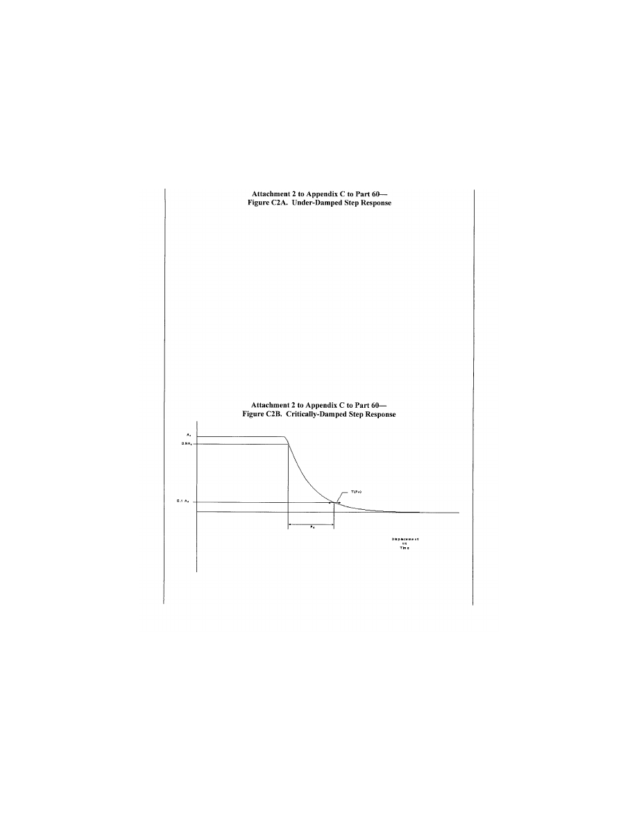
328
14 CFR Ch. I (1–1–24 Edition)
Pt. 60, App. C
E
ND
I
NFORMATION
llllllllllllllllllllllll
5. [R
ESERVED
]
llllllllllllllllllllllll
B
EGIN
I
NFORMATION
6. M
OTION
S
YSTEM
.
a. General.
(1) Pilots use continuous information sig-
nals to regulate the state of the helicopter.
In concert with the instruments and outside-
world visual information, whole-body motion
feedback is essential in assisting the pilot to
VerDate Sep<11>2014
14:00 Mar 14, 2024
Jkt 262047
PO 00000
Frm 00338
Fmt 8010
Sfmt 8002
Q:\14\14V2.TXT
PC31
ER09MY08.034</GPH>
aworley on LAPBH6H6L3 with DISTILLER

329
Federal Aviation Administration, DOT
Pt. 60, App. C
control the helicopter dynamics, particu-
larly in the presence of external disturb-
ances. The motion system should meet basic
objective performance criteria, and be sub-
jectively tuned at the pilot’s seat position to
represent the linear and angular accelera-
tions of the helicopter during a prescribed
minimum set of maneuvers and conditions.
The response of the motion cueing system
should be repeatable.
(2) The Motion System tests in Section 3 of
Table C2A are intended to qualify the FFS
motion cueing system from a mechanical
performance standpoint. Additionally, the
list of motion effects provides a representa-
tive sample of dynamic conditions that
should be present in the flight simulator. An
additional list of representative, training-
critical maneuvers, selected from Section 1,
(Performance tests) and Section 2, (Handling
Qualities tests) in Table C2A, that should be
recorded during initial qualification (but
without tolerance) to indicate the flight sim-
ulator motion cueing performance signature
have been identified (reference Section 3.e).
These tests are intended to help improve the
overall standard of FFS motion cueing.
b. Motion System Checks. The intent of
test 3a, Frequency Response, test 3b, Leg
Balance, and test 3c, Turn-Around Check, as
described in the Table of Objective Tests, is
to demonstrate the performance of the mo-
tion system hardware, and to check the in-
tegrity of the motion set-up with regard to
calibration and wear. These tests are inde-
pendent of the motion cueing software and
should be considered robotic tests.
c. Motion System Repeatability. The in-
tent of this test is to ensure that the motion
system software and motion system hard-
ware have not degraded or changed over
time. This diagnostic test should be com-
pleted during continuing qualification
checks in lieu of the robotic tests. This will
allow an improved ability to determine
changes in the software or determine deg-
radation in the hardware. The following in-
formation delineates the methodology that
should be used for this test.
(1) Input: The inputs should be such that
rotational accelerations, rotational rates,
and linear accelerations are inserted before
the transfer from helicopter center of grav-
ity to pilot reference point with a minimum
amplitude of 5 deg/sec/sec, 10 deg/sec and 0.3
g, respectively, to provide adequate analysis
of the output.
(2) Recommended output:
(a) Actual platform linear accelerations;
the output will comprise accelerations due
to both the linear and rotational motion ac-
celeration;
(b) Motion actuators position.
d. Motion Cueing Performance Signature.
(1) Background. The intent of this test is
to provide quantitative time history records
of motion system response to a selected set
of automated QTG maneuvers during initial
qualification. It is not intended to be a com-
parison of the motion platform accelerations
against the flight test recorded accelerations
(i.e., not to be compared against helicopter
cueing). If there is a modification to the ini-
tially qualified motion software or motion
hardware (e.g., motion washout filter, simu-
lator payload change greater than 10%) then
a new baseline may need to be established.
(2) Test Selection. The conditions identi-
fied in Section 3.e. in Table C2A are those
maneuvers where motion cueing is the most
discernible. They are general tests applicable
to all types of helicopters and should be com-
pleted for motion cueing performance signa-
ture at any time acceptable to the respon-
sible Flight Standards office prior to or dur-
ing the initial qualification evaluation, and
the results included in the MQTG.
(3) Priority. Motion system should be de-
signed with the intent of placing greater im-
portance on those maneuvers that directly
influence pilot perception and control of the
helicopter motions. For the maneuvers iden-
tified in section 3.e. in Table C2A, the flight
simulator motion cueing system should have
a high tilt co-ordination gain, high rota-
tional gain, and high correlation with re-
spect to the helicopter simulation model.
(4) Data Recording. The minimum list of
parameters provided should allow for the de-
termination of the flight simulator’s motion
cueing performance signature for the initial
qualification evaluation. The following pa-
rameters are recommended as being accept-
able to perform such a function:
(a) Flight model acceleration and rota-
tional rate commands at the pilot reference
point;
(b) Motion actuators position;
(c) Actual platform position;
(d) Actual platform acceleration at pilot
reference point.
e. Motion Vibrations.
(1) Presentation of results. The char-
acteristic motion vibrations may be used to
verify that the flight simulator can repro-
duce the frequency content of the helicopter
when flown in specific conditions. The test
results should be presented as a Power Spec-
tral Density (PSD) plot with frequencies on
the horizontal axis and amplitude on the
vertical axis. The helicopter data and flight
simulator data should be presented in the
same format with the same scaling. The al-
gorithms used for generating the flight simu-
lator data should be the same as those used
for the helicopter data. If they are not the
same then the algorithms used for the flight
simulator data should be proven to be suffi-
ciently comparable. As a minimum the re-
sults along the dominant axes should be pre-
sented and a rationale for not presenting the
other axes should be provided.
(2) Interpretation of results. The overall
trend of the PSD plot should be considered
VerDate Sep<11>2014
14:00 Mar 14, 2024
Jkt 262047
PO 00000
Frm 00339
Fmt 8010
Sfmt 8002
Q:\14\14V2.TXT
PC31
aworley on LAPBH6H6L3 with DISTILLER

330
14 CFR Ch. I (1–1–24 Edition)
Pt. 60, App. C
while focusing on the dominant frequencies.
Less emphasis should be placed on the dif-
ferences at the high frequency and low am-
plitude portions of the PSD plot. During the
analysis, certain structural components of
the flight simulator have resonant fre-
quencies that are filtered and may not ap-
pear in the PSD plot. If filtering is required,
the notch filter bandwidth should be limited
to 1 Hz to ensure that the buffet feel is not
adversely affected. In addition, a rationale
should be provided to explain that the char-
acteristic motion vibration is not being ad-
versely affected by the filtering. The ampli-
tude should match helicopter data as de-
scribed below. However, if the PSD plot was
altered for subjective reasons, a rationale
should be provided to justify the change. If
the plot is on a logarithmic scale it may be
difficult to interpret the amplitude of the
buffet in terms of acceleration. For example,
a 1
×
10
¥
3
g-rms
2
/Hz would describe a heavy
buffet and may be seen in the deep stall re-
gime. Alternatively, a 1
×
10
¥
6
g-rms
2
/Hz buf-
fet is almost imperceptable, but may rep-
resent a flap buffet at low speed. The pre-
vious two examples differ in magnitude by
1000. On a PSD plot this represents three dec-
ades (one decade is a change in order of mag-
nitude of 10, and two decades is a change in
order of magnitude of 100).
N
OTE
: In the example, ‘‘g-rms
2
’’ is the
mathematical expression for ‘‘g’s root mean
squared.’’
f. Table C2B, Motion System Recommenda-
tions for Level C and Level D Helicopter
Simulators, contains a description of the pa-
rameters that should be present in simulator
motion systems to provide adequate onset
motion cues to helicopter pilots. The infor-
mation provided covers the six axes of mo-
tion (pitch, roll, yaw, vertical, lateral, and
longitudinal) and addresses displacement,
velocity, and acceleration. Also included is
information about the parameters for initial
rotational and linear acceleration. The pa-
rameters listed in this table apply only to
Level C and Level D simulators, and are pre-
sented here as recommended targets for mo-
tion system capability. They are not require-
ments.
T
ABLE
C2B—M
OTION
S
YSTEM
R
ECOMMENDATIONS FOR
L
EVEL
C
AND
L
EVEL
D H
ELICOPTER
S
IMULATORS
a. ...........
Motion System Envelope
a.1. ........
Pitch
a.1.a. .....
Displacement ......................................................................
±
25
°
a.1.b. .....
Velocity ...............................................................................
±
20
°
/sec
a.1.c. .....
Acceleration ........................................................................
±
100
°
/sec
2
a.2. ........
Roll
a.2.a. .....
Displacement ......................................................................
±
25
°
a.2.b. .....
Velocity ...............................................................................
±
20
°
/sec
a.2.c. .....
Acceleration ........................................................................
±
100
°
/sec
2
a.3. ........
Yaw
a.3.a. .....
Displacement ......................................................................
±
25
°
a.3.b. .....
Velocity— ............................................................................
±
20
°
/sec
a.3.c. .....
Acceleration ........................................................................
±
100
°
/sec
2
a.4. ........
Vertical
a.4.a. .....
Displacement ......................................................................
±
34 in.
a.4.b. .....
Velocity ...............................................................................
±
24 in.
a.4.c. .....
Acceleration ........................................................................
±
0.8 g.
a.5. ........
Lateral
a.5.a. .....
Displacement ......................................................................
±
45 in.
a.5.b. .....
Velocity ...............................................................................
±
28 in/sec.
a.5.c. .....
Acceleration ........................................................................
±
0.6 g.
a.6. ........
Longitudinal
a.6.a. .....
Displacement ......................................................................
±
34 in.
a.6.b. .....
Velocity ...............................................................................
±
28 in/sec.
a.6.c. .....
Acceleration ........................................................................
±
0.6 g.
a.7. ........
Initial Rotational Acceleration Ratio.
All axes 300
°
/ sec
2
/sec
a.8. ........
Initial Linear Acceleration Ratio.
a.8.a. .....
Vertical ................................................................................
±
6g/sec
a.8.b. .....
Lateral .................................................................................
±
3g/sec
a.8.c. .....
Longitudinal .........................................................................
±
3g/sec
VerDate Sep<11>2014
14:00 Mar 14, 2024
Jkt 262047
PO 00000
Frm 00340
Fmt 8010
Sfmt 8006
Q:\14\14V2.TXT
PC31
aworley on LAPBH6H6L3 with DISTILLER
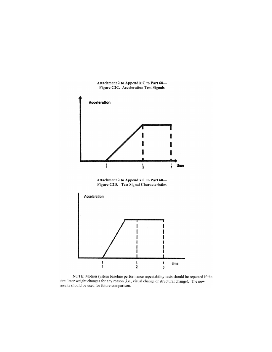
331
Federal Aviation Administration, DOT
Pt. 60, App. C
7. S
OUND
S
YSTEM
a. General. The total sound environment in
the helicopter is very complex, and changes
with atmospheric conditions, helicopter con-
figuration, airspeed, altitude, and power set-
tings. Flight deck sounds are an important
component of the flight deck operational en-
vironment and provide valuable information
VerDate Sep<11>2014
14:00 Mar 14, 2024
Jkt 262047
PO 00000
Frm 00341
Fmt 8010
Sfmt 8002
Q:\14\14V2.TXT
PC31
ER09MY08.035</GPH>
aworley on LAPBH6H6L3 with DISTILLER

332
14 CFR Ch. I (1–1–24 Edition)
Pt. 60, App. C
to the flight crew. These aural cues can ei-
ther assist the crew (as an indication of an
abnormal situation), or hinder the crew (as a
distraction or nuisance). For effective train-
ing, the flight simulator should provide
flight deck sounds that are perceptible to the
pilot during normal and abnormal oper-
ations, and that are comparable to those of
the helicopter. The flight simulator operator
should carefully evaluate background noises
in the location where the device will be in-
stalled. To demonstrate compliance with the
sound requirements, the objective or valida-
tion tests in this attachment were selected
to provide a representative sample of normal
static conditions typically experienced by a
pilot.
b. Alternate propulsion. For FFS with
multiple propulsion configurations, any con-
dition listed in Table C2A in this attachment
should be presented for evaluation as part of
the QTG if identified by the helicopter man-
ufacturer or other data supplier as signifi-
cantly different due to a change in propul-
sion system (engine or propeller).
c. Data and Data Collection System.
(1) Information provided to the flight simu-
lator manufacturer should comply be pre-
sented in the format suggested by the
‘‘International Air Transport Association
(IATA) Flight Simulator Design and Per-
formance Data Requirements,’’ as amended.
This information should contain calibration
and frequency response data.
(2) The system used to perform the tests
listed in Table C2A should comply with the
following standards:
(a) The specifications for octave, half oc-
tave, and third octave band filter sets may
be found in American National Standards In-
stitute (ANSI) S1.11–1986.
(b) Measurement microphones should be
type WS2 or better, as described in Inter-
national Electrotechnical Commission (IEC)
1094–4–1995.
(3) Headsets. If headsets are used during
normal operation of the helicopter they
should also be used during the flight simu-
lator evaluation.
(4) Playback equipment. Playback equip-
ment and recordings of the QTG conditions
should be provided during initial evalua-
tions.
(5) Background noise.
(a) Background noise is the noise in the
flight simulator that is not associated with
the helicopter, but is caused by the flight
simulator’s cooling and hydraulic systems
and extraneous noise from other locations in
the building. Background noise can seriously
impact the correct simulation of helicopter
sounds, and should be kept below the heli-
copter sounds. In some cases, the sound level
of the simulation can be increased to com-
pensate for the background noise. However,
this approach is limited by the specified tol-
erances and by the subjective acceptability
of the sound environment to the evaluation
pilot.
(b) The acceptability of the background
noise levels is dependent upon the normal
sound levels in the helicopter being rep-
resented. Background noise levels that fall
below the lines defined by the following
points, may be acceptable:
(i) 70 dB @ 50 Hz;
(ii) 55 dB @ 1000 Hz;
(iii) 30 dB @ 16 kHz.
(N
OTE
: These limits are for unweighted
1
⁄
3
octave band sound levels. Meeting these lim-
its for background noise does not ensure an
acceptable flight simulator. Helicopter
sounds that fall below this limit require
careful review and may require lower limits
on background noise.)
(6) Validation testing. Deficiencies in heli-
copter recordings should be considered when
applying the specified tolerances to ensure
that the simulation is representative of the
helicopter. Examples of typical deficiencies
are:
(a) Variation of data between tail numbers.
(b) Frequency response of microphones.
(c) Repeatability of the measurements.
T
ABLE
C2C—E
XAMPLE OF
C
ONTINUING
Q
UALI
-
FICATION
F
REQUENCY
R
ESPONSE
T
EST
T
OL
-
ERANCE
Band center
frequency
Initial results
(DbsPL)
Continuing
qualification
results
(DbsPL)
Absolute
difference
50 .....................
75.0 73.8 1.2
63 .....................
75.9 75.6 0.3
80 .....................
77.1 76.5 0.6
100 ...................
78.0 78.3 0.3
125 ...................
81.9 81.3 0.6
160 ...................
79.8 80.1 0.3
200 ...................
83.1 84.9 1.8
250 ...................
78.6 78.9 0.3
315 ...................
79.5 78.3 1.2
400 ...................
80.1 79.5 0.9
500 ...................
80.7 79.8 0.9
630 ...................
81.9 80.4 1.5
800 ...................
73.2 74.1 0.9
1000 .................
79.2 80.1 0.9
1250 .................
80.7 82.8 2.1
1600 .................
81.6 78.6 3.0
2000 .................
76.2 74.4 1.8
2500 .................
79.5 80.7 1.2
3150 .................
80.1 77.1 3.0
4000 .................
78.9 78.6 0.3
5000 .................
80.1 77.1 3.0
6300 .................
80.7 80.4 0.3
8000 .................
84.3 85.5 1.2
10000 ...............
81.3 79.8 1.5
12500 ...............
80.7 80.1 0.6
16000 ...............
71.1 71.1 0.0
Average 1.1
VerDate Sep<11>2014
14:00 Mar 14, 2024
Jkt 262047
PO 00000
Frm 00342
Fmt 8010
Sfmt 8002
Q:\14\14V2.TXT
PC31
aworley on LAPBH6H6L3 with DISTILLER

333
Federal Aviation Administration, DOT
Pt. 60, App. C
8. A
DDITIONAL
I
NFORMATION
A
BOUT
F
LIGHT
S
IMULATOR
Q
UALIFICATION FOR
N
EW OR
D
E
-
RIVATIVE
H
ELICOPTERS
a. Typically, a helicopter manufacturer’s
approved final data for performance, han-
dling qualities, systems or avionics is not
available until well after a new or derivative
helicopter has entered service. However,
flight crew training and certification often
begins several months prior to the entry of
the first helicopter into service. Con-
sequently, it may be necessary to use pre-
liminary data provided by the helicopter
manufacturer for interim qualification of
flight simulators.
b. In these cases, the responsible Flight
Standards office may accept certain par-
tially validated preliminary helicopter and
systems data, and early release (‘‘red label’’)
avionics data in order to permit the nec-
essary program schedule for training, certifi-
cation, and service introduction.
c. Simulator sponsors seeking qualifica-
tion based on preliminary data should con-
sult the responsible Flight Standards office
to make special arrangements for using pre-
liminary data for flight simulator qualifica-
tion. The sponsor should also consult the
helicopter and flight simulator manufactur-
ers to develop a data plan and flight simu-
lator qualification plan.
d. The procedure to be followed to gain the
responsible Flight Standards office accept-
ance of preliminary data will vary from case
to case and between helicopter manufactur-
ers. Each helicopter manufacturer’s new hel-
icopter development and test program is de-
signed to suit the needs of the particular
project and may not contain the same events
or sequence of events asanother manufactur-
er’s program or even the same manufactur-
er’s program for a different helicopter.
Therefore, there cannot be a prescribed in-
variable procedure for acceptance of prelimi-
nary data; instead there should be a state-
ment describing the final sequence of events,
data sources, and validation procedures
agreed by the simulator sponsor, the heli-
copter manufacturer, the flight simulator
manufacturer, and the responsible Flight
Standards office.
N
OTE
: A description of helicopter manufac-
turer-provided data needed for flight simu-
lator modeling and validation is to be found
in the ‘‘Royal Aeronautical Society Data
Package Requirements for Design and Per-
formance Evaluation of Rotary Wing Syn-
thetic Training Devices.’’
e. The preliminary data should be the man-
ufacturer’s best representation of the heli-
copter, with assurance that the final data
will not deviate significantly from the pre-
liminary estimates. Data derived from these
predictive or preliminary techniques should
be validated by available sources including,
at least, the following:
(1) Manufacturer’s engineering report. The
report should explain the predictive method
used and illustrate past success of the meth-
od on similar projects. For example, the
manufacturer could show the application of
the method to an earlier helicopter model or
predict the characteristics of an earlier
model and compare the results to final data
for that model.
(2) Early flight test results. This data is
often derived from helicopter certification
tests and should be used to maximum advan-
tage for early flight simulator validation.
Certain critical tests that would normally be
done early in the helicopter certification
program should be included to validate es-
sential pilot training and certification ma-
neuvers. These tests include cases where a
pilot is expected to cope with a helicopter
failure mode or an engine failure. The early
data available will depend on the helicopter
manufacturer’s flight test program design
and may not be the same in each case. The
flight test program of the helicopter manu-
facturer should include provisions for gen-
eration of very early flight tests results for
flight simulator validation.
f. The use of preliminary data is not indefi-
nite. The helicopter manufacturer’s final
data should be available within 12 months
after the helicopter first entry into service
or as agreed by the responsible Flight Stand-
ards office, the simulator sponsor, and the
helicopter manufacturer. When applying for
interim qualification using preliminary
data, the simulator sponsor and the respon-
sible Flight Standards office should agree on
the update program. This includes specifying
that the final data update will be installed in
the flight simulator within a period of 12
months following the final data release, un-
less special conditions exist and a different
schedule is acceptable. The flight simulator
performance and handling validation would
then be based on data derived from flight
tests. Initial helicopter systems data should
be updated after engineering tests. Final hel-
icopter systems data should also be used for
flight simulator programming and valida-
tion.
g. Flight simulator avionics should stay
essentially in step with helicopter avionics
(hardware and software) updates. The per-
mitted time lapse between helicopter and
flight simulator updates should be minimal.
It may depend on the magnitude of the up-
date and whether the QTG and pilot training
and certification are affected. Differences in
helicopter and flight simulator avionics
versions and the resulting effects on flight
simulator qualification should be agreed be-
tween the simulator sponsor and the respon-
sible Flight Standards office. Consultation
with the flight simulator manufacturer is de-
sirable throughout the qualification process.
h. The following describes an example of
the design data and sources that might be
VerDate Sep<11>2014
14:00 Mar 14, 2024
Jkt 262047
PO 00000
Frm 00343
Fmt 8010
Sfmt 8002
Q:\14\14V2.TXT
PC31
aworley on LAPBH6H6L3 with DISTILLER

334
14 CFR Ch. I (1–1–24 Edition)
Pt. 60, App. C
used in the development of an interim quali-
fication plan.
(1) The plan should consist of the develop-
ment of a QTG based upon a mix of flight
test and engineering simulation data. For
data collected from specific helicopter flight
tests or other flights the required design
model or data changes necessary to support
an acceptable Proof of Match (POM) should
be generated by the helicopter manufacturer.
(2) For proper validation of the two sets of
data, the helicopter manufacturer should
compare their simulation model responses
against the flight test data, when driven by
the same control inputs and subjected to the
same atmospheric conditions as recorded in
the flight test. The model responses should
result from a simulation where the following
systems are run in an integrated fashion and
are consistent with the design data released
to the flight simulator manufacturer:
(a) Propulsion.
(b) Aerodynamics.
(c) Mass properties.
(d) Flight controls.
(e) Stability augmentation.
(f) Brakes/landing gear.
i. A qualified test pilot should be used to
assess handling qualities and performance
evaluations for the qualification of flight
simulators of new helicopter types.
E
ND
I
NFORMATION
llllllllllllllllllllllll
B
EGIN
QPS R
EQUIREMENT
9. E
NGINEERING
S
IMULATOR
—V
ALIDATION
D
ATA
a. When a fully validated simulation (i.e.,
validated with flight test results) is modified
due to changes to the simulated helicopter
configuration, the helicopter manufacturer
or other acceptable data supplier must co-
ordinate with the responsible Flight Stand-
ards office to supply validation data from an
‘‘audited’’ engineering simulator/simulation
to selectively supplement flight test data.
The responsible Flight Standards office must
be provided an opportunity to audit the use
of the engineering simulation or the engi-
neering simulator during the acquisition of
the data that will be used as validation data.
Audited data may be used for changes that
are incremental in nature. Manufacturers or
other data suppliers must be able to dem-
onstrate that the predicted changes in heli-
copter performance are based on acceptable
aeronautical principles with proven success
history and valid outcomes. This must in-
clude comparisons of predicted and flight
test validated data.
b. Helicopter manufacturers or other ac-
ceptable data suppliers seeking to use an en-
gineering simulator for simulation valida-
tion data as an alternative to flight-test de-
rived validation data, must contact the re-
sponsible Flight Standards office and provide
the following:
(1) A description of the proposed aircraft
changes, a description of the proposed sim-
ulation model changes, and the use of an in-
tegral configuration management process,
including an audit of the actual simulation
model modifications that includes a step-by-
step description leading from the original
model(s) to the current model(s).
(2) A schedule for review by the responsible
Flight Standards office of the proposed plan
and the subsequent validation data to estab-
lish acceptability of the proposal.
(3) Validation data from an audited engi-
neering simulator/simulation to supplement
specific segments of the flight test data.
c. To be qualified to supply engineering
simulator validation data, for aerodynamic,
engine, flight control, or ground handling
models, a helicopter manufacturer or other
acceptable data supplier must:
(1) Be able to verify their ability to:
(a) Develop and implement high fidelity
simulation models; and
(b) Predict the handling and performance
characteristics of a helicopter with suffi-
cient accuracy to avoid additional flight test
activities for those handling and perform-
ance characteristics.
(2) Have an engineering simulator that:
(a) Is a physical entity, complete with a
flight deck representative of the simulated
class of helicopter;
(b) Has controls sufficient for manual
flight;
(c) Has models that run in an integrated
manner;
(d) Had fully flight-test validated simula-
tion models as the original or baseline sim-
ulation models;
(e) Has an out-of-the-flight deck visual sys-
tem;
(f) Has actual avionics boxes interchange-
able with the equivalent software simula-
tions to support validation of released soft-
ware;
(g) Uses the same models as released to the
training community (which are also used to
produce stand-alone proof-of-match and
checkout documents);
(h) Is used to support helicopter develop-
ment and certification; and
(i) Has been found to be a high fidelity rep-
resentation of the helicopter by the manu-
facturer’s pilots (or other acceptable data
supplier), certificate holders, and the respon-
sible Flight Standards office.
(3) Use the engineering simulator to
produce a representative set of integrated
proof-of-match cases.
(4) Use a configuration control system cov-
ering hardware and software for the oper-
ating components of the engineering simu-
lator.
(5) Demonstrate that the predicted effects
of the change(s) are within the provisions of
VerDate Sep<11>2014
14:00 Mar 14, 2024
Jkt 262047
PO 00000
Frm 00344
Fmt 8010
Sfmt 8002
Q:\14\14V2.TXT
PC31
aworley on LAPBH6H6L3 with DISTILLER

335
Federal Aviation Administration, DOT
Pt. 60, App. C
sub-paragraph ‘‘a’’ of this section, and con-
firm that additional flight test data are not
required.
d. Additional Requirements for Validation
Data
(1) When used to provide validation data,
an engineering simulator must meet the sim-
ulator standards currently applicable to
training simulators except for the data pack-
age.
(2) The data package used must be:
(a) Comprised of the engineering pre-
dictions derived from the helicopter design,
development, or certification process;
(b) Based on acceptable aeronautical prin-
ciples with proven success history and valid
outcomes for aerodynamics, engine oper-
ations, avionics operations, flight control ap-
plications, or ground handling;
(c) Verified with existing flight-test data;
and
(d) Applicable to the configuration of a
production helicopter, as opposed to a flight-
test helicopter.
(3) Where engineering simulator data are
used as part of a QTG, an essential match
must exist between the training simulator
and the validation data.
(4) Training flight simulator(s) using these
baseline and modified simulation models
must be qualified to at least internationally
recognized standards, such as contained in
the ICAO Document 9625, the ‘‘Manual of Cri-
teria for the Qualification of Flight Simula-
tors.’’
E
ND
QPS R
EQUIREMENT
llllllllllllllllllllllll
10. [R
ESERVED
]
11. V
ALIDATION
T
EST
T
OLERANCES
llllllllllllllllllllllll
B
EGIN
I
NFORMATION
a. Non-Flight-Test Tolerances. If engineer-
ing simulator data or other non-flight-test
data are used as an allowable form of ref-
erence validation data for the objective tests
listed in Table C2A of this attachment, the
data provider must supply a well-docu-
mented mathematical model and testing pro-
cedure that enables a replication of the engi-
neering simulation results within 20% of the
corresponding flight test tolerances.
b. Background
(1) The tolerances listed in Table C2A of
this attachment are designed to measure the
quality of the match using flight-test data as
a reference.
(2) Good engineering judgment should be
applied to all tolerances in any test. A test
is failed when the results fall outside of the
prescribed tolerance(s).
(3) Engineering simulator data are accept-
able because the same simulation models
used to produce the reference data are also
used to test the flight training simulator
(i.e., the two sets of results should be ‘‘es-
sentially’’ similar).
(4) The results from the two sources may
differ for the following reasons:
(a) Hardware (avionics units and flight
controls);
(b) Iteration rates;
(c) Execution order;
(d) Integration methods;
(e) Processor architecture;
(f) Digital drift, including:
(i) Interpolation methods;
(ii) Data handling differences;
(iii) Auto-test trim tolerances.
(5) The tolerance limit between the ref-
erence data and the flight simulator results
is generally 20% of the corresponding
‘‘flight-test’’ tolerances. However, there may
be cases where the simulator models used are
of higher fidelity, or the manner in which
they are cascaded in the integrated testing
loop have the effect of a higher fidelity, than
those supplied by the data provider. Under
these circumstances, it is possible that an
error greater than 20% may be generated. An
error greater than 20% may be acceptable if
the simulator sponsor can provide an ade-
quate explanation.
(6) Guidelines are needed for the applica-
tion of tolerances to engineering-simulator-
generated validation data because:
(a) Flight-test data are often not available
due to sound technical reasons;
(b) Alternative technical solutions are
being advanced; and
(c) The costs are high.
12. V
ALIDATION
D
ATA
R
OADMAP
a. Helicopter manufacturers or other data
suppliers should supply a validation data
roadmap (VDR) document as part of the data
package. A VDR document contains guid-
ance material from the helicopter validation
data supplier recommending the best pos-
sible sources of data to be used as validation
data in the QTG. A VDR is of special value
when requesting interim qualification, quali-
fication of simulators for helicopters certifi-
cated prior to 1992, and qualification of alter-
nate engine or avionics fits. A sponsor seek-
ing to have a device qualified in accordance
with the standards contained in this QPS ap-
pendix should submit a VDR to the respon-
sible Flight Standards office as early as pos-
sible in the planning stages. The NSPM is
the final authority to approve the data to be
used as validation material for the QTG. The
responsible Flight Standards office and the
Joint Aviation Authorities’ Synthetic Train-
ing Devices Advisory Board have committed
to maintain a list of agreed VDRs.
b. The VDR should identify (in matrix for-
mat) sources of data for all required tests. It
should also provide guidance regarding the
validity of these data for a specific engine
VerDate Sep<11>2014
14:00 Mar 14, 2024
Jkt 262047
PO 00000
Frm 00345
Fmt 8010
Sfmt 8002
Q:\14\14V2.TXT
PC31
aworley on LAPBH6H6L3 with DISTILLER

336
14 CFR Ch. I (1–1–24 Edition)
Pt. 60, App. C
type, thrust rating configuration, and the re-
vision levels of all avionics affecting heli-
copter handling qualities and performance.
The VDR should include rationale or expla-
nation in cases where data or parameters are
missing, engineering simulation data are to
be used, flight test methods require expla-
nation, or where there is any deviation from
data requirements. Additionally, the docu-
ment should refer to other appropriate
sources of validation data (e.g., sound and vi-
bration data documents).
c. The Sample Validation Data Roadmap
(VDR) for helicopters, shown in Table C2D,
depicts a generic roadmap matrix identifying
sources of validation data for an abbreviated
list of tests. This sample document uses
fixed wing parameters instead of helicopter
values. It is merely a sample and does not
provide actual data. A complete matrix
should address all test conditions for heli-
copter application and provide actual data
and data sources.
d. Two examples of rationale pages are pre-
sented in Appendix F of IATA Flight Simu-
lator Design and Performance Data Require-
ments document. These illustrate the type of
helicopter and avionics configuration infor-
mation and descriptive engineering rationale
used to describe data anomalies or provide
an acceptable basis for using alternative
data for QTG validation requirements.
E
ND
I
NFORMATION
llllllllllllllllllllllll
VerDate Sep<11>2014
14:00 Mar 14, 2024
Jkt 262047
PO 00000
Frm 00346
Fmt 8010
Sfmt 8002
Q:\14\14V2.TXT
PC31
aworley on LAPBH6H6L3 with DISTILLER
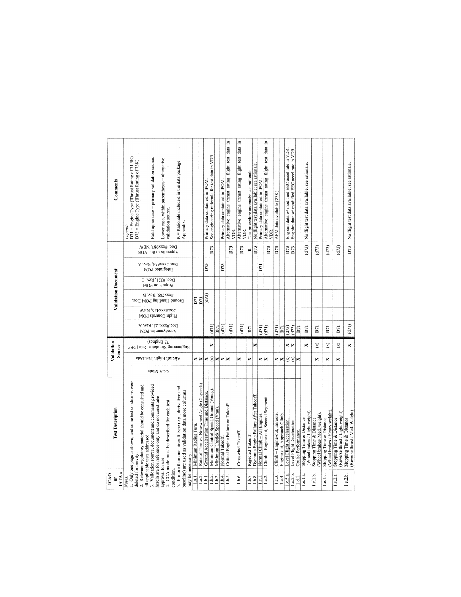
337
Federal Aviation Administration, DOT
Pt. 60, App. C
VerDate Sep<11>2014
14:00 Mar 14, 2024
Jkt 262047
PO 00000
Frm 00347
Fmt 8010
Sfmt 8006
Q:\14\14V2.TXT
PC31
ER09MY08.036</GPH>
aworley on LAPBH6H6L3 with DISTILLER

338
14 CFR Ch. I (1–1–24 Edition)
Pt. 60, App. C
B
EGIN
I
NFORMATION
llllllllllllllllllllllll
13. [R
ESERVED
]
14. A
CCEPTANCE
G
UIDELINES FOR
A
LTERNATIVE
A
VIONICS
(F
LIGHT
-R
ELATED
C
OMPUTERS AND
C
ONTROLLERS
)
a. Background
(1) For a new helicopter type, the majority
of flight validation data are collected on the
first helicopter configuration with a ‘‘base-
line’’ flight-related avionics ship-set; (see
subparagraph b.(2) of this section). These
data are then used to validate all flight sim-
ulators representing that helicopter type.
(2) Additional validation data may be need-
ed for flight simulators representing a heli-
copter with avionics of a different hardware
design than the baseline, or a different soft-
ware revision than that of previously vali-
dated configurations.
(3) When a flight simulator with additional
or alternate avionics configurations is to be
qualified, the QTG should contain tests
against validation data for selected cases
where avionics differences are expected to be
significant.
b. Approval Guidelines For Validating
Alternate Avionics
(1) The following guidelines apply to flight
simulators representing helicopters with a
revised avionics configuration, or more than
one avionics configuration.
(2) The baseline validation data should be
based on flight test data, except where other
data are specifically allowed (e.g., engineer-
ing flight simulator data).
(3) The helicopter avionics can be seg-
mented into two groups, systems or compo-
nents whose functional behavior contributes
to the aircraft response presented in the
QTG results, and systems that do not. The
following avionics are examples of contribu-
tory systems for which hardware design
changes or software revisions may lead to
significant differences in the aircraft re-
sponse relative to the baseline avionics con-
figuration: Flight control computers and
controllers for engines, autopilot, braking
system, and nosewheel steering system, if
applicable. Related avionics such as aug-
mentation systems should also be consid-
ered.
(4) The acceptability of validation data
used in the QTG for an alternative avionics
fit should be determined as follows:
(a) For changes to an avionics system or
component that do not affect QTG validation
test response, the QTG test can be based on
validation data from the previously vali-
dated avionics configuration.
(b) For an avionics change to a contribu-
tory system, where a specific test is not af-
fected by the change (e.g., the avionics
change is a Built In Test Equipment (BITE)
update or a modification in a different flight
phase), the QTG test can be based on valida-
tion data from the previously-validated avi-
onics configuration. The QTG should include
authoritative justification (e.g., from the
helicopter manufacturer or system supplier)
that this avionics change does not affect the
test.
(c) For an avionics change to a contribu-
tory system, the QTG may be based on vali-
dation data from the previously-validated
avionics configuration if no new
functionality is added and the impact of the
avionics change on the helicopter response is
based on acceptable aeronautical principles
with proven success history and valid out-
comes. This should be supplemented with
avionics-specific validation data from the
helicopter manufacturer’s engineering sim-
ulation, generated with the revised avionics
configuration. The QTG should include an
explanation of the nature of the change and
its effect on the helicopter response.
(d) For an avionics change to a contribu-
tory system that significantly affects some
tests in the QTG, or where new functionality
is added, the QTG should be based on valida-
tion data from the previously validated avi-
onics configuration and supplemental avi-
onics-specific flight test data sufficient to
validate the alternate avionics revision. Ad-
ditional flight test validation data may not
be needed if the avionics changes were cer-
tified without the need for testing with a
comprehensive flight instrumentation pack-
age. The helicopter manufacturer should co-
ordinate flight simulator data requirements
in advance with the responsible Flight
Standards office.
(5) A matrix or ‘‘roadmap’’ should be pro-
vided with the QTG indicating the appro-
priate validation data source for each test.
The roadmap should include identification of
the revision state of those contributory avi-
onics systems that could affect specific test
responses.
15. T
RANSPORT
D
ELAY
T
ESTING
a. This paragraph describes how to deter-
mine the introduced transport delay through
the flight simulator system so that it does
not exceed a specific time delay. The trans-
port delay should be measured from control
inputs through the interface, through each
of the host computer modules and back
through the interface to motion, flight in-
strument, and visual systems. The transport
delay should not exceed the maximum allow-
able interval.
b. Four specific examples of transport
delay are:
(1) Simulation of classic non-computer
controlled aircraft;
(2) Simulation of Computer Controlled Air-
craft using real helicopter black boxes;
VerDate Sep<11>2014
14:00 Mar 14, 2024
Jkt 262047
PO 00000
Frm 00348
Fmt 8010
Sfmt 8002
Q:\14\14V2.TXT
PC31
aworley on LAPBH6H6L3 with DISTILLER

339
Federal Aviation Administration, DOT
Pt. 60, App. C
(3) Simulation of Computer Controlled Air-
craft using software emulation of helicopter
boxes;
(4) Simulation using software avionics or
rehosted instruments.
c. Figure C2C illustrates the total trans-
port delay for a non-computer-controlled
helicopter or the classic transport delay test.
Since there are no helicopter-induced delays
for this case, the total transport delay is
equivalent to the introduced delay.
d. Figure C2D illustrates the transport
delay testing method using the real heli-
copter controller system.
e. To obtain the induced transport delay
for the motion, instrument and visual signal,
the delay induced by the helicopter con-
troller should be subtracted from the total
transport delay. This difference represents
the introduced delay and should not exceed
the standards prescribed in Table C1A.
f. Introduced transport delay is measured
from the flight deck control input to the re-
action of the instruments and motion and
visual systems (See Figure C2C).
g. The control input may also be intro-
duced after the helicopter controller system
input and the introduced transport delay
may be measured directly from the control
input to the reaction of the instruments, and
simulator motion and visual systems (See
Figure C2D).
h. Figure C2E illustrates the transport
delay testing method used on a flight simu-
lator that uses a software emulated heli-
copter controller system.
i. It is not possible to measure the intro-
duced transport delay using the simulated
helicopter controller system architecture for
the pitch, roll and yaw axes. Therefore, the
signal should be measured directly from the
pilot controller. The flight simulator manu-
facturer should measure the total transport
delay and subtract the inherent delay of the
actual helicopter components because the
real helicopter controller system has an in-
herent delay provided by the helicopter man-
ufacturer. The flight simulator manufac-
turer should ensure that the introduced
delay does not exceed the standards pre-
scribed in Table C1A.
j. Special measurements for instrument
signals for flight simulators using a real hel-
icopter instrument display system instead of
a simulated or re-hosted display. For flight
instrument systems, the total transport
delay should be measured and the inherent
delay of the actual helicopter components
subtracted to ensure that the introduced
delay does not exceed the standards pre-
scribed in Table C1A.
(1) Figure C2FA illustrates the transport
delay procedure without helicopter display
simulation. The introduced delay consists of
the delay between the control movement and
the instrument change on the data bus.
(2) Figure C2FB illustrates the modified
testing method required to measure intro-
duced delay due to software avionics or re-
hosted instruments. The total simulated in-
strument transport delay is measured and
the helicopter delay should be subtracted
from this total. This difference represents
the introduced delay and should not exceed
the standards prescribed in Table C1A. The
inherent delay of the helicopter between the
data bus and the displays is indicated in fig-
ure C2FA. The display manufacturer should
provide this delay time.
k. Recorded signals. The signals recorded
to conduct the transport delay calculations
should be explained on a schematic block
diagram. The flight simulator manufacturer
should also provide an explanation of why
each signal was selected and how they relate
to the above descriptions.
l. Interpretation of results. Flight simu-
lator results vary over time from test to test
due to ‘‘sampling uncertainty.’’ All flight
simulators run at a specific rate where all
modules are executed sequentially in the
host computer. The flight controls input can
occur at any time in the iteration, but these
data will not be processed before the start of
the new iteration. For example, a flight sim-
ulator running at 60 Hz may have a dif-
ference of as much as 16.67 msec between re-
sults. This does not mean that the test has
failed. Instead, the difference is attributed to
variation in input processing. In some condi-
tions, the host simulator and the visual sys-
tem do not run at the same iteration rate, so
the output of the host computer to the visual
system will not always be synchronized.
m. The transport delay test should account
for both daylight and night modes of oper-
ation of the visual system. In both cases, the
tolerances prescribed in Table C1A should be
met and the motion response should occur
before the end of the first video scan con-
taining new information.
VerDate Sep<11>2014
14:00 Mar 14, 2024
Jkt 262047
PO 00000
Frm 00349
Fmt 8010
Sfmt 8002
Q:\14\14V2.TXT
PC31
aworley on LAPBH6H6L3 with DISTILLER
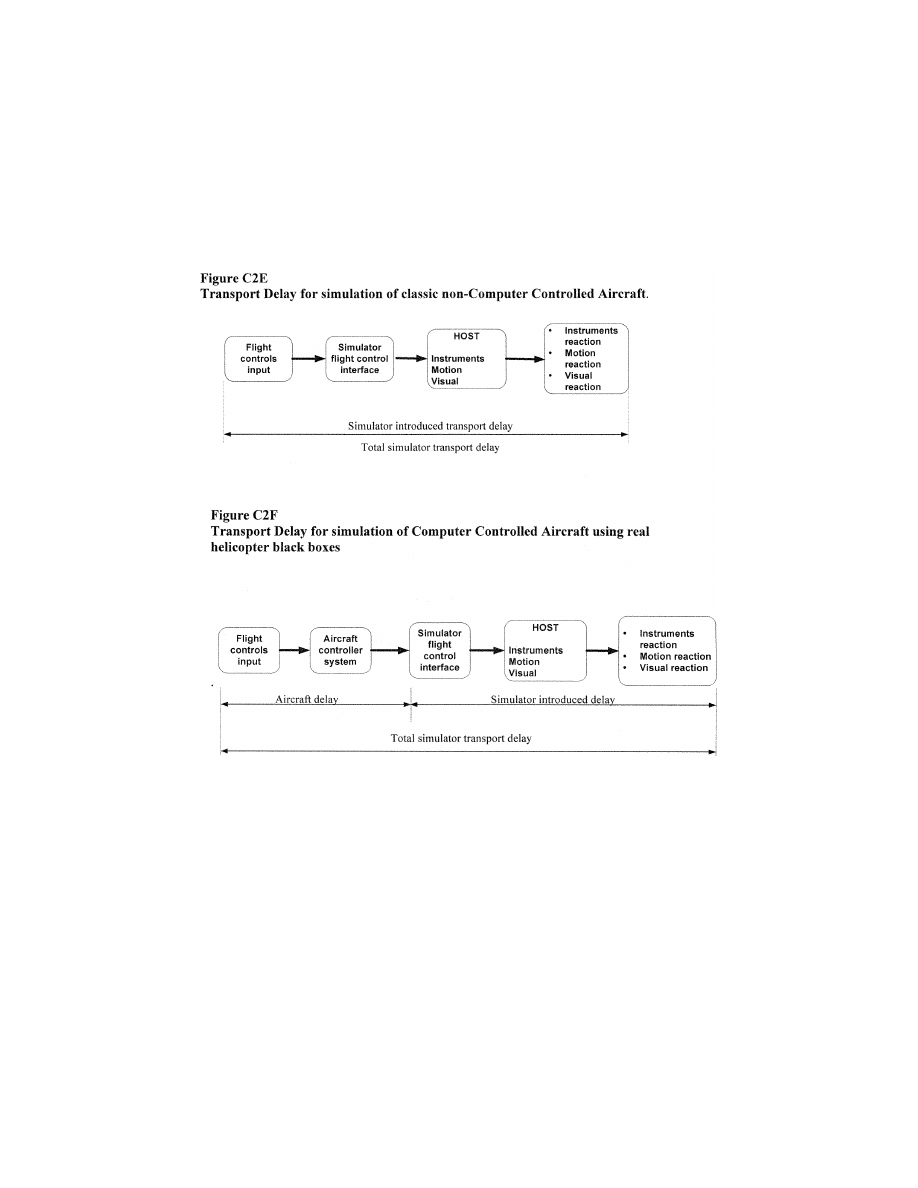
340
14 CFR Ch. I (1–1–24 Edition)
Pt. 60, App. C
VerDate Sep<11>2014
14:00 Mar 14, 2024
Jkt 262047
PO 00000
Frm 00350
Fmt 8010
Sfmt 8006
Q:\14\14V2.TXT
PC31
ER09MY08.037</GPH>
aworley on LAPBH6H6L3 with DISTILLER
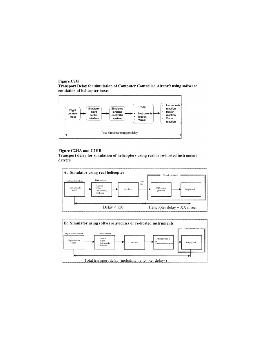
341
Federal Aviation Administration, DOT
Pt. 60, App. C
16. C
ONTINUING
Q
UALIFICATION
E
VALUATIONS
—
V
ALIDATION
T
EST
D
ATA
P
RESENTATION
a. Background
(1) The MQTG is created during the initial
evaluation of a flight simulator. This is the
master document, as amended, to which
flight simulator continuing qualification
evaluation test results are compared.
(2) The currently accepted method of pre-
senting continuing qualification evaluation
test results is to provide flight simulator re-
sults over-plotted with reference data. Test
results are carefully reviewed to determine if
the test is within the specified tolerances.
This can be a time consuming process, par-
ticularly when reference data exhibits rapid
variations or an apparent anomaly requiring
engineering judgment in the application of
VerDate Sep<11>2014
14:00 Mar 14, 2024
Jkt 262047
PO 00000
Frm 00351
Fmt 8010
Sfmt 8002
Q:\14\14V2.TXT
PC31
ER09MY08.038</GPH>
aworley on LAPBH6H6L3 with DISTILLER

342
14 CFR Ch. I (1–1–24 Edition)
Pt. 60, App. C
the tolerances. In these cases, the solution is
to compare the results to the MQTG. The
continuing qualification results are com-
pared to the results in the MQTG for accept-
ance. The flight simulator operator and the
responsible Flight Standards office should
look for any change in the flight simulator
performance since initial qualification.
b. Continuing Qualification Evaluation Test
Results Presentation
(1) Flight simulator operators are encour-
aged to over-plot continuing qualification
validation test results with MQTG flight
simulator results recorded during the initial
evaluation and as amended. Any change in a
validation test will be readily apparent. In
addition to plotting continuing qualification
validation test and MQTG results, operators
may elect to plot reference data.
(2) There are no suggested tolerances be-
tween flight simulator continuing qualifica-
tion and MQTG validation test results. In-
vestigation of any discrepancy between the
MQTG and continuing qualification flight
simulator performance is left to the discre-
tion of the flight simulator operator and the
responsible Flight Standards office.
(3) Differences between the two sets of re-
sults, other than variations attributable to
repeatability issues that cannot be explained
should be investigated.
(4) The flight simulator should retain the
ability to over-plot both automatic and man-
ual validation test results with reference
data.
E
ND
I
NFORMATION
llllllllllllllllllllllll
B
EGIN
QPS R
EQUIREMENTS
17. A
LTERNATIVE
D
ATA
S
OURCES
, P
ROCE
-
DURES
,
AND
I
NSTRUMENTATION
: L
EVEL
B
S
IMULATORS
O
NLY
a. Sponsors are not required to use the al-
ternative data sources, procedures, and in-
strumentation. However, any sponsor choos-
ing to use alternative sources must comply
with the requirements in Table C2E.
E
ND
QPS R
EQUIREMENTS
llllllllllllllllllllllll
B
EGIN
I
NFORMATION
b. It has become standard practice for ex-
perienced simulator manufacturers to use
such techniques as a means of establishing
data bases for new simulator configurations
while awaiting the availability of actual
flight test data. The data generated from the
aerodynamic modeling techniques is then
compared to the flight test data when it be-
comes available. The results of such com-
parisons have become increasingly con-
sistent, indicating that these techniques, ap-
plied with appropriate experience, are de-
pendable and accurate for the development
of aerodynamic models for use in Level B
simulators.
c. Based on this history of successful com-
parisons, the responsible Flight Standards
office has concluded that those who are expe-
rienced in the development of aerodynamic
models for simulator application can suc-
cessfully use these modeling techniques to
alter the method for acquiring flight test
data for Level B simulators.
d. The information in Table C2E (Alter-
native Data Sources, Procedures, and Infor-
mation) is presented to describe an accept-
able alternative to data sources for simu-
lator modeling and validation and an accept-
able alternative to the procedures and in-
strumentation traditionally used to gather
such modeling and validation data.
(1) Alternative data sources that may be
used for part or all of a data requirement are
the Helicopter Maintenance Manual, the
Rotorcraft Flight Manual (RFM), Helicopter
Design Data, the Type Inspection Report
(TIR), Certification Data or acceptable sup-
plemental flight test data.
(2) The sponsor should coordinate with the
responsible Flight Standards office prior to
using alternative data sources in a flight
test or data gathering effort.
e. The responsible Flight Standards office
position on the use of these alternative data
sources, procedures, and instrumentation is
based on the use of a rigorously defined and
fully mature simulation controls system
model that includes accurate gearing and
cable stretch characteristics (where applica-
ble), determined from actual aircraft meas-
urements. The model does not require con-
trol surface position measurements in the
flight test objective data in these limited ap-
plications.
f. Data may be acquired by using an iner-
tial measurement system and a synchronized
video of the calibrated helicopter instru-
ments, including the inclinometer; the force/
position measurements of flight deck con-
trols; and a clear visual directional reference
for a known magnetic bearing (e.g., a runway
centerline). Ground track and wind corrected
heading may be used for sideslip angle.
g. The sponsor is urged to contact the re-
sponsible Flight Standards office for clari-
fication of any issue regarding helicopters
with reversible control systems. This table is
not applicable to Computer Controlled Air-
craft flight simulators.
h. Use of these alternate data sources, pro-
cedures, and instrumentation does not re-
lieve the sponsor from compliance with the
balance of the information contained in this
document relative to Level B FFSs.
i. The term ‘‘inertial measurement sys-
tem’’ is used in table C2E includes the use of
a functional global positioning system
(GPS).
VerDate Sep<11>2014
14:00 Mar 14, 2024
Jkt 262047
PO 00000
Frm 00352
Fmt 8010
Sfmt 8002
Q:\14\14V2.TXT
PC31
aworley on LAPBH6H6L3 with DISTILLER

343
Federal Aviation Administration, DOT
Pt. 60, App. C
j. Synchronized video for the use of alter-
native data sources, procedures, and instru-
mentation should have:
(1) sufficient resolution to allow mag-
nification of the display to make appropriate
measurement and comparisons; and
(2) sufficient size and incremental marking
to allow similar measurement and compari-
son. The detail provided by the video should
provide sufficient clarity and accuracy to
measure the necessary parameter(s) to at
least
1
⁄
2
of the tolerance authorized for the
specific test being conducted and allow an
integration of the parameter(s) in question
to obtain a rate of change.
E
ND
I
NFORMATION
llllllllllllllllllllllll
T
ABLE
C2E—A
LTERNATIVE
D
ATA
S
OURCES
, P
ROCEDURES
,
AND
I
NSTRUMENTATION
[The standards in this table are required if the data gathering methods described in paragraph 9 of Appendix C are not used]
QPS requirements
Information
Table of objective tests
Level
By
only
Alternative data sources, procedures, and instrumentation
Notes
Test entry number and title
1.a.1.a. Performance. En-
gine Start and Accelera-
tions.
X
Data may be acquired using a synchronized video recording of all
engine instruments, start buttons, means for fuel introduction and
means for moving from ‘‘idle’’ to ‘‘flight.’’ A stopwatch is nec-
essary.
1.a.1.b. Performance.
Steady State Idle and
Operating RPM Condi-
tions.
X
Data may be acquired using a synchronized video recording of all
engine instruments, and include the status of the means for mov-
ing from ‘‘idle’’ to ‘‘flight.’’.
1.a.2. Performance. Power
Turbine Speed Trim.
X
Data may be acquired using a synchronized video recording of all
engine instruments. Speed trim actuator position may be hand re-
corded.
1.a.3. Performance. Engine
and Rotor Speed Gov-
erning.
X
Data may be acquired by using a synchronized video of the cali-
brated helicopter instruments and the force/position measure-
ments of flight deck controls.
1.b.1. Performance. On
Surface Taxi. Minimum
Radius Turn.
X
TIR, AFM, or Design data may be used.
1.b.2. Performance. On
Surface Taxi Rate of
Turn vs. Nosewheel
Steering Angle.
X
Data may be acquired by using a constant tiller position (measured
with a protractor), or full pedal application for steady state turn,
and synchronized video of heading indicator. If less than full
pedal is used, pedal position must be recorded..
A single procedure
may not be ade-
quate for all rotor-
craft steering sys-
tems. Appropriate
measurement
procedures must
be devised and
proposed for re-
sponsible Flight
Standards office
concurrence.
1.b.3. Performance. Taxi ...
X
Data may be acquired by using a synchronized video of the cali-
brated helicopter instruments and the force/position measure-
ments of flight deck controls.
1.b.4. Performance. Brake
X
Data may be acquired using a stopwatch and a means for meas-
uring distance such as runway distance markers conforming with
runway distance marker standards.
1.c.1. Performance. Run-
ning Takeoff.
X
Preliminary certification data may be used. Data may be acquired
by using a synchronized video of the calibrated helicopter instru-
ments and the force/position measurements of flight deck con-
trols. Collective, cyclic, and pedal position time history must be
recorded from the start of collective movement through to normal
climb. Indicated torque settings may be hand recorded at the mo-
ment of lift-off and in a steady normal climb.
1.c.2. Performance. One
Engine Inoperative (OEI),
continued takeoff.
X
Data may be acquired by using a synchronized video of the cali-
brated helicopter instruments and the force/position measure-
ments of flight deck controls. Collective, cyclic, and pedal position
time history must be recorded from the start of collective move-
ment through to normal OEI climb. Indicated torque settings may
be hand recorded at the moment of lift-off and in a steady normal
OEI climb.
1.f. Performance. Level
Flight. Trimmed Flight
Control Positions.
X
Data may be acquired by using a synchronized video of the cali-
brated helicopter instruments and the force/position measure-
ments of flight deck controls.
1.g. Performance. Normal
Climb. Trimmed Flight
Control Positions.
X
Data may be acquired by using a synchronized video of the cali-
brated helicopter instruments and the force/position measure-
ments of flight deck controls.
VerDate Sep<11>2014
14:00 Mar 14, 2024
Jkt 262047
PO 00000
Frm 00353
Fmt 8010
Sfmt 8002
Q:\14\14V2.TXT
PC31
aworley on LAPBH6H6L3 with DISTILLER

344
14 CFR Ch. I (1–1–24 Edition)
Pt. 60, App. C
T
ABLE
C2E—A
LTERNATIVE
D
ATA
S
OURCES
, P
ROCEDURES
,
AND
I
NSTRUMENTATION
—Continued
[The standards in this table are required if the data gathering methods described in paragraph 9 of Appendix C are not used]
QPS requirements
Information
Table of objective tests
Level
By
only
Alternative data sources, procedures, and instrumentation
Notes
Test entry number and title
1.h.1. Descent Perform-
ance and Trimmed Flight
Control Positions.
X
Data may be acquired by using a synchronized video of the cali-
brated helicopter instruments and the force/position measure-
ments of flight deck controls.
1.h.2. Autorotation Perform-
ance and Trimmed Flight
Control Positions.
X
Data may be acquired by using a synchronized video of the cali-
brated helicopter instruments and the force/position measure-
ments of flight deck controls.
1.j.1. Performance. Run-
ning Landing All Engines.
X
Data may be acquired by using a synchronized video of the cali-
brated helicopter instruments and the force/position measure-
ments of flight deck controls.
1.j.2. Performance. Run-
ning Landing One Engine
Inoperative.
X
Data may be acquired by using a synchronized video of the cali-
brated helicopter instruments and the force/position measure-
ments of flight deck controls.
1.j.3. Performance. Balked
Landing.
X
Data may be acquired by using a synchronized video of the cali-
brated helicopter instruments and the force/position measure-
ments of flight deck controls. The synchronized video must record
the time of the ‘‘balk landing’’ decision.
2.a.1. Handling Qualities.
Static Control Checks.
Cyclic Controller Position
vs. Force.
X
Control positions can be obtained using continuous control position
recordings. Force data may be acquired by using a hand held
force gauge so that the forces can be cross-plotted against con-
trol position in each of the control axes.
2.a.2. Handling Qualities.
Static Control Checks.
Collective/Pedals vs.
Force.
X
Control positions can be obtained using continuous control position
recordings. Force data may be acquired by using a hand held
force gauge so that the forces can be cross-plotted against con-
trol position in each of the control axes.
2.a.3. Handling Qualities.
Brake Pedal Force vs.
Position.
X
Brake pedal positions can be obtained using continuous position re-
cordings. Force data may be acquired by using a hand held force
gauge so that the forces can be cross-plotted against brake pedal
position.
2.a.4. Handling Qualities.
Trim System Rate (all
applicable systems).
X
Control positions can be obtained using continuous control position
recordings plotted against time to provide rate in each applicable
system.
2.a.6. Handling Qualities.
Control System Freeplay.
X
Data may be acquired by direct measurement.
2.c.1. Longitudinal Handling
Qualities. Control Re-
sponse.
X
Data may be acquired by using an inertial measurement system, a
synchronized video of the calibrated helicopter instruments and
the force/position measurements of flight deck controls.
2.c.2. Longitudinal Handling
Qualities. Static Stability.
X
Data may be acquired by using an inertial measurement system, a
synchronized video of the calibrated helicopter instruments and
the force/position measurements of flight deck controls.
2.c.3.a. Longitudinal Han-
dling Qualities. Dynamic
Stability, Long Term Re-
sponse.
X
Data may be acquired by using an inertial measurement system, a
synchronized video of the calibrated helicopter instruments and
the force/position measurements of flight deck controls.
2.c.3.b. Longitudinal Han-
dling Qualities. Dynamic
Stability, Short Term Re-
sponse.
X
Data may be acquired by using an inertial measurement system, a
synchronized video of the calibrated helicopter instruments and
the force/position measurements of flight deck controls.
2.c.4. Longitudinal Handling
Qualities. Maneuvering
stability.
X
Data may be acquired by using an inertial measurement system, a
synchronized video of the calibrated helicopter instruments and
the force/position measurements of flight deck controls.
2.d.1.a. Lateral Handling
Qualities. Control Re-
sponse.
X
Data may be acquired by using an inertial measurement system, a
synchronized video of the calibrated helicopter instruments and
the force/position measurements of flight deck controls.
2.d.1.b Directional Handling
Qualities. Control Re-
sponse..
X
Data may be acquired by using an inertial measurement system
and a synchronized video of calibrated helicopter instruments and
force/position measurements of flight deck directional controls.
2.d.2. Handling Qualities.
Directional Static Stability.
X
Data may be acquired by using an inertial measurement system
and a synchronized video of calibrated helicopter instruments and
force/position measurements of flight deck directional controls.
2.d.3.a. Handling Qualities.
Dynamic Lateral and Di-
rectional Stability Lateral-
Directional Oscillations.
X
Data may be acquired by using an inertial measurement system
and a synchronized video of the calibrated helicopter instruments,
the force/position measurements of flight deck controls, and a
stop watch.
2.d.3.b. Handling Qualities.
Dynamic Lateral and Di-
rectional Stability Spiral
Stability.
X
Data may be acquired by using an inertial measurement system
and a synchronized video of the calibrated helicopter instruments,
the force/position measurements of flight deck controls, and a
stop watch.
VerDate Sep<11>2014
14:00 Mar 14, 2024
Jkt 262047
PO 00000
Frm 00354
Fmt 8010
Sfmt 8002
Q:\14\14V2.TXT
PC31
aworley on LAPBH6H6L3 with DISTILLER

345
Federal Aviation Administration, DOT
Pt. 60, App. C
T
ABLE
C2E—A
LTERNATIVE
D
ATA
S
OURCES
, P
ROCEDURES
,
AND
I
NSTRUMENTATION
—Continued
[The standards in this table are required if the data gathering methods described in paragraph 9 of Appendix C are not used]
QPS requirements
Information
Table of objective tests
Level
By
only
Alternative data sources, procedures, and instrumentation
Notes
Test entry number and title
2.d.3.c. Handling Qualities.
Dynamic Lateral and Di-
rectional Stability. Ad-
verse/Proverse Yaw.
X
Data may be acquired by using an inertial measurement system
and a synchronized video of the calibrated helicopter instruments,
the force/position measurements of flight deck controls.
llllllllllllllllllllllll
B
EGIN
I
NFORMATION
18. V
ISUAL
D
ISPLAY
S
YSTEMS
.
a. Basic principles of a FFS collimated dis-
play:
(1) The essential feature of a collimated
display is that light rays coming from a
given point in a picture are parallel. There
are two main implications of the parallel
rays:
(a) The viewer’s eyes focus at infinity and
have zero convergence, providing a cue that
the object is distant; and
(b) The angle to any given point in the pic-
ture does not change when viewed from a dif-
ferent position so the object behaves geo-
metrically as though it were located at a sig-
nificant distance from the viewer. These
cues are self-consistent, and are appropriate
for any object that has been modeled as
being at a significant distance from the
viewer.
(2) In an ideal situation the rays are per-
fectly parallel, but most implementations
provide only an approximation to the ideal.
Typically, an FFS display provides an image
located not closer than about 20–33 ft (6–10
m) from the viewer, with the distance vary-
ing over the field-of-view. A schematic rep-
resentation of a collimated display is pro-
vided in Figure C2A.
(3) Collimated displays are well suited to
many simulation applications as the area of
interest is relatively distant from the ob-
server so the angles to objects should remain
independent of viewing position. Consider
the view of the runway seen by the flight
crew lined up on an approach. In the real
world, the runway is distant and the light
rays from the runway to the eyes are par-
allel. The runway appears to be straight
ahead to both crew members. This situation
is well simulated by a collimated display and
is presented in Figure C2B. Note that the dis-
tance to the runway has been shortened for
clarity. If drawn to scale, the runway would
be farther away and the rays from the two
seats would be closer to being parallel.
(4) While the horizontal field-of-view of a
collimated display can be extended to ap-
proximately 210
°
–220
°
, the vertical field-of-
view has been limited to about 40
°
–45
°
. These
limitations result from tradeoffs in optical
quality and interference between the display
components and flight deck structures, but
were sufficient to meet FFS regulatory ap-
proval for Helicopter FFSs. However, recent
designs have been introduced with vertical
fields of view of up to 60
°
for helicopter appli-
cations.
b. Basic principles of a FFS dome (or non-
collimated) display:
(1) The situation in a dome display is
shown in Figure C2C. As the angles can be
correct for only one eye point at a time, the
visual system in the figure has been aligned
for the right seat eye point position. The
runway appears to be straight ahead of the
aircraft for this viewer. For the left seat
viewer, however, the runway appears to be
somewhat to the right of the aircraft. As the
aircraft is still moving towards the runway,
the perceived velocity vector will be directed
towards the runway and this will be inter-
preted as the aircraft having some yaw off-
set.
(2) The situation is substantially different
for near field objects encountered in heli-
copter operations close to the ground. In
those cases, objects that should be inter-
preted as being close to the viewer will be
misinterpreted as being distant in a col-
limated display. The errors can actually be
reduced in a dome display.
(3) The field-of-view possible with a dome
display can be larger than that of a col-
limated display. Depending on the configura-
tion, a field-of-view of 240
°
by 90
°
is possible
and can be exceeded.
c. Additional display considerations
(1) While the situations described above
are for discrete viewing positions, the same
arguments can be extended to moving eye
points produced by the viewer’s head move-
ment. In the real world, the parallax effects
resulting from head movement provide dis-
tance cues. The effect is particularly strong
for relative movement of flight deck struc-
ture in the near field and modeled objects in
the distance. Collimated displays will pro-
vide accurate parallax cues for distant ob-
jects, but increasingly inaccurate cues for
VerDate Sep<11>2014
14:00 Mar 14, 2024
Jkt 262047
PO 00000
Frm 00355
Fmt 8010
Sfmt 8002
Q:\14\14V2.TXT
PC31
aworley on LAPBH6H6L3 with DISTILLER

346
14 CFR Ch. I (1–1–24 Edition)
Pt. 60, App. C
near field objects. The situation is reversed
for dome displays.
(2) Stereopsis cues resulting from the dif-
ferent images presented to each eye for ob-
jects relatively close to the viewer also pro-
vide depth cues. Again, the collimated and
dome displays provide more or less accurate
cues depending on the modeled distance of
the objects being viewed.
d. Training implications
(1) In view of the basic principles described
above, it is clear that neither display ap-
proach provides a completely accurate image
for all possible object distances. The sponsor
should consider the training role of the FFS
when configuring the display system to
make the optimum choice. Factors that
should be considered include relative impor-
tance of training tasks at low altitudes, the
role of the two crew members in the flying
tasks, and the field-of-view required for spe-
cific training tasks.
VerDate Sep<11>2014
14:00 Mar 14, 2024
Jkt 262047
PO 00000
Frm 00356
Fmt 8010
Sfmt 8002
Q:\14\14V2.TXT
PC31
aworley on LAPBH6H6L3 with DISTILLER
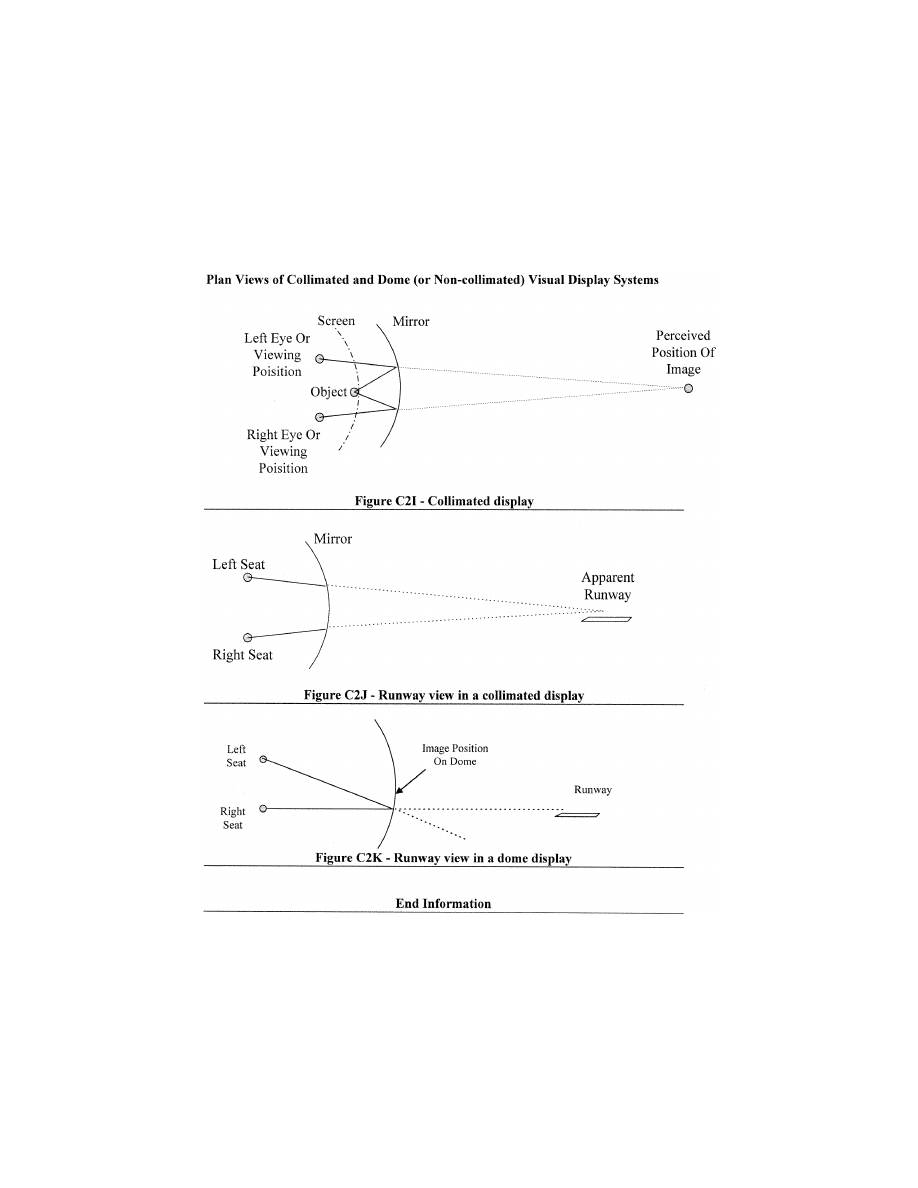
347
Federal Aviation Administration, DOT
Pt. 60, App. C
A
TTACHMENT
3
TO
A
PPENDIX
C
TO
P
ART
60—
S
IMULATOR
S
UBJECTIVE
E
VALUATION
llllllllllllllllllllllll
B
EGIN
QPS R
EQUIREMENTS
1. R
EQUIREMENTS
a. Except for special use airport models, all
airport models required by this part must be
representations of real-world, operational
airports or representations of fictional air-
ports and must meet the requirements set
out in Tables C3B or C3C of this attachment,
as appropriate.
b. If fictional airports are used, the sponsor
must ensure that navigational aids and all
appropriate maps, charts, and other naviga-
tional reference material for the fictional
VerDate Sep<11>2014
14:00 Mar 14, 2024
Jkt 262047
PO 00000
Frm 00357
Fmt 8010
Sfmt 8002
Q:\14\14V2.TXT
PC31
ER09MY08.039</GPH>
aworley on LAPBH6H6L3 with DISTILLER

348
14 CFR Ch. I (1–1–24 Edition)
Pt. 60, App. C
airports (and surrounding areas as nec-
essary) are compatible, complete, and accu-
rate with respect to the visual presentation
and airport model of this fictional airport.
An SOC must be submitted that addresses
navigation aid installation and performance
and other criteria (including obstruction
clearance protection) for all instrument ap-
proaches to the fictional airports that are
available in the simulator. The SOC must
reference and account for information in the
terminal instrument procedures manual and
the construction and availability of the re-
quired maps, charts, and other navigational
material. This material must be clearly
marked ‘‘for training purposes only.’’
c. When the simulator is being used by an
instructor or evaluator for purposes of train-
ing, checking, or testing under this chapter,
only airport models classified as Class I,
Class II, or Class III may be used by the in-
structor or evaluator. Detailed descriptions/
definitions of these classifications are found
in Appendix F of this part.
d. When a person sponsors an FFS main-
tained by a person other than a U.S. certifi-
cate holder, the sponsor is accountable for
that FFS originally meeting, and continuing
to meet, the criteria under which it was
originally qualified and the appropriate Part
60 criteria, including the visual scenes and
airport models that may be used by instruc-
tors or evaluators for purposes of training,
checking, or testing under this chapter.
e. Neither Class II nor Class III airport vis-
ual models are required to appear on the
SOQ, and the method used for keeping in-
structors and evaluators apprised of the air-
port models that meet Class II or Class III
requirements on any given simulator is at
the option of the sponsor, but the method
used must be available for review by the
TPAA.
f. When an airport model represents a real
world airport and a permanent change is
made to that real world airport (e.g., a new
runway, an extended taxiway, a new lighting
system, a runway closure) without a written
extension grant from the responsible Flight
Standards office (described in paragraph 1.g.,
of this section), an update to that airport
model must be made in accordance with the
following time limits:
(1) For a new airport runway, a runway ex-
tension, a new airport taxiway, a taxiway ex-
tension, or a runway/taxiway closure—with-
in 90 days of the opening for use of the new
airport runway, runway extension, new air-
port taxiway, or taxiway extension; or with-
in 90 days of the closure of the runway or
taxiway.
(2) For a new or modified approach light
system—within 45 days of the activation of
the new or modified approach light system.
(3) For other facility or structural changes
on the airport (e.g., new terminal, relocation
of Air Traffic Control Tower)—within 180
days of the opening of the new or changed fa-
cility or structure.
g. If a sponsor desires an extension to the
time limit for an update to a visual scene or
airport model or has an objection to what
must be updated in the specific airport
model requirement, the sponsor must pro-
vide a written extension request to the re-
sponsible Flight Standards office stating the
reason for the update delay and a proposed
completion date or provide an explanation
for the objection, explaining why the identi-
fied airport change will not have an impact
on flight training, testing, or checking. A
copy of this request or objection must also
be sent to the POI/TCPM. The responsible
Flight Standards office will send the official
response to the sponsor and a copy to the
POI/TCPM; however, if there is an objection,
after consultation with the appropriate POI/
TCPM regarding the training, testing, or
checking impact, the responsible Flight
Standards office will send the official re-
sponse to the sponsor and a copy to the POI/
TCPM.
E
ND
QPS R
EQUIREMENTS
llllllllllllllllllllllll
B
EGIN
I
NFORMATION
2. D
ISCUSSION
a. The subjective tests provide a basis for
evaluating the capability of the simulator to
perform over a typical utilization period; de-
termining that the simulator competently
simulates each required maneuver, proce-
dure, or task; and verifying correct oper-
ation of the simulator controls, instruments,
and systems. The items listed in the fol-
lowing Tables are for simulator evaluation
purposes only. They may not be used to limit
or exceed the authorizations for use of a
given level of simulator as described on the
SOQ or as approved by the TPAA. All items
in the following paragraphs are subject to an
examination.
b. The tests in Table C3A, Operations
Tasks, in this attachment address pilot func-
tions, including maneuvers and procedures
(called flight tasks), and are divided by
flight phases. The performance of these tasks
by the responsible Flight Standards office
includes an operational examination of the
visual system and special effects. There are
flight tasks included to address some fea-
tures of advanced technology helicopters and
innovative training programs.
c. The tests in Table C3A, Operations
Tasks, and Table C3G, Instructor Operating
Station, in this attachment address the over-
all function and control of the simulator in-
cluding the various simulated environmental
conditions; simulated helicopter system op-
eration (normal, abnormal, and emergency);
visual system displays; and special effects
VerDate Sep<11>2014
14:00 Mar 14, 2024
Jkt 262047
PO 00000
Frm 00358
Fmt 8010
Sfmt 8002
Q:\14\14V2.TXT
PC31
aworley on LAPBH6H6L3 with DISTILLER

349
Federal Aviation Administration, DOT
Pt. 60, App. C
necessary to meet flight crew training, eval-
uation, or flight experience requirements.
d. All simulated helicopter systems func-
tions will be assessed for normal and, where
appropriate, alternate operations. Normal,
abnormal, and emergency operations associ-
ated with a flight phase will be assessed dur-
ing the evaluation of flight tasks or events
within that flight phase. Simulated heli-
copter systems are listed separately under
‘‘Any Flight Phase’’ to ensure appropriate
attention to systems checks. Operational
navigation systems (including inertial navi-
gation systems, global positioning systems,
or other long-range systems) and the associ-
ated electronic display systems will be eval-
uated if installed. The pilot will include in
his report to the TPAA, the effect of the sys-
tem operation and any system limitation.
e. Simulators demonstrating a satisfactory
circling approach will be qualified for the
circling approach maneuver and may be ap-
proved for such use by the TPAA in the spon-
sor’s FAA-approved flight training program.
To be considered satisfactory, the circling
approach will be flown at maximum gross
weight for landing, with minimum visibility
for the helicopter approach category, and
must allow proper alignment with a landing
runway at least 90
°
different from the instru-
ment approach course while allowing the
pilot to keep an identifiable portion of the
airport in sight throughout the maneuver
(reference—14 CFR 91.175(e)).
f. At the request of the TPAA, the Pilot
may assess the simulator for a special aspect
of a sponsor’s training program during the
functions and subjective portion of an eval-
uation. Such an assessment may include a
portion of a Line Oriented Flight Training
(LOFT) scenario or special emphasis items in
the sponsor’s training program. Unless di-
rectly related to a requirement for the quali-
fication level, the results of such an evalua-
tion would not affect the qualification of the
simulator.
g. This appendix addresses helicopter sim-
ulators at Levels B, C, and D because there
are no Level A Helicopter simulators.
h. The FAA intends to allow the use of
Class III airport models on a limited basis
when the sponsor provides the TPAA (or
other regulatory authority) an appropriate
analysis of the skills, knowledge, and abili-
ties (SKAs) necessary for competent per-
formance of the tasks in which this par-
ticular media element is used. The analysis
should describe the ability of the FFS/visual
media to provide an adequate environment
in which the required SKAs are satisfac-
torily performed and learned. The analysis
should also include the specific media ele-
ment, such as the visual scene or airport
model.
i. The TPAA may accept Class III airport
models without individual observation pro-
vided the sponsor provides the TPAA with an
acceptable description of the process for de-
termining the acceptability of a specific air-
port model, outlines the conditions under
which such an airport model may be used,
and adequately describes what restrictions
will be applied to each resulting airport or
landing area model. Examples of situations
that may warrant Class III model designa-
tion by the TPAA include the following:
(a) Training, testing, or checking on very
low visibility operations, including SMGCS
operations.
(b) Instrument operations training (includ-
ing instrument takeoff, departure, arrival,
approach, and missed approach training,
testing, or checking) using—
(i) A specific model that has been geo-
graphically ‘‘moved’’ to a different location
and aligned with an instrument procedure
for another airport.
(ii) A model that does not match changes
made at the real-world airport (or landing
area for helicopters) being modeled.
(iii) A model generated with an ‘‘off-board’’
or an ‘‘on-board’’ model development tool
(by providing proper latitude/longitude ref-
erence; correct runway or landing area ori-
entation, length, width, marking, and light-
ing information; and appropriate adjacent
taxiway location) to generate a facsimile of
a real world airport or landing area.
j. Previously qualified simulators with cer-
tain early generation Computer Generated
Image (CGI) visual systems, are limited by
the capability of the Image Generator or the
display system used. These systems are:
(1) Early CGI visual systems that are ex-
empt from the necessity of including runway
numbers as a part of the specific runway
marking requirements are:
(a) Link NVS and DNVS.
(b) Novoview 2500 and 6000.
(c) FlightSafety VITAL series up to, and
including, VITAL III, but not beyond.
(d) Redifusion SP1, SP1T, and SP2.
(2) Early CGI visual systems are excepted
from the necessity of including runway num-
bers unless the runway is used for LOFT
training sessions. These LOFT airport mod-
els require runway numbers, but only for the
specific runway end (one direction) used in
the LOFT session. The systems required to
display runway numbers only for LOFT
scenes are:
(a) FlightSafety VITAL IV.
(b) Redifusion SP3 and SP3T.
(c) Link-Miles Image II.
(3) The following list of previously quali-
fied CGI and display systems are incapable of
generating blue lights. These systems are
not required to have accurate taxi-way edge
lighting are:
(a) Redifusion SP1 and SP1T.
(b) FlightSafety Vital IV.
(c) Link-Miles Image II and Image IIT
(d) XKD displays (even though the XKD
image generator is capable of generating
VerDate Sep<11>2014
14:00 Mar 14, 2024
Jkt 262047
PO 00000
Frm 00359
Fmt 8010
Sfmt 8002
Q:\14\14V2.TXT
PC31
aworley on LAPBH6H6L3 with DISTILLER

350
14 CFR Ch. I (1–1–24 Edition)
Pt. 60, App. C
blue colored lights, the display cannot ac-
commodate that color).
E
ND
I
NFORMATION
llllllllllllllllllllllll
T
ABLE
C3A—F
UNCTIONS AND
S
UBJECTIVE
T
ESTS
QPS requirements
Entry No.
Operations tasks
Simulator
level
B C D
Tasks in this table are subject to evaluation if appropriate for the helicopter simulated as indicated in the SOQ Configuration
List or the level of simulator qualification involved. Items not installed or not functional on the simulator and, therefore, not ap-
pearing on the SOQ Configuration List, are not required to be listed as exceptions on the SOQ.
1. Preparation for Flight
1.a. .............................
Flight deck check: Switches, indicators, systems, and equipment ......................................
X X X
2. APU/Engine start and run-up
2.a. .............................
Normal start procedures .......................................................................................................
X X X
2.b. .............................
Alternate start procedures .....................................................................................................
X X X
2.c. .............................
Abnormal starts and shutdowns (e.g., hot start, hung start) ................................................
X X X
2.d. .............................
Rotor engagement ................................................................................................................
X X X
2.e. .............................
System checks ......................................................................................................................
X X X
3. Taxiing—Ground
3.a ..............................
Power required to taxi ...........................................................................................................
X X X
3.b. .............................
Brake effectiveness ...............................................................................................................
X X X
3.c. .............................
Ground handling ....................................................................................................................
X X X
3.d. .............................
Water handling (if applicable) ...............................................................................................
X X
3.e. .............................
Abnormal/emergency procedures:
3.e.1. ..........................
Brake system failure .............................................................................................................
X X X
3.e.2. ..........................
Ground resonance ................................................................................................................
X X
3.e.3. ..........................
Dynamic rollover ...................................................................................................................
X X
3.e.4. ..........................
Deployment of emergency floats/water landing ....................................................................
X X
3.e.5. ..........................
Others listed on the SOQ .....................................................................................................
A X X
4. Taxiing—Hover
4.a. .............................
Takeoff to a hover .................................................................................................................
X X X
4.b. .............................
Instrument response:
4.b.1. ..........................
Engine instruments ...............................................................................................................
X X X
4.b.2. ..........................
Flight instruments ..................................................................................................................
X X X
4.b.3. ..........................
Hovering turns .......................................................................................................................
X X X
4.c. .............................
Hover power checks:
4.c.1. ..........................
In ground effect (IGE) ...........................................................................................................
X X X
4.c.2. ..........................
Out of ground effect (OGE) ..................................................................................................
X X X
4.d. .............................
Crosswind/tailwind hover ......................................................................................................
X X X
4.e. .............................
Translating tendency .............................................................................................................
X X X
4.f. ..............................
External load operations:
VerDate Sep<11>2014
14:00 Mar 14, 2024
Jkt 262047
PO 00000
Frm 00360
Fmt 8010
Sfmt 8002
Q:\14\14V2.TXT
PC31
aworley on LAPBH6H6L3 with DISTILLER

351
Federal Aviation Administration, DOT
Pt. 60, App. C
T
ABLE
C3A—F
UNCTIONS AND
S
UBJECTIVE
T
ESTS
—Continued
QPS requirements
Entry No.
Operations tasks
Simulator
level
B C D
4.f.1. ...........................
Hookup ..................................................................................................................................
X X
4.f.2. ...........................
Release .................................................................................................................................
X X
4.f.3. ...........................
Winch operations ..................................................................................................................
X X
4.g. .............................
Abnormal/emergency procedures:
4.g.1. ..........................
Engine failure ........................................................................................................................
X X X
4.g.2. ..........................
Fuel governing system failure ...............................................................................................
X X X
4.g.3. ..........................
Settling with power (OGE) ....................................................................................................
X X X
4.g.4. ..........................
Hovering autorotation ............................................................................................................
X X
4.g.5. ..........................
Stability augmentation system failure ...................................................................................
X X X
4.g.6. ..........................
Directional control malfunction ..............................................................................................
X X X
4.g.7. ..........................
Loss of tail rotor effectiveness (LTE) ....................................................................................
X X
4.g.8. ..........................
Others listed on the SOQ .....................................................................................................
A X X
4.h. .............................
Pre-takeoff checks ................................................................................................................
X X X
5. Takeoff/Translational Flight
5.a. .............................
Forward (up to effective translational lift) .............................................................................
X X
5.b. .............................
Sideward (up to limiting airspeed) ........................................................................................
X X
5.c. .............................
Rearward (up to limiting airspeed) ........................................................................................
X X
6. Takeoff and Departure Phase
6.a. .............................
Normal ...................................................................................................................................
X X X
6.a.1. ..........................
From ground ..........................................................................................................................
X X X
6.a.2. ..........................
From hover ............................................................................................................................
X X X
6.a.2.a. .......................
Cat A .....................................................................................................................................
X X X
6.a.2.b. .......................
Cat B .....................................................................................................................................
X X X
6.a.3. ..........................
Running .................................................................................................................................
X X X
6.a.4. ..........................
Crosswind/tailwind .................................................................................................................
X X X
6.a.5. ..........................
Maximum performance .........................................................................................................
X X X
6.a.6. ..........................
Instrument .............................................................................................................................
X X X
6.a.7. ..........................
Takeoff from a confined area ................................................................................................
X X X
6.a.8. ..........................
Takeoff from a pinnacle/platform ..........................................................................................
X X X
6.a.9. ..........................
Takeoff from a slope .............................................................................................................
X X X
6.a.10. ........................
External load operations .......................................................................................................
X X
6.b. .............................
Abnormal/emergency procedures: ........................................................................................
X X X
6.b.1. ..........................
Takeoff with engine failure after critical decision point (CDP) .............................................
X X X
6.b.1.a. .......................
Cat A .....................................................................................................................................
X X
6.b.1.b. .......................
Cat B .....................................................................................................................................
X X
VerDate Sep<11>2014
14:00 Mar 14, 2024
Jkt 262047
PO 00000
Frm 00361
Fmt 8010
Sfmt 8002
Q:\14\14V2.TXT
PC31
aworley on LAPBH6H6L3 with DISTILLER

352
14 CFR Ch. I (1–1–24 Edition)
Pt. 60, App. C
T
ABLE
C3A—F
UNCTIONS AND
S
UBJECTIVE
T
ESTS
—Continued
QPS requirements
Entry No.
Operations tasks
Simulator
level
B C D
6.c. .............................
Rejected takeoff ....................................................................................................................
6.c.1. ..........................
Land ......................................................................................................................................
X X X
6.c.2. ..........................
Water (if appropriate) ............................................................................................................
X X X
6.d. .............................
Instrument departure .............................................................................................................
X X X
6.e. .............................
Others as listed on the SOQ ................................................................................................
A X X
7. Climb
7.a. .............................
Normal ...................................................................................................................................
X X X
7.b. .............................
Obstacle clearance ...............................................................................................................
X X X
7.c. .............................
Vertical ..................................................................................................................................
X X
7.d. .............................
One engine inoperative .........................................................................................................
X X X
7.e. .............................
Others as listed on the SOQ ................................................................................................
A X X
8. Cruise
8.a ..............................
Performance ..........................................................................................................................
X X X
8.b. .............................
Flying qualities ......................................................................................................................
X X X
8.c. .............................
Turns .....................................................................................................................................
X X X
8.c.1. ..........................
Timed ....................................................................................................................................
X X X
8.c.2. ..........................
Normal ...................................................................................................................................
X X X
8.c.3. ..........................
Steep .....................................................................................................................................
X X X
8.d. .............................
Accelerations and decelerations ...........................................................................................
X X X
8.e. .............................
High speed vibrations ...........................................................................................................
X X X
8.f. ..............................
External Load Operations (see entry 4.f. of this table) ........................................................
X X
8.g. .............................
Abnormal/emergency procedures .........................................................................................
X X X
8.g.1. ..........................
Engine fire .............................................................................................................................
X X X
8.g.2 ...........................
Engine failure ........................................................................................................................
X X X
8.g.3. ..........................
Inflight engine shutdown and restart .....................................................................................
X X X
8.g.4. ..........................
Fuel governing system failures .............................................................................................
X X X
8.g.5. ..........................
Directional control malfunction ..............................................................................................
X X X
8.g.6. ..........................
Hydraulic failure ....................................................................................................................
X X X
8.g.7. ..........................
Stability system failure ..........................................................................................................
X X X
8.g.8. ..........................
Rotor vibrations .....................................................................................................................
X X X
8.g.9. ..........................
Recovery from unusual attitudes ..........................................................................................
X X X
9. Descent
9.a. .............................
Normal ...................................................................................................................................
X X X
9.b. .............................
Maximum rate .......................................................................................................................
X X X
9.c. .............................
Autorotative ...........................................................................................................................
VerDate Sep<11>2014
14:00 Mar 14, 2024
Jkt 262047
PO 00000
Frm 00362
Fmt 8010
Sfmt 8002
Q:\14\14V2.TXT
PC31
aworley on LAPBH6H6L3 with DISTILLER

353
Federal Aviation Administration, DOT
Pt. 60, App. C
T
ABLE
C3A—F
UNCTIONS AND
S
UBJECTIVE
T
ESTS
—Continued
QPS requirements
Entry No.
Operations tasks
Simulator
level
B C D
9.c.1. ..........................
Straight-in ..............................................................................................................................
X X X
9.c.2. ..........................
With turn ................................................................................................................................
X X X
9.d. .............................
External Load ........................................................................................................................
X X
10. Approach
10.a. ...........................
Non-precision ........................................................................................................................
X X X
10.a.1. ........................
All engines operating ............................................................................................................
X X X
10.a.2. ........................
One or more engines inoperative .........................................................................................
X X X
10.a.3. ........................
Approach procedures:
X
X
X
10.a.3.a. .....................
NDB .......................................................................................................................................
X X X
10.a.3.b. .....................
VOR, RNAV, TACAN ............................................................................................................
X X X
10.a.3.c. .....................
ASR .......................................................................................................................................
X X X
10.a.3.d. .....................
Circling ..................................................................................................................................
X X X
10.a.3.e. .....................
Helicopter only ......................................................................................................................
X X X
10.a.4. ........................
Missed approach ...................................................................................................................
X X X
10.a.4.a. .....................
All engines operating ............................................................................................................
X X X
10.a.4.b. .....................
One or more engines inoperative .........................................................................................
X X X
10.b. ...........................
Precision ................................................................................................................................
X X X
10.b.1. ........................
All engines operating ............................................................................................................
X X X
10.b.2. ........................
Manually controlled—one or more engines inoperative .......................................................
X X X
10.b.3. ........................
Approach procedures:
X
X
X
10.b.3.a. .....................
PAR .......................................................................................................................................
X X X
10.b.3.b. .....................
MLS .......................................................................................................................................
X X X
10.b.3.c. .....................
ILS .........................................................................................................................................
X X X
10.b.3.c. .....................
(1) Manual (raw data) ...........................................................................................................
X X X
10.b.3.c. .....................
(2) Flight director only ...........................................................................................................
X X X
10.b.3.c. .....................
(3) Autopilot * only .................................................................................................................
X X X
10.b.3.c. .....................
(4) Cat I .................................................................................................................................
X X X
10.b.3.c. .....................
(5) Cat II ................................................................................................................................
X X X
10.b.4. ........................
Missed approach:
10.b.4.a. .....................
All engines operating ............................................................................................................
X X X
10.b.4.b. .....................
One or more engines inoperative .........................................................................................
X X X
10.b.4.c. .....................
Stability system failure ..........................................................................................................
X X X
10.c. ...........................
Others as listed on the SOQ ................................................................................................
A X X
11. Landings and Approaches to Landings
11.a. ...........................
Visual Approaches:
VerDate Sep<11>2014
14:00 Mar 14, 2024
Jkt 262047
PO 00000
Frm 00363
Fmt 8010
Sfmt 8002
Q:\14\14V2.TXT
PC31
aworley on LAPBH6H6L3 with DISTILLER

354
14 CFR Ch. I (1–1–24 Edition)
Pt. 60, App. C
T
ABLE
C3A—F
UNCTIONS AND
S
UBJECTIVE
T
ESTS
—Continued
QPS requirements
Entry No.
Operations tasks
Simulator
level
B C D
11.a.1. ........................
Normal ...................................................................................................................................
X X X
11.a.2. ........................
Steep .....................................................................................................................................
X X X
11.a.3. ........................
Shallow ..................................................................................................................................
X X X
11.a.4. ........................
Crosswind ..............................................................................................................................
X X X
11.a.5. ........................
Category A profile .................................................................................................................
X X
11.a.6. ........................
Category B profile .................................................................................................................
X X
11.a.7. ........................
External Load ........................................................................................................................
X X
11.b. ...........................
Abnormal/emergency procedures:
11.b.1. ........................
Directional control failure ......................................................................................................
X X X
11.b.2. ........................
Hydraulics failure ...................................................................................................................
X X X
11.b.3. ........................
Fuel governing failure ...........................................................................................................
X X X
11.b.4. ........................
Autorotation ...........................................................................................................................
X X X
11.b.5. ........................
Stability system failure ..........................................................................................................
X X X
11.b.6. ........................
Others listed on the SOQ .....................................................................................................
A X X
11c. ............................
Landings:
11.c.1. ........................
Normal:
11.c.1.a. .....................
Running .................................................................................................................................
X X X
11.c.1.b. .....................
From Hover ...........................................................................................................................
X X X
11.c.2. ........................
Pinnacle/platform ...................................................................................................................
X X X
11.c.3. ........................
Confined area ........................................................................................................................
X X X
11.c.4. ........................
Slope .....................................................................................................................................
X X
11.c.5. ........................
Crosswind ..............................................................................................................................
X X X
11.c.6. ........................
Tailwind .................................................................................................................................
X X X
11.c.7. ........................
Rejected Landing ..................................................................................................................
X X X
11.c.8. ........................
Abnormal/emergency procedures:
11.c.8.a. .....................
From autorotation ..................................................................................................................
X X
11.c.8.b. .....................
One or more engines inoperative .........................................................................................
X X X
11.c.8.c. .....................
Directional control failure ......................................................................................................
X X X
11.c.8.d. .....................
Hydraulics failure ...................................................................................................................
X X X
11.c.8.e. .....................
Stability augmentation system failure ...................................................................................
X X X
11.c.9. ........................
Other (listed on the SOQ) .....................................................................................................
A X X
12. Any Flight Phase
12.a.1. ........................
Air conditioning ......................................................................................................................
X X X
12.a.2. ........................
Anti-icing/deicing ...................................................................................................................
X X X
12.a.3. ........................
Auxiliary power-plant .............................................................................................................
X X X
VerDate Sep<11>2014
14:00 Mar 14, 2024
Jkt 262047
PO 00000
Frm 00364
Fmt 8010
Sfmt 8002
Q:\14\14V2.TXT
PC31
aworley on LAPBH6H6L3 with DISTILLER

355
Federal Aviation Administration, DOT
Pt. 60, App. C
T
ABLE
C3A—F
UNCTIONS AND
S
UBJECTIVE
T
ESTS
—Continued
QPS requirements
Entry No.
Operations tasks
Simulator
level
B C D
12.a.4. ........................
Communications ....................................................................................................................
X X X
12.a.5. ........................
Electrical ................................................................................................................................
X X X
12.a.6. ........................
Fire detection and suppression .............................................................................................
X X X
12.a.7. ........................
Stabilizer ................................................................................................................................
X X X
12.a.8. ........................
Flight controls ........................................................................................................................
X X X
12.a.9. ........................
Fuel and oil ...........................................................................................................................
X X X
12.a.10. ......................
Hydraulic ...............................................................................................................................
X X X
12.a.11. ......................
Landing gear .........................................................................................................................
X X X
12.a.12. ......................
Oxygen ..................................................................................................................................
X X X
12.a.13. ......................
Pneumatic .............................................................................................................................
X X X
12.a.14. ......................
Powerplant ............................................................................................................................
X X X
12.a.15. ......................
Flight control computers ........................................................................................................
X X X
12.a.16. ......................
Stability and control augmentation ........................................................................................
X X X
12.b. ...........................
Flight management and guidance system:
12.b.1. ........................
Airborne radar .......................................................................................................................
X X X
12.b.2. ........................
Automatic landing aids ..........................................................................................................
X X X
12.b.3. ........................
Autopilot ................................................................................................................................
X X X
12.b.4. ........................
Collision avoidance system ...................................................................................................
X X X
12.b.5. ........................
Flight data displays ...............................................................................................................
X X X
12.b.6. ........................
Flight management computers .............................................................................................
X X X
12.b.7. ........................
Heads-up displays .................................................................................................................
X X X
12.b.8. ........................
Navigation systems ...............................................................................................................
X X X
12.c. ...........................
Airborne procedures:
12.c.1. ........................
Holding ..................................................................................................................................
X X X
12.c.2. ........................
Air hazard avoidance ............................................................................................................
X X X
12.c.3. ........................
Retreating blade stall recovery .............................................................................................
X X X
12.c.4. ........................
Mast bumping ........................................................................................................................
X X X
12.c.5 .........................
Loss of directional control .....................................................................................................
X X X
12.c.6. ........................
Loss of tail rotor effectiveness ..............................................................................................
X X
12.c.7. ........................
Other (listed on the SOQ) .....................................................................................................
A X X
13. Engine Shutdown and Parking
13.a. ...........................
Engine and systems operation .............................................................................................
X X X
13.b. ...........................
Parking brake operation ........................................................................................................
X X X
13.c. ...........................
Rotor brake operation ...........................................................................................................
X X X
VerDate Sep<11>2014
14:00 Mar 14, 2024
Jkt 262047
PO 00000
Frm 00365
Fmt 8010
Sfmt 8002
Q:\14\14V2.TXT
PC31
aworley on LAPBH6H6L3 with DISTILLER
356
14 CFR Ch. I (1–1–24 Edition)
Pt. 60, App. C
T
ABLE
C3A—F
UNCTIONS AND
S
UBJECTIVE
T
ESTS
—Continued
QPS requirements
Entry No.
Operations tasks
Simulator
level
B C D
13.d. ...........................
Abnormal/emergency procedures .........................................................................................
X X X
* ‘‘Autopilot’’ means attitude retention mode of operation.
Note: An ‘‘A’’ in the table indicates that the system, task, or procedure may be examined if the appropriate aircraft system or
control is simulated in the FFS and is working properly.
T
ABLE
C3B—F
UNCTIONS AND
S
UBJECTIVE
T
ESTS
QPS requirements
Entry No.
Visual requirements for qualification at the stated level
class I airport or landing area models
Simulator
level
B C D
This table specifies the minimum airport visual model content and functionality to qualify a simulator at the indicated level. This
table applies only to the airport scenes required for simulator qualification; i.e., two helicopter landing area models for Level B
simulators; four helicopter landing area models for Level C and Level D simulators.
1. ..............
Functional test content requirements
The following is the minimum airport/landing area model content requirement to satisfy visual capability tests, and
provides suitable visual cues to allow completion of all functions and subjective tests described in this attachment
for simulators at Level B.
1.a. ...........
A minimum of one (1) representative airport and one (1) representative helicopter landing area
model. The airport and the helicopter landing area may be contained within the same model. If
but if this option is selected, the approach path to the airport runway(s) and the approach path to
the helicopter landing area must be different. The model(s) used to meet the following require-
ments may be demonstrated at either a fictional or a real-world airport or helicopter landing area,
but each must be acceptable to the sponsor’s TPAA, selectable from the IOS, and listed on the
SOQ.
X
1.b. ...........
The fidelity of the visual scene must be sufficient for the aircrew to visually identify the airport and/or
helicopter landing area; determine the position of the simulated helicopter within the visual scene;
successfully accomplish take-offs, approaches, and landings; and maneuver around the airport on
the ground, or hover taxi, as necessary.
X
1.c. ...........
Runways:
1.c.1. ........
Visible runway number ............................................................................................................................
X
1.c.2. ........
Runway threshold elevations and locations must be modeled to provide sufficient correlation with
helicopter systems (e.g., altimeter).
X
1.c.3. ........
Runway surface and markings ...............................................................................................................
X
1.c.4. ........
Lighting for the runway in use including runway edge and centerline ...................................................
X
1.c.5. ........
Lighting, visual approach aid (VASI or PAPI) and approach lighting of appropriate colors ..................
X
1.c.6. ........
Representative taxiway lights .................................................................................................................
X
1.d. ...........
Other helicopter landing area:
1.d.1. ........
Standard heliport designation (‘‘H’’) marking, properly sized and oriented ............................................
X
1.d.2. ........
Perimeter markings for the Touchdown and Lift-Off Area (TLOF) or the Final Approach and Takeoff
Area (FATO), as appropriate.
X
1.d.3. ........
Perimeter lighting for the TLOF or the FATO areas, as appropriate .....................................................
X
1.d.4. ........
Appropriate markings and lighting to allow movement from the runway or helicopter landing area to
another part of the landing facility.
X
2. ..............
Functional test content requirements for Level C and Level D simulators
VerDate Sep<11>2014
14:00 Mar 14, 2024
Jkt 262047
PO 00000
Frm 00366
Fmt 8010
Sfmt 8002
Q:\14\14V2.TXT
PC31
aworley on LAPBH6H6L3 with DISTILLER
357
Federal Aviation Administration, DOT
Pt. 60, App. C
T
ABLE
C3B—F
UNCTIONS AND
S
UBJECTIVE
T
ESTS
—Continued
QPS requirements
Entry No.
Visual requirements for qualification at the stated level
class I airport or landing area models
Simulator
level
B C D
The following is the minimum airport/landing area model content requirement to satisfy visual capability tests, and
provide suitable visual cues to allow completion of all functions and subjective tests described in this attachment
for simulators at Level C and Level D. Not all of the elements described in this section must be found in a single
airport/landing area scene. However, all of the elements described in this section must be found throughout a com-
bination of the four (4) airport/landing area models described in entry 2.a. The representations of the hazards (as
described in 2.d.) must be ‘‘hard objects’’ that interact as such if contacted by the simulated helicopter. Additionally,
surfaces on which the helicopter lands must be ‘‘hard surfaces.’’ The model(s) used to meet the following require-
ments must be demonstrated at either a fictional or a real-world airport or helicopter landing area, and each must
be acceptable to the sponsor’s TPAA, selectable from the IOS, and listed on the SOQ.
2.a. ...........
There must be at least the following airport/helicopter landing areas.
2.a.1. ........
At least one (1) representative airport ....................................................................................................
X X
2.a.2. ........
At least three representative non-airport landing areas, as follows:
2.a.2.a ......
At least one (1) representative helicopter landing area situated on a substantially elevated surface
with respect to the surrounding structures or terrain (e.g., building top, offshore oil rig).
X X
2.a.2.b. .....
At least one (1) helicopter landing area that meets the definition of a ‘‘confined landing area’’ ...........
X
X
2.a.2.c. .....
At least one (1) helicopter landing area on a sloped surface where the slope is at least 2
1
⁄
2
°
............
X X
2.b. ...........
For each of the airport/helicopter landing areas described in 2.a., the simulator must be able to pro-
vide at least the following:
X X
2.b.1. ........
A night and twilight (dusk) environment. ................................................................................................
X X
2.b.2. ........
A daylight environment ...........................................................................................................................
X
2.c. ...........
Non-airport helicopter landing areas must have the following:
2.c.1. ........
Representative buildings, structures, and lighting within appropriate distances ....................................
X X
2.c.2. ........
Representative moving and static clutter (e.g., other aircraft, power carts, tugs, fuel trucks) ...............
X
X
2.c.3. ........
Representative depiction of terrain and obstacles as well as significant and identifiable natural and
cultural features, within 25 NM of the reference landing area.
X X
2.c.4. ........
Standard heliport designation (‘‘H’’) marking, properly sized and oriented ............................................
X X
2.c.5. ........
Perimeter markings for the Touchdown and Lift-Off Area (TLOF) or the Final Approach and Takeoff
Area (FATO), as appropriate.
X X
2.c.6. ........
Perimeter lighting for the TLOF or the FATO areas, as appropriate .....................................................
X X
2.c.7. ........
Appropriate markings and lighting to allow movement from the area to another part of the landing
facility, if appropriate.
X X
2.c.8. ........
Representative markings, lighting, and signage, including a windsock that gives appropriate wind
cues.
X X
2.c.9. ........
Appropriate markings, lighting, and signage necessary for position identification, and to allow move-
ment from the landing area to another part of the landing facility.
X X
2.c.10. ......
Representative moving and static ground traffic (e.g., vehicular and aircraft), including the ability to
present surface hazards (e.g., conflicting traffic, vehicular or aircraft, on or approaching the land-
ing area).
X X
2.c.11. ......
Portrayal of landing surface contaminants, including lighting reflections when wet and partially ob-
scured lights when snow is present, or suitable alternative effects.
X X
2.d. ...........
All of the following three (3) hazards must be presented in a combination of the three (3) non-airport landing areas
(described in entry 2.a.2. of this table) and each of these non-airport landing areas must have at least one of the
following hazards:
2.d.1. ........
Other airborne traffic ...............................................................................................................................
X X
VerDate Sep<11>2014
14:00 Mar 14, 2024
Jkt 262047
PO 00000
Frm 00367
Fmt 8010
Sfmt 8002
Q:\14\14V2.TXT
PC31
aworley on LAPBH6H6L3 with DISTILLER

358
14 CFR Ch. I (1–1–24 Edition)
Pt. 60, App. C
T
ABLE
C3B—F
UNCTIONS AND
S
UBJECTIVE
T
ESTS
—Continued
QPS requirements
Entry No.
Visual requirements for qualification at the stated level
class I airport or landing area models
Simulator
level
B C D
2.d.2. ........
Buildings, trees, or other vertical obstructions in the immediate landing area ......................................
X X
2.d.3. ........
Suspended wires in the immediate landing area ...................................................................................
X X
2.e. ...........
Airport applications. Each airport must have the following:
2.e.1. ........
At least one runway designated as ‘‘in-use’’, appropriately marked and capable of being lighted fully
X
X
2.e.2. ........
Runway threshold elevations and locations must be modeled to provide sufficient correlation with
helicopter systems (e.g., HGS, GPS, altimeter). Slopes in runways, taxiways, and ramp areas, if
depicted in the visual scene, may not cause distracting or unrealistic effects, including pilot eye-
point height variation.
X X X
2.e.3. ........
Appropriate approach lighting systems and airfield lighting for a VFR circuit and landing, non-preci-
sion approaches and landings, and precision approaches and landings, as appropriate..
X X
2.e.4. ........
Representative taxiway lights .................................................................................................................
X
3. ..............
Airport or landing area model management
The following is the minimum visual scene management requirements
3.a. ...........
Runway and helicopter landing area approach lighting must fade into view in accordance with the
environmental conditions set in the simulator.
X X X
3.b. ...........
The direction of strobe lights, approach lights, runway edge lights, visual landing aids, runway cen-
terline lights, threshold lights, touchdown zone lights, and TLOF or FATO lights must be replicated.
X X X
4. ..............
Visual feature recognition.
The following are the minimum distances at which runway features must be visible. Distances are measured from
runway threshold or a helicopter landing area to a helicopter aligned with the runway or helicopter landing area on
an extended 3
°
glide-slope in simulated meteorological conditions. For circling approaches, all tests apply to the
runway used for the initial approach and to the runway of intended landing
4.a. ...........
For runways: Runway definition, strobe lights, approach lights, and runway edge lights from 5 sm (8
km) of the runway threshold.
X X X
4.b. ...........
For runways: Centerline lights and taxiway definition from 3 sm (5 km) ...............................................
X X X
4.c. ...........
For runways: Visual Approach Aid lights (VASI or PAPI) from 3 sm (5 km) of the threshold ...............
X
4.d. ...........
For runways: Visual Approach Aid lights (VASI or PAPI) from 5 sm (8 km) of the threshold ...............
X
X
4.e. ...........
For runways: Runway threshold lights and touchdown zone lights from 2 sm (3 km) ..........................
X
X
X
4.f. ............
For runways and helicopter landing areas: Markings within range of landing lights for night/twilight
scenes and the surface resolution test on daylight scenes, as required.
X X X
4.g. ...........
For circling approaches, the runway of intended landing and associated lighting must fade into view
in a non-distracting manner.
X X X
4.h. ...........
For helicopter landing areas: Landing direction lights and raised FATO lights from 1 sm (1.5 km) .....
X
X
X
4.i. ............
For helicopter landing areas: Flush mounted FATO lights, TOFL lights, and the lighted windsock
from 0.5 sm (750 m).
X
4.j. ............
Hover taxiway lighting (yellow/blue/yellow cylinders) from TOFL area ..................................................
X
5. ..............
Airport or helicopter landing area model content
VerDate Sep<11>2014
14:00 Mar 14, 2024
Jkt 262047
PO 00000
Frm 00368
Fmt 8010
Sfmt 8002
Q:\14\14V2.TXT
PC31
aworley on LAPBH6H6L3 with DISTILLER
359
Federal Aviation Administration, DOT
Pt. 60, App. C
T
ABLE
C3B—F
UNCTIONS AND
S
UBJECTIVE
T
ESTS
—Continued
QPS requirements
Entry No.
Visual requirements for qualification at the stated level
class I airport or landing area models
Simulator
level
B C D
The following prescribes the minimum requirements for an airport/helicopter landing area model and identifies other
aspects of the environment that must correspond with that model for simulators at Level B, Level C, and Level D.
For circling approaches, all tests apply to the runway used for the initial approach and to the runway of intended
landing. If all runways or landing areas in a visual model used to meet the requirements of this attachment are not
designated as ‘‘in use,’’ then the ‘‘in use’’ runways/landing areas must be listed on the SOQ (e.g., KORD, Rwys
9R, 14L, 22R). Models of airports or helicopter landing areas with more than one runway or landing area must
have all significant runways or landing areas not ‘‘in-use’’ visually depicted for airport runway/landing area recogni-
tion purposes. The use of white or off-white light strings that identify the runway or landing area for twilight and
night scenes are acceptable for this requirement; and rectangular surface depictions are acceptable for daylight
scenes. A visual system’s capabilities must be balanced between providing visual models with an accurate rep-
resentation of the airport and a realistic representation of the surrounding environment. Each runway or helicopter
landing area designated as an ‘‘in-use’’ runway or area must include the following detail that is developed using
airport pictures, construction drawings and maps, or other similar data, or developed in accordance with published
regulatory material; however, this does not require that such models contain details that are beyond the design ca-
pability of the currently qualified visual system. Only one ‘‘primary’’ taxi route from parking to the runway end or
helicopter takeoff/landing area will be required for each ‘‘in-use’’ runway or helicopter takeoff/landing area.
5.a. ...........
The surface and markings for each ‘‘in-use’’ runway or helicopter landing area must include the following:
5.a.1. ........
For airports: Runway threshold markings, runway numbers, touchdown zone markings, fixed dis-
tance markings, runway edge markings, and runway centerline stripes.
X X X
5.a.2. ........
For helicopter landing areas: Markings for standard heliport identification (‘‘H’’) and TOFL, FATO,
and safety areas.
X X X
5.b. ...........
The lighting for each ‘‘in-use’’ runway or helicopter landing area must include the following:
5.b.1. ........
For airports: Runway approach, threshold, edge, end, centerline (if applicable), touchdown zone (if
applicable), leadoff, and visual landing aid lights or light systems for that runway.
X X X
5.b.2. ........
For helicopter landing areas: landing direction, raised and flush FATO, TOFL, windsock lighting .......
X
X
X
5.c. ...........
The taxiway surface and markings associated with each ‘‘in-use’’ runway or helicopter landing area must include
the following:
5.c.1. ........
For airports: Taxiway edge, centerline (if appropriate), runway hold lines, and ILS critical area(s) .....
X
X
X
5.c.2. ........
For helicopter landing areas: taxiways, taxi routes, and aprons ............................................................
X X X
5.d. ...........
The taxiway lighting associated with each ‘‘in-use’’ runway or helicopter landing area must include the following:
5.d.1. ........
For airports: Runway edge, centerline (if appropriate), runway hold lines, ILS critical areas ...............
X
X
X
5.d.2. ........
For helicopter landing areas: taxiways, taxi routes, and aprons ............................................................
X X X
5.d.3. ........
For airports: taxiway lighting of correct color ..........................................................................................
X
5.e. ...........
Airport signage associated with each ‘‘in-use’’ runway or helicopter landing area must include the following:
5.e.1. ........
For airports: Signs for runway distance remaining, intersecting runway with taxiway, and intersecting
taxiway with taxiway.
X X X
5.e.2. ........
For helicopter landing areas: as appropriate for the model used ..........................................................
X X X
5.f. ............
Required visual model correlation with other aspects of the airport or helicopter landing environment simulation:
5.f.1. .........
The airport or helicopter landing area model must be properly aligned with the navigational aids that
are associated with operations at the ‘‘in-use’’ runway or helicopter landing area.
X X X
5.f.2. .........
The simulation of runway or helicopter landing area contaminants must be correlated with the dis-
played runway surface and lighting where applicable.
X X
6. ..............
Correlation with helicopter and associated equipment
The following are the minimum correlation comparisons that must be made for simulators at Level B, Level C, and
Level D
6.a. ...........
Visual system compatibility with aerodynamic programming .................................................................
X X X
VerDate Sep<11>2014
14:00 Mar 14, 2024
Jkt 262047
PO 00000
Frm 00369
Fmt 8010
Sfmt 8002
Q:\14\14V2.TXT
PC31
aworley on LAPBH6H6L3 with DISTILLER

360
14 CFR Ch. I (1–1–24 Edition)
Pt. 60, App. C
T
ABLE
C3B—F
UNCTIONS AND
S
UBJECTIVE
T
ESTS
—Continued
QPS requirements
Entry No.
Visual requirements for qualification at the stated level
class I airport or landing area models
Simulator
level
B C D
6.b. ...........
Visual cues to assess sink rate and depth perception during landings .................................................
X X X
6.c. ...........
Accurate portrayal of environment relating to flight simulator attitudes .................................................
X X X
6.d. ...........
The visual scene must correlate with integrated helicopter systems (e.g., terrain, traffic and weather
avoidance systems and Head-up Guidance System (HGS)).
X X
6.e. ...........
Representative visual effects for each visible, own-ship, helicopter external light(s)—taxi and landing
light lobes (including independent operation, if appropriate).
X X X
6.f. ............
The effect of rain removal devices .........................................................................................................
X X
7. ..............
Scene quality
The following are the minimum scene quality tests that must be conducted for simulators at Level B, Level C, and
Level D.
7.a. ...........
Surfaces and textural cues must be free from apparent and distracting quantization (aliasing) ...........
X
X
7.b. ...........
System capable of portraying full color realistic textural cues ...............................................................
X X
7.c. ...........
The system light points must be free from distracting jitter, smearing or streaking ..............................
X X X
7.d. ...........
Demonstration of occulting through each channel of the system in an operational scene ...................
X
X
X
7.e. ...........
Demonstration of a minimum of ten levels of occulting through each channel of the system in an
operational scene.
X X
7.f. ............
System capable of providing focus effects that simulate rain. ...............................................................
X X
7.g. ...........
System capable of providing focus effects that simulate light point perspective growth .......................
X
X
7.h. ...........
Runway light controls capable of six discrete light steps (0–5) .............................................................
X X X
8. ..............
Environmental effects.
The following are the minimum environmental effects that must be available in simulators at Level B, Level C, and
Level D.
8.a. ...........
The displayed scene corresponding to the appropriate surface contaminants and include appropriate
lighting reflections for wet, partially obscured lights for snow, or alternative effects.
X
8.b. ...........
Special weather representations which include:
8.b.1. ........
The sound, motion and visual effects of light, medium and heavy precipitation near a thunderstorm
on take-off, approach, and landings at and below an altitude of 2,000 ft (600 m) above the sur-
face and within a radius of 10 sm (16 km) from the airport or helicopter landing area.
X
8.b.2. ........
One airport or helicopter landing area with a snow scene to include terrain snow and snow-covered
surfaces.
X
8.c. ...........
In-cloud effects such as variable cloud density, speed cues and ambient changes .............................
X
X
8.d. ...........
The effect of multiple cloud layers representing few, scattered, broken and overcast conditions giv-
ing partial or complete obstruction of the ground scene.
X X
8.e. ...........
Visibility and RVR measured in terms of distance. Visibility/RVR checked at 2,000 ft (600 m) above
the airport or helicopter landing area and at two heights below 2,000 ft with at least 500 ft of sep-
aration between the measurements. The measurements must be taken within a radius of 10 sm
(16 km) from the airport or helicopter landing area.
X X X
8.f. ............
Patchy fog giving the effect of variable RVR ..........................................................................................
X
8.g. ...........
Effects of fog on airport lighting such as halos and defocus .................................................................
X X
8.h. ...........
Effect of own-ship lighting in reduced visibility, such as reflected glare, including landing lights,
strobes, and beacons.
X X
8.i. ............
Wind cues to provide the effect of blowing snow or sand across a dry runway or taxiway selectable
from the instructor station.
X
VerDate Sep<11>2014
14:00 Mar 14, 2024
Jkt 262047
PO 00000
Frm 00370
Fmt 8010
Sfmt 8002
Q:\14\14V2.TXT
PC31
aworley on LAPBH6H6L3 with DISTILLER
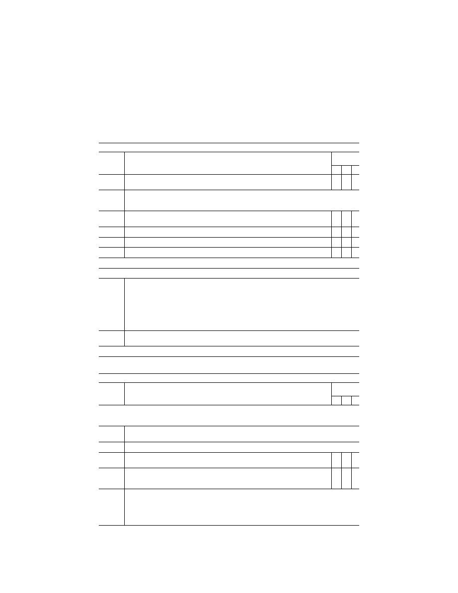
361
Federal Aviation Administration, DOT
Pt. 60, App. C
T
ABLE
C3B—F
UNCTIONS AND
S
UBJECTIVE
T
ESTS
—Continued
QPS requirements
Entry No.
Visual requirements for qualification at the stated level
class I airport or landing area models
Simulator
level
B C D
8.j. ............
‘‘White-out’’ or ‘‘Brown-out’’ effects due to rotor downwash beginning at a distance above the ground
equal to the rotor diameter.
X
9. ..............
Instructor control of the following:
The following are the minimum instructor controls that must be available in Level B, Level C, and Level D simula-
tors, as indicated.
9.a. ...........
Environmental effects, e.g. cloud base, cloud effects, cloud density, visibility in statute miles/ kilo-
meters and RVR in feet/meters.
X X X
9.b. ...........
Airport or helicopter landing area selection ............................................................................................
X X X
9.c. ...........
Airport or helicopter landing area lighting, including variable intensity ..................................................
X X X
9.d. ...........
Dynamic effects including ground and flight traffic .................................................................................
X X
End QPS Requirement
Begin Information
10. ............
An example of being able to ‘‘combine two airport models to achieve two ‘‘in-use’’ runways: One runway des-
ignated as the ‘‘in-use’’ runway in the first model of the airport, and the second runway designated as the ‘‘in-use’’
runway in the second model of the same airport. For example, the clearance is for the ILS approach to Runway
27, Circle to Land on Runway 18 right. Two airport visual models might be used: the first with Runway 27 des-
ignated as the ‘‘in use’’ runway for the approach to runway 27, and the second with Runway 18 Right designated
as the ‘‘in use’’ runway. When the pilot breaks off the ILS approach to runway 27, the instructor may change to the
second airport visual model in which runway 18 Right is designated as the ‘‘in use’’ runway, and the pilot would
make a visual approach and landing. This process is acceptable to the FAA as long as the temporary interruption
due to the visual model change is not distracting to the pilot.
11. ............
Sponsors are not required to provide every detail of a runway, but the detail that is provided should be correct
within reasonable limits.
End Information
T
ABLE
C3C—F
UNCTIONS AND
S
UBJECTIVE
T
ESTS
QPS requirements
Entry No.
Visual scene content additional airport or landing area models beyond minimum required for quali-
fication
Class II airport or landing area models
Simulator
level
B C D
This table specifies the minimum airport or helicopter landing area visual model content and functionality necessary to add vis-
ual models to a simulator’s visual model library (i.e., beyond those necessary for qualification at the stated level) without the
necessity of further involvement of the responsible Flight Standards office or TPAA.
1. ..............
Airport or landing area model management
The following is the minimum visual scene management requirements for simulators at Levels B, C, and D.
1.a. ...........
The installation and direction of the following lights must be replicated for the ‘‘in-use’’ surface:
1.a.1. ........
For ‘‘in-use’’ runways: Strobe lights, approach lights, runway edge lights, visual landing aids, runway
centerline lights, threshold lights, and touchdown zone lights.
X X X
1.a.2. ........
For ‘‘in-use’’ helicopter landing areas: ground level TLOF perimeter lights, elevated TLOF perimeter
lights (if applicable), Optional TLOF lights (if applicable), ground FATO perimeter lights, elevated
TLOF lights (if applicable), landing direction lights.
X X X
2. ..............
Visual feature recognition
The following are the minimum distances at which runway or landing area features must be visible for simulators at
Levels B, C, and D. Distances are measured from runway threshold or a helicopter landing area to an aircraft
aligned with the runway or helicopter landing area on a 3
°
glide-slope from the aircraft to the touchdown point, in
simulated meteorological conditions. For circling approaches, all tests apply to the runway used for the initial ap-
proach and to the runway of intended landing.
VerDate Sep<11>2014
14:00 Mar 14, 2024
Jkt 262047
PO 00000
Frm 00371
Fmt 8010
Sfmt 8002
Q:\14\14V2.TXT
PC31
aworley on LAPBH6H6L3 with DISTILLER

362
14 CFR Ch. I (1–1–24 Edition)
Pt. 60, App. C
T
ABLE
C3C—F
UNCTIONS AND
S
UBJECTIVE
T
ESTS
—Continued
QPS requirements
Entry No.
Visual scene content additional airport or landing area models beyond minimum required for quali-
fication
Class II airport or landing area models
Simulator
level
B C D
2.a. ...........
For Runways:
2.a.1. ........
Strobe lights, approach lights, and edge lights from 5 sm (8 km) of the threshold ...............................
X X X
2.a.2. ........
Centerline lights and taxiway definition from 3 sm (5 km) .....................................................................
X X X
2.a.3. ........
Visual Approach Aid lights (VASI or PAPI) from 3 sm (5 km) of the threshold .....................................
X
2.a.4. ........
Visual Approach Aid lights (VASI or PAPI) from 5 sm (8 km) of the threshold .....................................
X X
2.a.5. ........
Threshold lights and touchdown zone lights from 2 sm (3 km) .............................................................
X X X
2.a.6. ........
Markings within range of landing lights for night/twilight (dusk) scenes and as required by the sur-
face resolution test on daylight scenes.
X X X
2.a.7. ........
For circling approaches, the runway of intended landing and associated lighting must fade into view
in a non-distracting manner.
X X X
2.b. ...........
For Helicopter landing areas:
2.b.1. ........
Landing direction lights and raised FATO lights from 1 sm (1.5 km) ....................................................
X X X
2.b.2. ........
Flush mounted FATO lights, TOFL lights, and the lighted windsock from 0.5 sm (750 m) ..................
X
X
2.b.3. ........
Hover taxiway lighting (yellow/blue/yellow cylinders) from TOFL area ..................................................
X X
2.b.4. ........
Markings within range of landing lights for night/twilight (dusk) scenes and as required by the sur-
face resolution test on daylight scenes.
X X X
3. ..............
Airport or Helicopter landing area model content
The following prescribes the minimum requirements for what must be provided in an airport visual model and iden-
tifies other aspects of the airport environment that must correspond with that model for simulators at Level B, C,
and D. The detail must be developed using airport pictures, construction drawings and maps, or other similar data,
or developed in accordance with published regulatory material; however, this does not require that airport or heli-
copter landing area models contain details that are beyond the designed capability of the currently qualified visual
system. For circling approaches, all requirements of this section apply to the runway used for the initial approach
and to the runway of intended landing. Only one ‘‘primary’’ taxi route from parking to the runway end or helicopter
takeoff/landing area will be required for each ‘‘in-use’’ runway or helicopter takeoff/landing area.
3.a. ...........
The surface and markings for each ‘‘in-use’’ runway or helicopter landing area must include the following:
3.a.1. ........
For airports: Runway threshold markings, runway numbers, touchdown zone markings, fixed dis-
tance markings, runway edge markings, and runway centerline stripes.
X X X
3.a.2. ........
For helicopter landing areas: Standard heliport marking (‘‘H’’), TOFL, FATO, and safety areas ..........
X
X
X
3.b. ...........
The lighting for each ‘‘in-use’’ runway or helicopter landing area must include the following:
3.b.1. ........
For airports: Runway approach, threshold, edge, end, centerline (if applicable), touchdown zone (if
applicable), leadoff, and visual landing aid lights or light systems for that runway.
X X X
3.b.2. ........
For helicopter landing areas: Landing direction, raised and flush FATO, TOFL, windsock lighting ......
X
X
X
3.c. ...........
The taxiway surface and markings associated with each ‘‘in-use’’ runway or helicopter landing area must include
the following:
3.c.1. ........
For airports: Taxiway edge, centerline (if appropriate), runway hold lines, and ILS critical area(s) .....
X
X
X
3.c.2. ........
For helicopter landing areas: Taxiways, taxi routes, and aprons ...........................................................
X X X
3.d. ...........
The taxiway lighting associated with each ‘‘in-use’’ runway or helicopter landing area must include the following:
3.d.1. ........
For airports: Runway edge, centerline (if appropriate), runway hold lines, ILS critical areas ...............
X
X
X
3.d.2. ........
For helicopter landing areas: Taxiways, taxi routes, and aprons ...........................................................
X X X
3.d.3. ........
For airports: Taxiway lighting of correct color ........................................................................................
X
4. ..............
Required visual model correlation with other aspects of the airport environment simulation
VerDate Sep<11>2014
14:00 Mar 14, 2024
Jkt 262047
PO 00000
Frm 00372
Fmt 8010
Sfmt 8002
Q:\14\14V2.TXT
PC31
aworley on LAPBH6H6L3 with DISTILLER
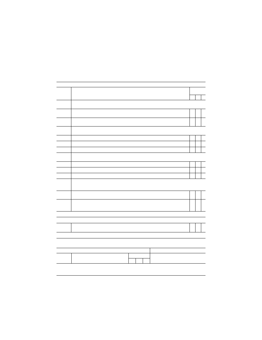
363
Federal Aviation Administration, DOT
Pt. 60, App. C
T
ABLE
C3C—F
UNCTIONS AND
S
UBJECTIVE
T
ESTS
—Continued
QPS requirements
Entry No.
Visual scene content additional airport or landing area models beyond minimum required for quali-
fication
Class II airport or landing area models
Simulator
level
B C D
The following are the minimum visual model correlation tests that must be conducted for Level B, Level C, and
Level D simulators, as indicated.
4.a. ...........
The airport model must be properly aligned with the navigational aids that are associated with oper-
ations at the ‘‘in-use’’ runway.
X X X
4.b. ...........
Slopes in runways, taxiways, and ramp areas, if depicted in the visual scene, must not cause dis-
tracting or unrealistic effects.
X X X
5. ..............
Correlation with helicopter and associated equipment
The following are the minimum correlation comparisons that must be made for simulators at Level B, C, and D.
5.a. ...........
Visual system compatibility with aerodynamic programming .................................................................
X X X
5.b. ...........
Accurate portrayal of environment relating to flight simulator attitudes .................................................
X X X
5.c. ...........
Visual cues to assess sink rate and depth perception during landings .................................................
X X X
6. ..............
Scene quality
The following are the minimum scene quality tests that must be conducted for simulators at Level B, C, and D.
6.a. ...........
Light points free from distracting jitter, smearing or streaking ...............................................................
X X X
6.b. ...........
Surfaces and textural cues free from apparent and distracting quantization (aliasing) .........................
X
X
6.c. ...........
Correct color and realistic textural cues .................................................................................................
X
7. ..............
Instructor controls of the following:
The following are the minimum instructor controls that must be available in Level B, Level C, and Level D simula-
tors, as indicated.
7.a. ...........
Environmental effects, e.g., cloud base (if used), cloud effects, cloud density, visibility in statute
miles/kilometers and RVR in feet/meters.
X X X
7.b. ...........
Airport/Heliport selection .........................................................................................................................
X X X
7.c. ...........
Airport lighting including variable intensity ..............................................................................................
X X X
7.d. ...........
Dynamic effects including ground and flight traffic .................................................................................
X X
End QPS Requirements
Begin Information
8. ..............
Sponsors are not required to provide every detail of a runway or helicopter landing area, but the de-
tail that is provided must be correct within the capabilities of the system.
X X X
End Information
T
ABLE
C3D—F
UNCTIONS AND
S
UBJECTIVE
T
ESTS
QPS requirements
Information
Entry No.
Motion system (and special
aerodynamic model) effects
Simulator level
Notes
B C D
This table specifies motion effects that are required to indicate the threshold at which a flight crewmember must be able to rec-
ognize an event or situation. Where applicable, flight simulator pitch, side loading and directional control characteristics must
be representative of the helicopter.
VerDate Sep<11>2014
14:00 Mar 14, 2024
Jkt 262047
PO 00000
Frm 00373
Fmt 8010
Sfmt 8002
Q:\14\14V2.TXT
PC31
aworley on LAPBH6H6L3 with DISTILLER

364
14 CFR Ch. I (1–1–24 Edition)
Pt. 60, App. C
T
ABLE
C3D—F
UNCTIONS AND
S
UBJECTIVE
T
ESTS
—Continued
QPS requirements
Information
Entry No.
Motion system (and special
aerodynamic model) effects
Simulator level
Notes
B C D
1 ...............
Runway rumble, oleo deflection, ground
speed, uneven runway, runway and taxi-
way centerline light characteristics:
Procedure: After the helicopter has been pre-
set to the takeoff position and then released,
taxi at various speeds with a smooth runway
and note the general characteristics of the
simulated runway rumble effects of oleo de-
flections. Repeat the maneuver with a run-
way roughness of 50%, then with maximum
roughness. Note the associated motion vi-
brations affected by ground speed and run-
way roughness
X
X
X If time permits, different gross weights can
also be selected as this may also affect the
associated vibrations depending on heli-
copter type. The associated motion effects
for the above tests should also include an
assessment of the effects of rolling over
centerline lights, surface discontinuities of
uneven runways, and various taxiway char-
acteristics.
2 ...............
Friction Drag from Skid-type Landing Gear:
Procedure: Perform a running takeoff or a run-
ning landing and note an increase in a fuse-
lage vibration (as opposed to rotor vibration)
due to the friction of dragging the skid along
the surface. This vibration will lessen as the
ground speed decreases
X X
3. ..............
Rotor Out-of-Track and/or Out-of-Balance
condition:
Procedure: Select the malfunction or condition
from the IOS. Start the engine(s) normally
and check for an abnormal vibration for an
Out-of-Track condition and check for an ab-
normal vibration for an Out-of-Balance con-
dition
X
X
X
Does not require becoming airborne. The ab-
normal vibration for Out-of-Track and Out-of-
Balance conditions should be recognized in
the frequency range of the inverse of the
period for each; i.e., 1/P for vertical vibra-
tion, and 1/P for lateral vibration.
4. ..............
Bumps associated with the landing gear:
Procedure: Perform a normal take-off paying
special attention to the bumps that could be
perceptible due to maximum oleo extension
after lift-off
X
X
X When the landing gear is extended or re-
tracted, motion bumps can be felt when the
gear locks into position.
5. ..............
Buffet during extension and retraction of
landing gear:
Procedure: Operate the landing gear. Check
that the motion cues of the buffet experi-
enced represent the actual helicopter
X X X
6. ..............
Failure of Dynamic Vibration Absorber or
similar system as appropriate for the hel-
icopter (e.g., droop stop or static stop):
Procedure: May be accomplished any time the
rotor is engaged. Select the appropriate fail-
ure at the IOS, note an appropriate increase
in vibration and check that the vibration in-
tensity and frequency increases with an in-
crease in RPM and an increase in collective
application
X X X
7. ..............
Tail Rotor Drive Failure:
Procedure: With the engine(s) running and the
rotor engaged—select the malfunction and
note the immediate increase of medium fre-
quency vibration
X
X
X The tail rotor operates in the medium fre-
quency range, normally estimated by multi-
plying the tail rotor gear box ratio by the
main rotor RPM. The failure can be recog-
nized by an increase in the vibrations in this
frequency range.
8. ..............
Touchdown cues for main and nose gear:
Procedure: Conduct several normal ap-
proaches with various rates of descent.
Check that the motion cues for the touch-
down bumps for each descent rate are rep-
resentative of the actual helicopter
X X X
VerDate Sep<11>2014
14:00 Mar 14, 2024
Jkt 262047
PO 00000
Frm 00374
Fmt 8010
Sfmt 8002
Q:\14\14V2.TXT
PC31
aworley on LAPBH6H6L3 with DISTILLER

365
Federal Aviation Administration, DOT
Pt. 60, App. C
T
ABLE
C3D—F
UNCTIONS AND
S
UBJECTIVE
T
ESTS
—Continued
QPS requirements
Information
Entry No.
Motion system (and special
aerodynamic model) effects
Simulator level
Notes
B C D
9. ..............
Tire failure dynamics:
Procedure: Simulate a single tire failure and a
multiple tire failure
X
X
The pilot may notice some yawing with a mul-
tiple tire failure selected on the same side.
This should require the use of the pedal to
maintain control of the helicopter. Depend-
ent on helicopter type, a single tire failure
may not be noticed by the pilot and may not
cause any special motion effect. Sound or
vibration may be associated with the actual
tire losing pressure.
10. ............
Engine malfunction and engine damage:
Procedure: The characteristics of an engine
malfunction as prescribed in the malfunction
definition document for the particular flight
simulator must describe the special motion
effects felt by the pilot. Note the associated
engine instruments varying according to the
nature of the malfunction and note the rep-
lication of the effects of the airframe vibra-
tion
X X X
11. ............
Tail boom strikes:
Procedure: Tail-strikes can be checked by
over-rotation of the helicopter at a quick
stop or autorotation to the ground
X
X
X
The motion effect should be felt as a notice-
able nose down pitching moment.
12. ............
Vortex Ring State (Settling with Power):
Procedure: Specific procedures may differ be-
tween helicopters and may be prescribed by
the Helicopter Manufacturer or other subject
matter expert. However, the following infor-
mation is provided for illustrative purposes
* * * To enter the maneuver, reduce power
below hover power. Hold altitude with aft cy-
clic until the airspeed approaches 20 knots.
Then allow the sink rate to increase to 300
feet per minute or more as the attitude is
adjusted to obtain an airspeed of less than
10 knots
X
X
When the aircraft begins to shudder, the appli-
cation of additional up collective increases
the vibration and sink rate. One recovery
method is to decrease collective to enter
vertical autorotation and/or use cyclic inputs
to gain horizontal airspeed and exit from
vortex ring state.
13. ............
Retreating Blade Stall:
Procedure: Specific procedures may differ be-
tween helicopters and may be prescribed by
the Helicopter Manufacturer or other subject
matter expert. However, the following infor-
mation is provided for illustrative purposes:
To enter the maneuver, increase forward
airspeed; the effect will be recognized
through the development of a low frequency
vibration, pitching up of the nose, and a roll
in the direction of the retreating blade. High
weight, low rotor RPM, high density altitude,
turbulence or steep, abrupt turns are all con-
ducive to retreating blade stall at high for-
ward airspeeds
X
X
Correct recovery from retreating blade stall re-
quires the collective to be lowered first,
which reduces blade angles and the angle
of attack. Aft cyclic can then be used to
slow the helicopter.
VerDate Sep<11>2014
14:00 Mar 14, 2024
Jkt 262047
PO 00000
Frm 00375
Fmt 8010
Sfmt 8002
Q:\14\14V2.TXT
PC31
aworley on LAPBH6H6L3 with DISTILLER
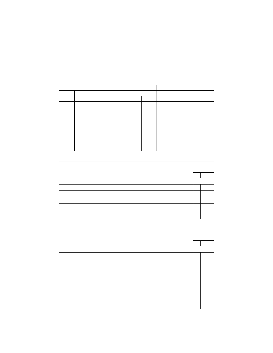
366
14 CFR Ch. I (1–1–24 Edition)
Pt. 60, App. C
T
ABLE
C3D—F
UNCTIONS AND
S
UBJECTIVE
T
ESTS
—Continued
QPS requirements
Information
Entry No.
Motion system (and special
aerodynamic model) effects
Simulator level
Notes
B C D
14. ............
Translational Lift Effects:
Procedure: From a stabilized in-ground-effect
(IGE) Hover begin a forward acceleration.
When passing through the effective
translational lift range, the noticeable effect
will be a possible nose pitch-up in some hel-
icopters, an increase in the rate of climb,
and a temporary increase in vibration level
(in some cases this vibration may be pro-
nounced). This effect is experienced again
upon deceleration through the appropriate
speed range. During deceleration, the pitch
and rate of climb will have the reverse ef-
fect, but there will be a similar, temporary in-
crease in vibration level
X X X
T
ABLE
C3E—F
UNCTIONS AND
S
UBJECTIVE
T
ESTS
QPS Requirements
Entry num-
ber
Sound system
Simulator level
B C D
The following checks are performed during a normal flight profile, motion system ON.
1. ..............
Precipitation. ......................................................................................................................................
X X
2. ..............
Rain removal equipment. ..................................................................................................................
X X
3. ..............
Helicopter noises used by the pilot for normal helicopter operation. ...............................................
X X
4. ..............
Abnormal operations for which there are associated sound cues, including engine malfunctions,
landing gear or tire malfunctions, tail boom.
X X
5. ..............
Sound of a crash when the flight simulator is landed in excess of limitations ................................
X
X
T
ABLE
C3F—F
UNCTIONS AND
S
UBJECTIVE
T
ESTS
QPS Requirements
Entry num-
ber
Special effects
Simulator level
B C D
This table specifies the minimum special effects necessary for the specified simulator level.
1. ..............
Braking Dynamics: ..........................................................................................................................
Representations of the dynamics of brake failure (flight simulator pitch, side-loading, and direc-
tional control characteristics representative of the helicopter), including antiskid and decreased
brake efficiency due to high brake temperatures (based on helicopter related data), sufficient
to enable pilot identification of the problem and implementation of appropriate procedures.
X X
2. ..............
Effects of Airframe and Engine Icing: Required only for those helicopters authorized for
operations in known icing conditions.
Procedure: With the simulator airborne, in a clean configuration, nominal altitude and cruise air-
speed, autopilot on and auto-throttles off, engine and airfoil anti-ice/de-ice systems deacti-
vated; activate icing conditions at a rate that allows monitoring of simulator and systems re-
sponse.
Icing recognition will include an increase in gross weight, airspeed decay, change in simulator
pitch attitude, change in engine performance indications (other than due to airspeed changes),
and change in data from pitot/static system, or rotor out-of-track/balance. Activate heating,
anti-ice, or de-ice systems independently. Recognition will include proper effects of these sys-
tems, eventually returning the simulated helicopter to normal flight.
X X
VerDate Sep<11>2014
14:00 Mar 14, 2024
Jkt 262047
PO 00000
Frm 00376
Fmt 8010
Sfmt 8002
Q:\14\14V2.TXT
PC31
aworley on LAPBH6H6L3 with DISTILLER

367
Federal Aviation Administration, DOT
Pt. 60, App. C
T
ABLE
C3G—F
UNCTIONS AND
S
UBJECTIVE
T
ESTS
QPS Requirements
Entry num-
ber
Instructor Operating Station (IOS)
Simulator level
B C D
Functions in this table are subject to evaluation only if appropriate for the helicopter or the system is installed on the specific
simulator.
1. ..............
Simulator Power Switch(es) ...........................................................................................................
X X X
2. ..............
Helicopter conditions.
2.a. ...........
Gross weight, center of gravity, fuel loading and allocation .............................................................
X X X
2.b. ...........
Helicopter systems status .................................................................................................................
X X X
2.c. ...........
Ground crew functions ......................................................................................................................
X X X
3. ..............
Airports/Heliports.
3.a. ...........
Number and selection .......................................................................................................................
X X X
3.b. ...........
Runway or landing area selection ....................................................................................................
X X X
3.c. ...........
Landing surface conditions (rough, smooth, icy, wet, dry, snow) ....................................................
X X X
3.d. ...........
Preset positions .................................................................................................................................
X X X
3.e. ...........
Lighting controls ................................................................................................................................
X X X
4. ..............
Environmental controls.
4.a ............
Visibility (statute miles/kilometers) ....................................................................................................
X X X
4.b. ...........
Runway visual range (in feet/meters) ...............................................................................................
X X X
4.c. ...........
Temperature ......................................................................................................................................
X X X
4.d. ...........
Climate conditions .............................................................................................................................
X X X
4.e. ...........
Wind speed and direction .................................................................................................................
X X X
5. ..............
Helicopter system malfunctions (Insertion/deletion). ....................................................................
X X X
6. ..............
Locks, Freezes, and Repositioning.
6.a. ...........
Problem (all) freeze/release ..............................................................................................................
X X X
6.b. ...........
Position (geographic) freeze/release ................................................................................................
X X X
6.c. ...........
Repositioning (locations, freezes, and releases) ..............................................................................
X X X
6.d. ...........
Ground speed control .......................................................................................................................
X X X
7. ..............
Remote IOS. .....................................................................................................................................
X X X
8. ..............
Sound Controls. On/off/adjustment .................................................................................................
X X X
9. ..............
Motion/Control Loading System.
9.a. ...........
On/off/emergency stop ......................................................................................................................
X X X
10. ............
Observer Seats/Stations. Position/Adjustment/Positive restraint system ......................................
X
X
X
VerDate Sep<11>2014
14:00 Mar 14, 2024
Jkt 262047
PO 00000
Frm 00377
Fmt 8010
Sfmt 8002
Q:\14\14V2.TXT
PC31
aworley on LAPBH6H6L3 with DISTILLER

368
14 CFR Ch. I (1–1–24 Edition)
Pt. 60, App. C
A
TTACHMENT
4
TO
A
PPENDIX
C
TO
P
ART
60—
SAMPLE DOCUMENTS
T
ABLE OF
C
ONTENTS
Title of Sample
Figure C4A
Sample Letter, Request for Ini-
tial, Upgrade, or Reinstatement Evalua-
tion.
Figure C4B
Attachment: FFS Information
Form
Figure A4C
Sample Letter of Compliance
Figure C4D
Sample Qualification Test
Guide Cover Page
Figure C4E
Sample Statement of Qualifica-
tion—Certificate
Figure C4F
Sample Statement of Qualifica-
tion—Configuration List
Figure C4G
Sample Statement of Qualifica-
tion—List of Qualified Tasks
Figure C4H
[Reserved]
Figure C4I
Sample MQTG Index of Effective
FFS Directives
A
TTACHMENT
4
TO
A
PPENDIX
C
TO
P
ART
60—
F
IGURE
C4A—S
AMPLE
L
ETTER
, R
EQUEST FOR
I
NITIAL
, U
PGRADE
,
OR
R
EINSTATEMENT
E
VALUATION
I
NFORMATION
VerDate Sep<11>2014
14:00 Mar 14, 2024
Jkt 262047
PO 00000
Frm 00378
Fmt 8010
Sfmt 8006
Q:\14\14V2.TXT
PC31
ER09DE22.113</GPH>
aworley on LAPBH6H6L3 with DISTILLER
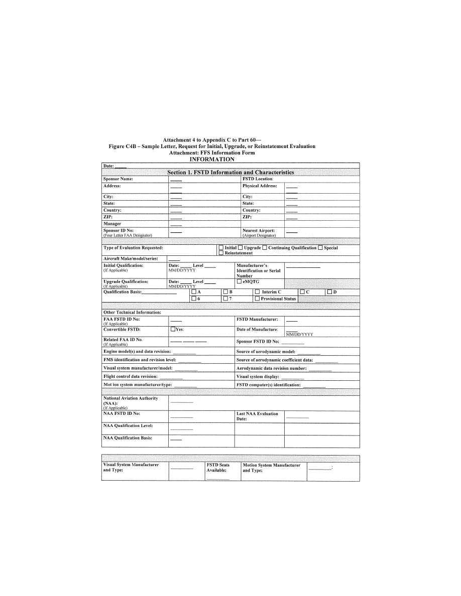
369
Federal Aviation Administration, DOT
Pt. 60, App. C
VerDate Sep<11>2014
14:00 Mar 14, 2024
Jkt 262047
PO 00000
Frm 00379
Fmt 8010
Sfmt 8006
Q:\14\14V2.TXT
PC31
ER09MY08.041</GPH>
aworley on LAPBH6H6L3 with DISTILLER

370
14 CFR Ch. I (1–1–24 Edition)
Pt. 60, App. C
VerDate Sep<11>2014
14:00 Mar 14, 2024
Jkt 262047
PO 00000
Frm 00380
Fmt 8010
Sfmt 8006
Q:\14\14V2.TXT
PC31
ER09MY08.042</GPH>
aworley on LAPBH6H6L3 with DISTILLER
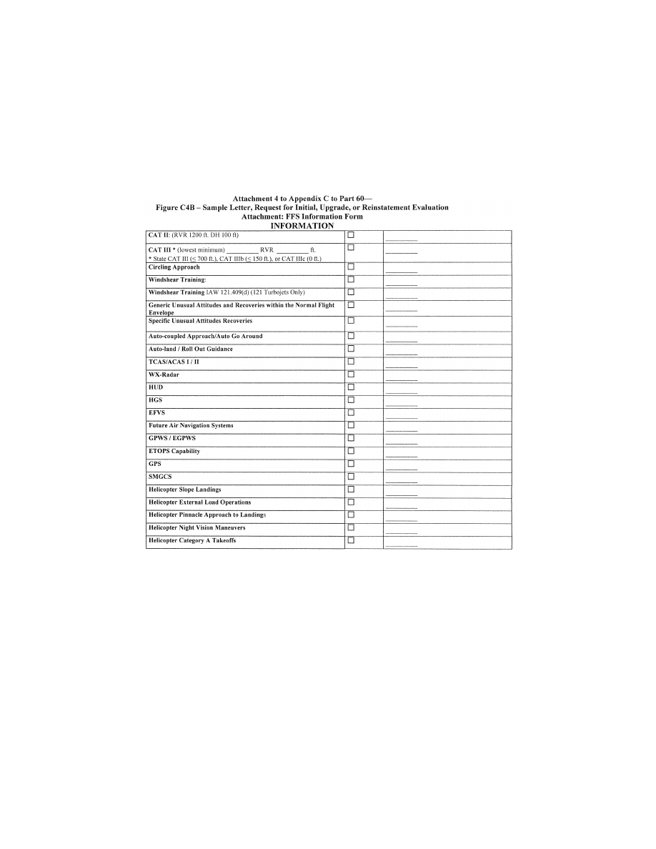
371
Federal Aviation Administration, DOT
Pt. 60, App. C
A
TTACHMENT
4
TO
A
PPENDIX
C
TO
P
ART
60—
F
IGURE
C4C—S
AMPLE
L
ETTER OF
C
OMPLIANCE
I
NFORMATION
VerDate Sep<11>2014
14:00 Mar 14, 2024
Jkt 262047
PO 00000
Frm 00381
Fmt 8010
Sfmt 8002
Q:\14\14V2.TXT
PC31
ER09MY08.043</GPH>
aworley on LAPBH6H6L3 with DISTILLER

372
14 CFR Ch. I (1–1–24 Edition)
Pt. 60, App. C
A
TTACHMENT
4
TO
A
PPENDIX
C
TO
P
ART
60—
F
IGURE
C4D—S
AMPLE
Q
UALIFICATION
T
EST
G
UIDE
C
OVER
P
AGE
I
NFORMATION
VerDate Sep<11>2014
14:00 Mar 14, 2024
Jkt 262047
PO 00000
Frm 00382
Fmt 8010
Sfmt 8002
Q:\14\14V2.TXT
PC31
ER09DE22.114</GPH>
aworley on LAPBH6H6L3 with DISTILLER

373
Federal Aviation Administration, DOT
Pt. 60, App. C
A
TTACHMENT
4
TO
A
PPENDIX
C
TO
P
ART
60—
F
IGURE
C4E—S
AMPLE
S
TATEMENT OF
Q
UALI
-
FICATION
—C
ERTIFICATE
I
NFORMATION
VerDate Sep<11>2014
14:00 Mar 14, 2024
Jkt 262047
PO 00000
Frm 00383
Fmt 8010
Sfmt 8002
Q:\14\14V2.TXT
PC31
ER09DE22.115</GPH>
aworley on LAPBH6H6L3 with DISTILLER
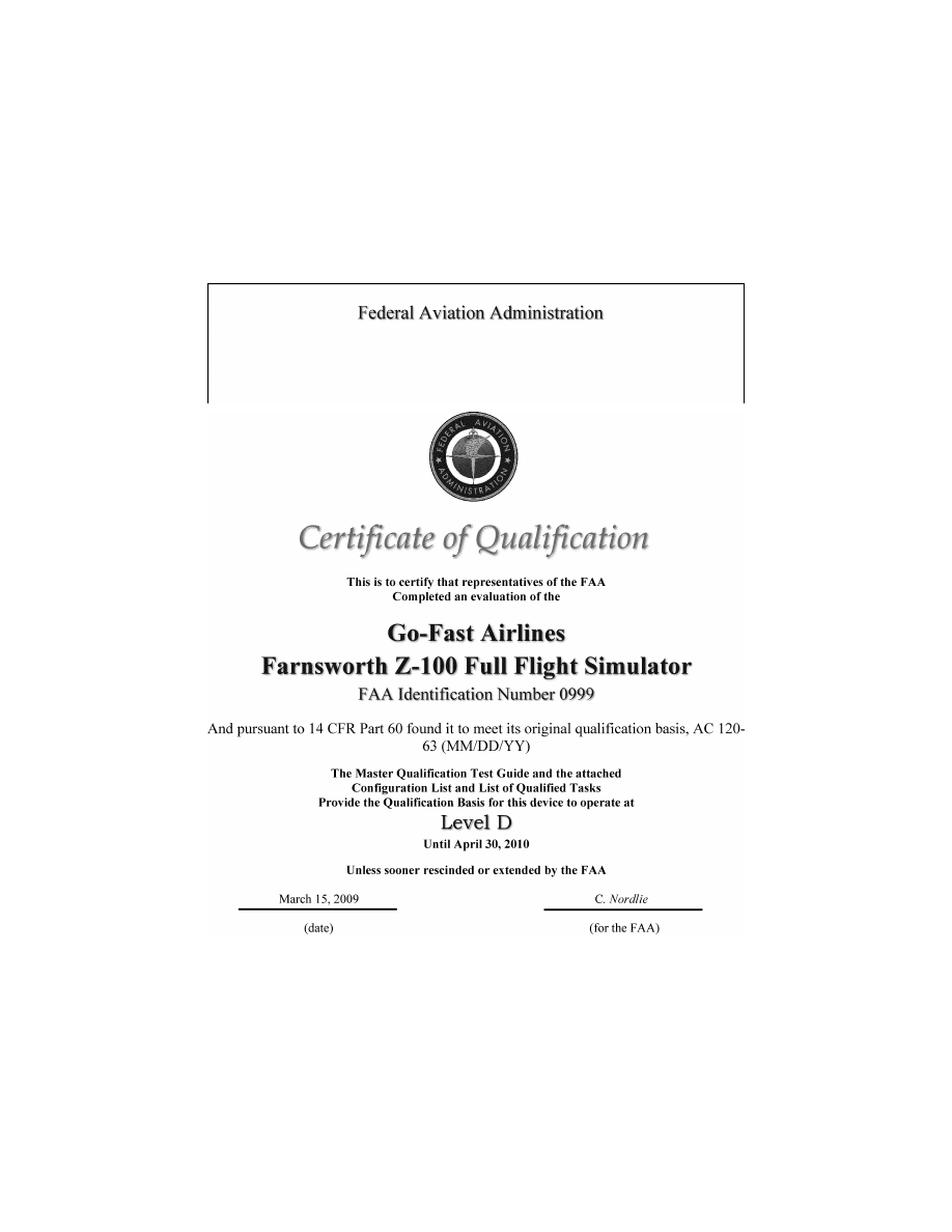
374
14 CFR Ch. I (1–1–24 Edition)
Pt. 60, App. C
VerDate Sep<11>2014
14:00 Mar 14, 2024
Jkt 262047
PO 00000
Frm 00384
Fmt 8010
Sfmt 8006
Q:\14\14V2.TXT
PC31
ER09DE22.116</GPH>
ER09DE22.129</GPH>
aworley on LAPBH6H6L3 with DISTILLER
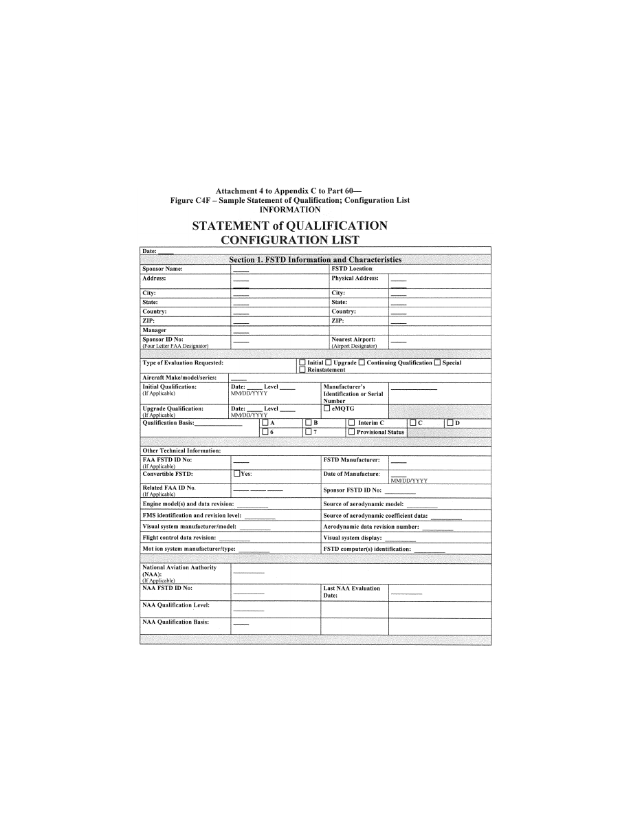
375
Federal Aviation Administration, DOT
Pt. 60, App. C
VerDate Sep<11>2014
14:00 Mar 14, 2024
Jkt 262047
PO 00000
Frm 00385
Fmt 8010
Sfmt 8006
Q:\14\14V2.TXT
PC31
ER09MY08.047</GPH>
aworley on LAPBH6H6L3 with DISTILLER

376
14 CFR Ch. I (1–1–24 Edition)
Pt. 60, App. C
VerDate Sep<11>2014
14:00 Mar 14, 2024
Jkt 262047
PO 00000
Frm 00386
Fmt 8010
Sfmt 8006
Q:\14\14V2.TXT
PC31
ER09MY08.048</GPH>
aworley on LAPBH6H6L3 with DISTILLER

377
Federal Aviation Administration, DOT
Pt. 60, App. C
VerDate Sep<11>2014
14:00 Mar 14, 2024
Jkt 262047
PO 00000
Frm 00387
Fmt 8010
Sfmt 8006
Q:\14\14V2.TXT
PC31
ER09MY08.049</GPH>
aworley on LAPBH6H6L3 with DISTILLER

378
14 CFR Ch. I (1–1–24 Edition)
Pt. 60, App. C
A
TTACHMENT
4
TO
A
PPENDIX
C
TO
P
ART
60—F
IGURE
C4H [R
ESERVED
]
VerDate Sep<11>2014
14:00 Mar 14, 2024
Jkt 262047
PO 00000
Frm 00388
Fmt 8010
Sfmt 8026
Q:\14\14V2.TXT
PC31
ER09MY08.050</GPH>
aworley on LAPBH6H6L3 with DISTILLER
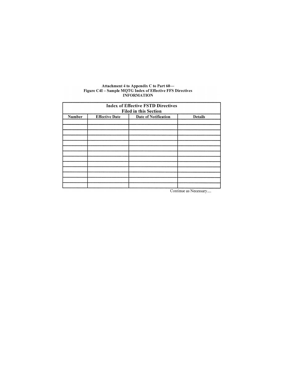
379
Federal Aviation Administration, DOT
Pt. 60, App. C
A
TTACHMENT
5
TO
A
PPENDIX
C
TO
P
ART
60—
FSTD DIRECTIVES APPLICABLE TO
HELICOPTER FFS
S
F
LIGHT
S
IMULATION
T
RAINING
D
EVICE
(FSTD)
D
IRECTIVE
FSTD Directive 1. Applicable to all FFSs,
regardless of the original qualification basis
and qualification date (original or upgrade),
having Class II or Class III airport models
available.
Agency: Federal Aviation Administration
(FAA), DOT
Action: This is a retroactive requirement to
have all Class II or Class III airport models
meet current requirements.
llllllllllllllllllllllll
Summary: Notwithstanding the authoriza-
tion listed in paragraph 13b in Appendices A
and C of this part, this FSTD Directive re-
quires each certificate holder to ensure that
by May 30, 2009, except for the airport
model(s) used to qualify the simulator at the
designated level, each airport model used by
the certificate holder’s instructors or eval-
uators for training, checking, or testing
under this chapter in an FFS, meets the defi-
nition of a Class II or Class III airport model
as defined in 14CFR part 60. The completion
of this requirement will not require a report,
and the method used for keeping instructors
and evaluators apprised of the airport mod-
els that meet Class II or Class III require-
ments on any given simulator is at the op-
tion of the certificate holder whose employ-
ees are using the FFS, but the method used
must be available for review by the TPAA
for that certificate holder.
Dates: FSTD Directive 1 becomes effective
on May 30, 2008.
S
PECIFIC
R
EQUIREMENTS
:
1. Part 60 requires that each FSTD be:
a. Sponsored by a person holding or apply-
ing for an FAA operating certificate under
Part 119, Part 141, or Part 142, or holding or
applying for an FAA-approved training pro-
gram under Part 63, Appendix C, for flight
engineers, and
b. Evaluated and issued an SOQ for a spe-
cific FSTD level.
2. FFSs also require the installation of a
visual system that is capable of providing an
out-of-the-flight-deck view of airport mod-
els. However, historically these airport mod-
els were not routinely evaluated or required
to meet any standardized criteria. This has
led to qualified simulators containing air-
port models being used to meet FAA-ap-
proved training, testing, or checking require-
ments with potentially incorrect or inappro-
priate visual references.
3. To prevent this from occurring in the fu-
ture, by May 30, 2009, except for the airport
model(s) used to qualify the simulator at the
designated level, each certificate holder
must assure that each airport model used for
training, testing, or checking under this
VerDate Sep<11>2014
14:00 Mar 14, 2024
Jkt 262047
PO 00000
Frm 00389
Fmt 8010
Sfmt 8002
Q:\14\14V2.TXT
PC31
ER09MY08.052</GPH>
aworley on LAPBH6H6L3 with DISTILLER

380
14 CFR Ch. I (1–1–24 Edition)
Pt. 60, App. D
chapter in a qualified FFS meets the defini-
tion of a Class II or Class III airport model
as defined in Appendix F of this part.
4. These references describe the require-
ments for visual scene management and the
minimum distances from which runway or
landing area features must be visible for all
levels of simulator. The visual scene or air-
port model must provide, for each ‘‘in-use
runway’’ or ‘‘in-use landing area,’’ runway or
landing area surface and markings, runway
or landing area lighting, taxiway surface and
markings, and taxiway lighting. Additional
requirements include correlation of the vis-
ual scenes or airport models with other as-
pects of the airport environment, correlation
of the aircraft and associated equipment,
scene quality assessment features, and the
extent to which the instructor is able to ex-
ercise control of these scenes or models.
5. For circling approaches, all require-
ments of this section apply to the runway
used for the initial approach and to the run-
way of intended landing.
6. The details in these scenes or models
must be developed using airport pictures,
construction drawings and maps, or other
similar data, or be developed in accordance
with published regulatory material. How-
ever, FSTD Directive 1 does not require that
airport models contain details that are be-
yond the initially designed capability of the
visual system, as currently qualified. The
recognized limitations to visual systems are
as follows:
a. Visual systems not required to have run-
way numbers as a part of the specific runway
marking requirements are:
(1) Link NVS and DNVS.
(2) Novoview 2500 and 6000.
(3) FlightSafety VITAL series up to, and
including, VITAL III, but not beyond.
(4) Redifusion SP1, SP1T, and SP2.
b. Visual systems required to display run-
way numbers only for LOFT scenes are:
(1) FlightSafety VITAL IV.
(2) Redifusion SP3 and SP3T.
(3) Link-Miles Image II.
c. Visual systems not required to have ac-
curate taxiway edge lighting are:
(1) Redifusion SP1.
(2) FlightSafety Vital IV.
(3) Link-Miles Image II and Image IIT
(4) XKD displays (even though the XKD
image generator is capable of generating
blue colored lights, the display cannot ac-
commodate that color).
7. A copy of this Directive must be filed in
the MQTG in the designated FSTD Directive
Section, and its inclusion must be annotated
on the Index of Effective FSTD Directives
chart. See Attachment 4, Appendices A
through D of this part for a sample MQTG
Index of Effective FSTD Directives chart.
[Doc. No. FAA–2002–12461, 73 FR 26490, May 9,
2008, as amended by Docket FAA–2018–0119,
Amdt. 60–5, 83 FR 9170, Mar. 5, 2018; Amdt. 60–
6, 83 FR 30275, June 27, 2018; Docket No. FAA–
2022–1355; Amdt. No. 60–7; 87 FR 75822, Dec. 9,
2022]
E
DITORIAL
N
OTE
: At 87 FR 75822, Dec. 9,
2022, appendix C to part 60 was amended in
the introductory ‘‘Begin Information’’ text,
by removing the word ‘‘NSPM’’ and adding
in its place the words ‘‘Flight Standards
Service’’ in the first sentence; however this
amendment could not be incorporated due to
inaccurate amendatory instruction.
A
PPENDIX
D
TO
P
ART
60—Q
UALIFICATION
P
ERFORMANCE
S
TANDARDS FOR
H
EL
-
ICOPTER
F
LIGHT
T
RAINING
D
EVICES
llllllllllllllllllllllll
B
EGIN
I
NFORMATION
This appendix establishes the standards for
Helicopter Flight Training Device (FTD)
evaluation and qualification at Level 4,
Level 5, Level 6, or Level 7. The Flight
Standards Service is responsible for the de-
velopment, application, and implementation
of the standards contained within this ap-
pendix. The procedures and criteria specified
in this appendix will be used by the respon-
sible Flight Standards office when con-
ducting helicopter FTD evaluations.
T
ABLE OF
C
ONTENTS
1. Introduction.
2. Applicability (§§ 60.1, 60.2).
3. Definitions (§ 60.3).
4. Qualification Performance Standards
(§ 60.4).
5. Quality Management System (§ 60.5).
6. Sponsor Qualification Requirements
(§ 60.7).
7. Additional Responsibilities of the Spon-
sor (§ 60.9).
8. FTD Use (§ 60.11).
9. FTD Objective Data Requirements
(§ 60.13).
10. Special Equipment and Personnel Re-
quirements for Qualification of the FTD
(§ 60.14).
11. Initial (and Upgrade) Qualification Re-
quirements (§ 60.15).
12. Additional Qualifications for Currently
Qualified FTDs (§ 60.16).
13. Previously Qualified FTDs (§ 60.17).
14. Inspection, Continuing Qualification
Evaluation, and Maintenance Requirements
(§ 60.19).
15. Logging FTD Discrepancies (§ 60.20).
16. Interim Qualification of FTDs for New
Helicopter Types or Models (§ 60.21).
17. Modifications to FTDs (§ 60.23).
VerDate Sep<11>2014
14:00 Mar 14, 2024
Jkt 262047
PO 00000
Frm 00390
Fmt 8010
Sfmt 8002
Q:\14\14V2.TXT
PC31
aworley on LAPBH6H6L3 with DISTILLER

381
Federal Aviation Administration, DOT
Pt. 60, App. D
18. Operations with Missing, Malfunc-
tioning, or Inoperative Components (§ 60.25).
19. Automatic Loss of Qualification and
Procedures for Restoration of Qualification
(§ 60.27).
20. Other Losses of Qualification and Pro-
cedures for Restoration of Qualification
(§ 60.29).
21. Recordkeeping and Reporting (§ 60.31).
22. Applications, Logbooks, Reports, and
Records: Fraud, Falsification, or Incorrect
Statements (§ 60.33).
23. [Reserved]
24. Levels of FTD.
25. FTD Qualification on the Basis of a Bi-
lateral Aviation Safety Agreement (BASA)
(§ 60.37).
Attachment 1 to Appendix D to Part 60—
General FTD Requirements.
Attachment 2 to Appendix D to Part 60—
Flight Training Device (FTD) Objective
Tests.
Attachment 3 to Appendix D to Part 60—
Flight Training Device (FTD) Subjective
Evaluation.
Attachment 4 to Appendix D to Part 60—
Sample Documents.
E
ND
I
NFORMATION
llllllllllllllllllllllll
1. I
NTRODUCTION
llllllllllllllllllllllll
B
EGIN
I
NFORMATION
a. This appendix contains background in-
formation as well as regulatory and inform-
ative material as described later in this sec-
tion. To assist the reader in determining
what areas are required and what areas are
permissive, the text in this appendix is di-
vided into two sections: ‘‘QPS Require-
ments’’ and ‘‘Information.’’ The QPS Re-
quirements sections contain details regard-
ing compliance with the part 60 rule lan-
guage. These details are regulatory, but are
found only in this appendix. The Information
sections contain material that is advisory in
nature, and designed to give the user general
information about the regulation.
b. [Reserved]
c. The responsible Flight Standards office
encourages the use of electronic media for
all communication, including any record, re-
port, request, test, or statement required by
this appendix. The electronic media used
must have adequate security provisions and
be acceptable to the responsible Flight
Standards office.
d. Related Reading References.
(1) 14 CFR part 60.
(2) 14 CFR part 61.
(3) 14 CFR part 63.
(4) 14 CFR part 119.
(5) 14 CFR part 121.
(6) 14 CFR part 125.
(7) 14 CFR part 135.
(8) 14 CFR part 141.
(9) 14 CFR part 142.
(10) AC 120–28, as amended, Criteria for Ap-
proval of Category III Landing Weather
Minima.
(11) AC 120–29, as amended, Criteria for Ap-
proving Category I and Category II Landing
Minima for part 121 operators.
(12) AC 120–35, as amended, Flightcrew
Member Line Operational Simulations: Line-
Oriented Flight Training, Special Purpose
Operational Training, Line Operational
Evaluation.
(13) AC 120–41, as amended, Criteria for
Operational Approval of Airborne Wind
Shear Alerting and Flight Guidance Sys-
tems.
(14) AC 120–57, as amended, Surface Move-
ment Guidance and Control System
(SMGCS).
(15) AC 120–63, as amended, Helicopter Sim-
ulator Qualification.
(16) AC 150/5300–13, as amended, Airport De-
sign.
(17) AC 150/5340–1, as amended, Standards
for Airport Markings.
(18) AC 150/5340–4, as amended, Installation
Details for Runway Centerline Touchdown
Zone Lighting Systems.
(19) AC 150/5390–2, as amended, Heliport De-
sign.
(20) AC 150/5340–19, as amended, Taxiway
Centerline Lighting System.
(21) AC 150/5340–24, as amended, Runway
and Taxiway Edge Lighting System.
(22) AC 150/5345–28, as amended, Precision
Approach Path Indicator (PAPI) Systems.
(23) International Air Transport Associa-
tion document, ‘‘Flight Simulator Design
and Performance Data Requirements,’’ as
amended.
(24) AC 29–2, as amended, Flight Test Guide
for Certification of Transport Category
Rotorcraft.
(25) AC 27–1, as amended, Flight Test Guide
for Certification of Normal Category Rotor-
craft.
(26) International Civil Aviation Organiza-
tion (ICAO) Manual of Criteria for the Quali-
fication of Flight Simulators, as amended.
(27) Airplane Flight Simulator Evaluation
Handbook, Volume I, as amended and Vol-
ume II, as amended, The Royal Aeronautical
Society, London, UK.
(28) FAA Airman Certification Standards
and Practical Test Standards for Airline
Transport Pilot, Type Ratings, Commercial
Pilot, and Instrument Ratings.
(29) The FAA Aeronautical Information
Manual (AIM). An electronic version of the
AIM is on the Internet at
http://www.faa.gov/
atpubs.
(30) Aeronautical Radio, Inc. (ARINC) doc-
ument number 436,
Guidelines For Electronic
Qualification Test Guide (as amended).
VerDate Sep<11>2014
14:00 Mar 14, 2024
Jkt 262047
PO 00000
Frm 00391
Fmt 8010
Sfmt 8002
Q:\14\14V2.TXT
PC31
aworley on LAPBH6H6L3 with DISTILLER

382
14 CFR Ch. I (1–1–24 Edition)
Pt. 60, App. D
(31) Aeronautical Radio, Inc. (ARINC) doc-
ument 610,
Guidance for Design and Integra-
tion of Aircraft Avionics Equipment in Simula-
tors (as amended).
E
ND
I
NFORMATION
llllllllllllllllllllllll
2. A
PPLICABILITY
(§ 60.1
AND
60.2)
llllllllllllllllllllllll
B
EGIN
I
NFORMATION
No additional regulatory or informational
material applies to § 60.1, Applicability, or to
§ 60.2, Applicability of sponsor rules to person
who are not sponsors and who are engaged in
certain unauthorized activities.
E
ND
I
NFORMATION
llllllllllllllllllllllll
3. D
EFINITIONS
(§ 60.3)
llllllllllllllllllllllll
B
EGIN
I
NFORMATION
See Appendix F of this part for a list of
definitions and abbreviations from part 1,
part 60, and the QPS appendices of part 60.
E
ND
I
NFORMATION
llllllllllllllllllllllll
4. Q
UALIFICATION
P
ERFORMANCE
S
TANDARDS
(§ 60.4)
B
EGIN
I
NFORMATION
No additional regulatory or informational
material applies to § 60.4, Qualification Per-
formance Standards.
E
ND
I
NFORMATION
llllllllllllllllllllllll
5. Q
UALITY
M
ANAGEMENT
S
YSTEM
(§ 60.5)
llllllllllllllllllllllll
B
EGIN
I
NFORMATION
Additional regulatory material and infor-
mational material regarding Quality Man-
agement Systems for FTDs may be found in
Appendix E of this part.
E
ND
I
NFORMATION
llllllllllllllllllllllll
6. S
PONSOR
Q
UALIFICATION
R
EQUIREMENTS
(§ 60.7)
llllllllllllllllllllllll
B
EGIN
I
NFORMATION
a. The intent of the language in § 60.7(b) is
to have a specific FTD, identified by the
sponsor, used at least once in an FAA-ap-
proved flight training program for the heli-
copter simulated during the 12-month period
described. The identification of the specific
FTD may change from one 12-month period
to the next 12-month period as long as that
sponsor sponsors and uses at least one FTD
at least once during the prescribed period.
There is no minimum number of hours or
minimum FTD periods required.
b. The following examples describe accept-
able operational practices:
(1) Example One.
(a) A sponsor is sponsoring a single, spe-
cific FTD for its own use, in its own facility
or elsewhere—this single FTD forms the
basis for the sponsorship. The sponsor uses
that FTD at least once in each 12-month pe-
riod in that sponsor’s FAA-approved flight
training program for the helicopter simu-
lated. This 12-month period is established ac-
cording to the following schedule:
(i) If the FTD was qualified prior to May
30, 2008, the 12-month period begins on the
date of the first continuing qualification
evaluation conducted in accordance with
§ 60.19 after May 30, 2008, and continues for
each subsequent 12-month period;
(ii) A device qualified on or after May 30,
2008, will be required to undergo an initial or
upgrade evaluation in accordance with
§ 60.15. Once the initial or upgrade evaluation
is complete, the first continuing qualifica-
tion evaluation will be conducted within 6
months. The 12 month continuing qualifica-
tion evaluation cycle begins on that date and
continues for each subsequent 12-month pe-
riod.
(b) There is no minimum number of hours
of FTD use required.
(c) The identification of the specific FTD
may change from one 12-month period to the
next 12-month period as long as that sponsor
sponsors and uses at least one FTD at least
once during the prescribed period.
(2) Example Two.
(a) A sponsor sponsors an additional num-
ber of FTDs, in its facility or elsewhere.
Each additionally sponsored FTD must be—
(i) Used by the sponsor in the sponsor’s
FAA-approved flight training program for
the helicopter simulated (as described in
§ 60.7(d)(1)); or
(ii) Used by another FAA certificate holder
in that other certificate holder’s FAA-ap-
proved flight training program for the heli-
copter simulated (as described in § 60.7(d)(1)).
This 12-month period is established in the
same manner as in example one; or
(iii) Provided a statement each year from a
qualified pilot, (after having flown the heli-
copter not the subject FTD or another FTD,
during the preceding 12-month period) stat-
ing that the subject FTD’s performance and
handling qualities represent the helicopter
(as described in § 60.7(d)(2)). This statement is
provided at least once in each 12-month pe-
riod established in the same manner as in ex-
ample one.
VerDate Sep<11>2014
14:00 Mar 14, 2024
Jkt 262047
PO 00000
Frm 00392
Fmt 8010
Sfmt 8002
Q:\14\14V2.TXT
PC31
aworley on LAPBH6H6L3 with DISTILLER

383
Federal Aviation Administration, DOT
Pt. 60, App. D
(b) There is no minimum number of hours
of FTD use required.
(3) Example Three.
(a) A sponsor in New York (in this exam-
ple, a Part 142 certificate holder) establishes
‘‘satellite’’ training centers in Chicago and
Moscow.
(b) The satellite function means that the
Chicago and Moscow centers must operate
under the New York center’s certificate (in
accordance with all of the New York center’s
practices, procedures, and policies; e.g., in-
structor and/or technician training/checking
requirements, record keeping, QMS pro-
gram).
(c) All of the FTDs in the Chicago and Mos-
cow centers could be dry-leased (i.e., the cer-
tificate holder does not have and use FAA-
approved flight training programs for the
FTDs in the Chicago and Moscow centers)
because—
(i) Each FTD in the Chicago center and
each FTD in the Moscow center is used at
least once each 12-month period by another
FAA certificate holder in that other certifi-
cate holder’s FAA-approved flight training
program for the helicopter (as described in
§ 60.7(d)(1)); or
(ii) A statement is obtained from a quali-
fied pilot (having flown the helicopter, not
the subject FTD or another FTD during the
preceding 12-month period) stating that the
performance and handling qualities of each
FTD in the Chicago and Moscow centers rep-
resents the helicopter (as described in
§ 60.7(d)(2)).
E
ND
I
NFORMATION
llllllllllllllllllllllll
7. A
DDITIONAL
R
ESPONSIBILITIES OF THE
S
PONSOR
(§ 60.9)
llllllllllllllllllllllll
B
EGIN
I
NFORMATION
The phrase ‘‘as soon as practicable’’ in
§ 60.9(a) means without unnecessarily dis-
rupting or delaying beyond a reasonable
time the training, evaluation, or experience
being conducted in the FTD.
E
ND
I
NFORMATION
llllllllllllllllllllllll
8. FTD U
SE
(§ 60.11).
llllllllllllllllllllllll
B
EGIN
I
NFORMATION
No additional regulatory or informational
material applies to § 60.11, FTD Use.
E
ND
I
NFORMATION
llllllllllllllllllllllll
9. FTD O
BJECTIVE
D
ATA
R
EQUIREMENTS
(§ 60.13)
llllllllllllllllllllllll
B
EGIN
QPS R
EQUIREMENTS
a. Flight test data used to validate FTD
performance and handling qualities must
have been gathered in accordance with a
flight test program containing the following:
(1) A flight test plan consisting of:
(a) The maneuvers and procedures required
for aircraft certification and simulation pro-
gramming and validation.
(b) For each maneuver or procedure—
(i) The procedures and control input the
flight test pilot and/or engineer used.
(ii) The atmospheric and environmental
conditions.
(iii) The initial flight conditions.
(iv) The helicopter configuration, includ-
ing weight and center of gravity.
(v) The data to be gathered.
(vi) All other information necessary to
recreate the flight test conditions in the
FTD.
(2) Appropriately qualified flight test per-
sonnel.
(3) Appropriate and sufficient data acquisi-
tion equipment or system(s), including ap-
propriate data reduction and analysis meth-
ods and techniques, acceptable to the FAA’s
Aircraft Certification Service.
b. The data, regardless of source, must be
presented:
(1) In a format that supports the FTD vali-
dation process;
(2) In a manner that is clearly readable and
annotated correctly and completely;
(3) With resolution sufficient to determine
compliance with the tolerances set forth in
Attachment 2, Table D2A Appendix D;
(4) With any necessary guidance informa-
tion provided; and
(5) Without alteration, adjustments, or
bias. Data may be corrected to address
known data calibration errors provided that
an explanation of the methods used to cor-
rect the errors appears in the QTG. The cor-
rected data may be re-scaled, digitized, or
otherwise manipulated to fit the desired
presentation
c. After completion of any additional flight
test, a flight test report must be submitted
in support of the validation data. The report
must contain sufficient data and rationale to
support qualification of the FTD at the level
requested.
d. As required by § 60.13(f), the sponsor
must notify the responsible Flight Standards
office when it becomes aware that an addi-
tion to or a revision of the flight related
data or helicopter systems related data is
available if this data is used to program and
operate a qualified FTD. The data referred to
in this sub-section is data used to validate
the performance, handling qualities, or other
VerDate Sep<11>2014
14:00 Mar 14, 2024
Jkt 262047
PO 00000
Frm 00393
Fmt 8010
Sfmt 8002
Q:\14\14V2.TXT
PC31
aworley on LAPBH6H6L3 with DISTILLER

384
14 CFR Ch. I (1–1–24 Edition)
Pt. 60, App. D
characteristics of the aircraft, including
data related to any relevant changes occur-
ring after the type certification is issued.
The sponsor must—
(1) Within 10 calendar days, notify the re-
sponsible Flight Standards office of the ex-
istence of this data; and
(a) Within 45 calendar days, notify the re-
sponsible Flight Standards office of—
(b) The schedule to incorporate this data
into the FTD; or
(c) The reason for not incorporating this
data into the FTD.
e. In those cases where the objective test
results authorize a ‘‘snapshot test’’ or a ‘‘se-
ries of snapshot tests’’ results in lieu of a
time-history result, the sponsor or other
data provider must ensure that a steady
state condition exists at the instant of time
captured by the ‘‘snapshot.’’ The steady
state condition must exist from 4 seconds
prior to, through 1 second following, the in-
stant of time captured by the snap shot.
E
ND
QPS R
EQUIREMENTS
llllllllllllllllllllllll
B
EGIN
I
NFORMATION
f. The FTD sponsor is encouraged to main-
tain a liaison with the manufacturer of the
aircraft being simulated (or with the holder
of the aircraft type certificate for the air-
craft being simulated if the manufacturer is
no longer in business), and if appropriate,
with the person having supplied the aircraft
data package for the FTD in order to facili-
tate the notification described in this para-
graph.
g. It is the intent of the responsible Flight
Standards office that for new aircraft enter-
ing service, at a point well in advance of
preparation of the QTG, the sponsor should
submit to the responsible Flight Standards
office for approval, a descriptive document
(see Appendix C of this part, Table C2D,
Sample Validation Data Roadmap for Heli-
copters) containing the plan for acquiring
the validation data, including data sources.
This document should clearly identify
sources of data for all required tests, a de-
scription of the validity of these data for a
specific engine type and thrust rating con-
figuration, and the revision levels of all avi-
onics affecting the performance or flying
qualities of the aircraft. Additionally, this
document should provide other information
such as the rationale or explanation for
cases where data or data parameters are
missing, instances where engineering sim-
ulation data are used, or where flight test
methods require further explanations. It
should also provide a brief narrative describ-
ing the cause and effect of any deviation
from data requirements. The aircraft manu-
facturer may provide this document.
h. There is no requirement for any flight
test data supplier to submit a flight test
plan or program prior to gathering flight
test data. However, the responsible Flight
Standards office notes that inexperienced
data gatherers often provide data that is ir-
relevant, improperly marked, or lacking ade-
quate justification for selection. Other prob-
lems include inadequate information regard-
ing initial conditions or test maneuvers. The
responsible Flight Standards office has been
forced to refuse these data submissions as
validation data for an FTD evaluation. For
this reason the responsible Flight Standards
office recommends that any data supplier
not previously experienced in this area re-
view the data necessary for programming
and for validating the performance of the
FTD and discuss the flight test plan antici-
pated for acquiring such data with the re-
sponsible Flight Standards office well in ad-
vance of commencing the flight tests.
i. The responsible Flight Standards office
will consider, on a case-by-case basis, wheth-
er to approve supplemental validation data
derived from flight data recording systems
such as a Quick Access Recorder or Flight
Data Recorder.
E
ND
I
NFORMATION
llllllllllllllllllllllll
10. S
PECIAL
E
QUIPMENT AND
P
ERSONNEL
R
E
-
QUIREMENTS FOR
Q
UALIFICATION OF THE
FTD
(§ 60.14).
llllllllllllllllllllllll
B
EGIN
I
NFORMATION
a. In the event that the responsible Flight
Standards office determines that special
equipment or specifically qualified persons
will be required to conduct an evaluation,
the responsible Flight Standards office will
make every attempt to notify the sponsor at
least one (1) week, but in no case less than 72
hours, in advance of the evaluation. Exam-
ples of special equipment include flight con-
trol measurement devices, accelerometers,
or oscilloscopes. Examples of specially quali-
fied personnel include individuals specifi-
cally qualified to install or use any special
equipment when its use is required.
b. Examples of a special evaluation include
an evaluation conducted after an FTD is
moved; at the request of the TPAA; or as a
result of comments received from users of
the FTD that raise questions about the con-
tinued qualification or use of the FTD.
E
ND
I
NFORMATION
llllllllllllllllllllllll
11. I
NITIAL
(
AND
U
PGRADE
) Q
UALIFICATION
R
EQUIREMENTS
(§ 60.15).
llllllllllllllllllllllll
VerDate Sep<11>2014
14:00 Mar 14, 2024
Jkt 262047
PO 00000
Frm 00394
Fmt 8010
Sfmt 8002
Q:\14\14V2.TXT
PC31
aworley on LAPBH6H6L3 with DISTILLER

385
Federal Aviation Administration, DOT
Pt. 60, App. D
B
EGIN
QPS R
EQUIREMENT
a. In order to be qualified at a particular
qualification level, the FTD must:
(1) Meet the general requirements listed in
Attachment 1 of this appendix.
(2) Meet the objective testing requirements
listed in Attachment 2 of this appendix
(Level 4 FTDs do not require objective tests).
(3) Satisfactorily accomplish the subjec-
tive tests listed in Attachment 3 of this ap-
pendix.
b. The request described in § 60.15(a) must
include all of the following:
(1) A statement that the FTD meets all of
the applicable provisions of this part and all
applicable provisions of the QPS.
(2) A confirmation that the sponsor will
forward to the responsible Flight Standards
office the statement described in § 60.15(b) in
such time as to be received no later than 5
business days prior to the scheduled evalua-
tion and may be forwarded to the responsible
Flight Standards office via traditional or
electronic means.
(3) Except for a Level 4 FTD, a QTG, ac-
ceptable to the responsible Flight Standards
office, that includes all of the following:
(a) Objective data obtained from aircraft
testing or another approved source.
(b) Correlating objective test results ob-
tained from the performance of the FTD as
prescribed in the appropriate QPS.
(c) The result of FTD subjective tests pre-
scribed in the appropriate QPS.
(d) A description of the equipment nec-
essary to perform the evaluation for initial
qualification and the continuing qualifica-
tion evaluations.
c. The QTG described in paragraph a(3) of
this section must provide the documented
proof of compliance with the FTD objective
tests in Attachment 2, Table D2A of this ap-
pendix.
d. The QTG is prepared and submitted by
the sponsor, or the sponsor’s agent on behalf
of the sponsor, to the responsible Flight
Standards office for review and approval, and
must include, for each objective test:
(1) Parameters, tolerances, and flight con-
ditions.
(2) Pertinent and complete instructions for
conducting automatic and manual tests.
(3) A means of comparing the FTD test re-
sults to the objective data.
(4) Any other information as necessary to
assist in the evaluation of the test results.
(5) Other information appropriate to the
qualification level of the FTD.
e. The QTG described in paragraphs (a)(3)
and (b) of this section, must include the fol-
lowing:
(1) A QTG cover page with sponsor and
FAA approval signature blocks (see Attach-
ment 4, Figure D4C, of this appendix, for a
sample QTG cover page).
(2) A continuing qualification evaluation
requirements page. This page will be used by
the responsible Flight Standards office to es-
tablish and record the frequency with which
continuing qualification evaluations must be
conducted and any subsequent changes that
may be determined by the responsible Flight
Standards office in accordance with § 60.19.
See Attachment 4, Figure D4G, of this appen-
dix for a sample Continuing Qualification
Evaluation Requirements page.
(3) An FTD information page that provides
the information listed in this paragraph, if
applicable (see Attachment 4, Figure D4B, of
this appendix, for a sample FTD information
page). For convertible FTDs, the sponsor
must submit a separate page for each con-
figuration of the FTD.
(a) The sponsor’s FTD identification num-
ber or code.
(b) The helicopter model and series being
simulated.
(c) The aerodynamic data revision number
or reference.
(d) The source of the basic aerodynamic
model and the aerodynamic coefficient data
used to modify the basic model.
(e) The engine model(s) and its data revi-
sion number or reference.
(f) The flight control data revision number
or reference.
(g) The flight management system identi-
fication and revision level.
(h) The FTD model and manufacturer.
(i) The date of FTD manufacture.
(j) The FTD computer identification.
(k) The visual system model and manufac-
turer, including display type.
(l) The motion system type and manufac-
turer, including degrees of freedom.
(4) A Table of Contents.
(5) A log of revisions and a list of effective
pages.
(6) List of all relevant data references.
(7) A glossary of terms and symbols used
(including sign conventions and units).
(8) Statements of Compliance and Capa-
bility (SOC) with certain requirements.
(9) Recording procedures or equipment re-
quired to accomplish the objective tests.
(10) The following information for each ob-
jective test designated in Attachment 2 of
this appendix, as applicable to the qualifica-
tion level sought:
(a) Name of the test.
(b) Objective of the test.
(c) Initial conditions.
(d) Manual test procedures.
(e) Automatic test procedures (if applica-
ble).
(f) Method for evaluating FTD objective
test results.
(g) List of all relevant parameters driven
or constrained during the automatic test(s).
(h) List of all relevant parameters driven
or constrained during the manual test(s).
(i) Tolerances for relevant parameters.
VerDate Sep<11>2014
14:00 Mar 14, 2024
Jkt 262047
PO 00000
Frm 00395
Fmt 8010
Sfmt 8002
Q:\14\14V2.TXT
PC31
aworley on LAPBH6H6L3 with DISTILLER

386
14 CFR Ch. I (1–1–24 Edition)
Pt. 60, App. D
(j) Source of Validation Data (document
and page number).
(k) Copy of the Validation Data (if located
in a separate binder, a cross reference for the
identification and page number for pertinent
data location must be provided).
(l) FTD Objective Test Results as obtained
by the sponsor. Each test result must reflect
the date completed and must be clearly la-
beled as a product of the device being tested.
f. A convertible FTD is addressed as a sepa-
rate FTD for each model and series heli-
copter to which it will be converted and for
the FAA qualification level sought. The re-
sponsible Flight Standards office will con-
duct an evaluation for each configuration. If
a sponsor seeks qualification for two or more
models of a helicopter type using a convert-
ible FTD, the sponsor must provide a QTG
for each helicopter model, or a QTG for the
first helicopter model and a supplement to
that QTG for each additional helicopter
model. The responsible Flight Standards of-
fice will conduct evaluations for each heli-
copter model.
g. The form and manner of presentation of
objective test results in the QTG must in-
clude the following:
(1) The sponsor’s FTD test results must be
recorded in a manner acceptable to the re-
sponsible Flight Standards office, that al-
lows easy comparison of the FTD test results
to the validation data (e.g., use of a multi-
channel recorder, line printer, cross plotting,
overlays, transparencies).
(2) FTD results must be labeled using ter-
minology common to helicopter parameters
as opposed to computer software identifica-
tions.
(3) Validation data documents included in
a QTG may be photographically reduced only
if such reduction will not alter the graphic
scaling or cause difficulties in scale interpre-
tation or resolution.
(4) Scaling on graphical presentations
must provide the resolution necessary to
evaluate the parameters shown in Attach-
ment 2, Table D2A of this appendix.
(5) Tests involving time histories, data
sheets (or transparencies thereof) and FTD
test results must be clearly marked with ap-
propriate reference points to ensure an accu-
rate comparison between FTD and helicopter
with respect to time. Time histories recorded
via a line printer are to be clearly identified
for cross-plotting on the helicopter data.
Over-plots may not obscure the reference
data.
h. The sponsor may elect to complete the
QTG objective and subjective tests at the
manufacturer’s facility or at the sponsor’s
training facility. If the tests are conducted
at the manufacturer’s facility, the sponsor
must repeat at least one-third of the tests at
the sponsor’s training facility in order to
substantiate FTD performance. The QTG
must be clearly annotated to indicate when
and where each test was accomplished. Tests
conducted at the manufacturer’s facility and
at the sponsor’s training facility must be
conducted after the FTD is assembled with
systems and sub-systems functional and op-
erating in an interactive manner. The test
results must be submitted to the responsible
Flight Standards office.
i. The sponsor must maintain a copy of the
MQTG at the FTD location.
j. All FTDs for which the initial qualifica-
tion is conducted after May 30, 2014, must
have an electronic MQTG (eMQTG) including
all objective data obtained from helicopter
testing, or another approved source (refor-
matted or digitized), together with corre-
lating objective test results obtained from
the performance of the FTD (reformatted or
digitized) as prescribed in this appendix. The
eMQTG must also contain the general FTD
performance or demonstration results (refor-
matted or digitized) prescribed in this appen-
dix, and a description of the equipment nec-
essary to perform the initial qualification
evaluation and the continuing qualification
evaluations. The eMQTG must include the
original validation data used to validate
FTD performance and handling qualities in
either the original digitized format from the
data supplier or an electronic scan of the
original time-history plots that were pro-
vided by the data supplier. A copy of the
eMQTG must be provided to the responsible
Flight Standards office.
k. All other FTDs (not covered in subpara-
graph ‘‘j’’) must have an electronic copy of
the MQTG by and after May 30, 2014. An elec-
tronic copy of the MQTG must be provided to
the responsible Flight Standards office. This
may be provided by an electronic scan pre-
sented in a Portable Document File (PDF),
or similar format acceptable to the respon-
sible Flight Standards office.
l. During the initial (or upgrade) qualifica-
tion evaluation conducted by the responsible
Flight Standards office, the sponsor must
also provide a person knowledgeable about
the operation of the aircraft and the oper-
ation of the FTD.
E
ND
QPS R
EQUIREMENTS
llllllllllllllllllllllll
B
EGIN
I
NFORMATION
m. Only those FTDs that are sponsored by
a certificate holder as defined in Appendix F
of this part will be evaluated by the respon-
sible Flight Standards office. However, other
FTD evaluations may be conducted on a
case-by-case basis as the Administrator
deems appropriate, but only in accordance
with applicable agreements.
n. The responsible Flight Standards office
will conduct an evaluation for each configu-
ration, and each FTD must be evaluated as
completely as possible. To ensure a thorough
VerDate Sep<11>2014
14:00 Mar 14, 2024
Jkt 262047
PO 00000
Frm 00396
Fmt 8010
Sfmt 8002
Q:\14\14V2.TXT
PC31
aworley on LAPBH6H6L3 with DISTILLER

387
Federal Aviation Administration, DOT
Pt. 60, App. D
and uniform evaluation, each FTD is sub-
jected to the general FTD requirements in
Attachment 1 of this appendix, the objective
tests listed in Attachment 2 of this appendix,
and the subjective tests listed in Attachment
3 of this appendix. The evaluations described
herein will include, but not necessarily be
limited to the following:
(1) Helicopter responses, including longitu-
dinal and lateral-directional control re-
sponses (see Attachment 2 of this appendix).
(2) Performance in authorized portions of
the simulated helicopter’s operating enve-
lope, to include tasks evaluated by the re-
sponsible Flight Standards office in the
areas of surface operations, takeoff, climb,
cruise, descent, approach and landing, as
well as abnormal and emergency operations
(see Attachment 2 of this appendix).
(3) Control checks (see Attachment 1 and
Attachment 2 of this appendix).
(4) Flight deck configuration (see Attach-
ment 1 of this appendix).
(5) Pilot, flight engineer, and instructor
station functions checks (see Attachment 1
and Attachment 3 of this appendix).
(6) Helicopter systems and sub-systems (as
appropriate) as compared to the helicopter
simulated (see attachment 1 and attachment
3 of this appendix).
(7) FTD systems and sub-systems, includ-
ing force cueing (motion), visual, and aural
(sound) systems, as appropriate (see Attach-
ment 1 and Attachment 2 of this appendix).
(8) Certain additional requirements, de-
pending upon the qualification level sought,
including equipment or circumstances that
may become hazardous to the occupants. The
sponsor may be subject to Occupational
Safety and Health Administration require-
ments.
o. The responsible Flight Standards office
administers the objective and subjective
tests, which include an examination of func-
tions. The tests include a qualitative assess-
ment of the FTD by a pilot from the respon-
sible Flight Standards office. The evaluation
team leader may assign other qualified per-
sonnel to assist in accomplishing the func-
tions examination and/or the objective and
subjective tests performed during an evalua-
tion when required.
(1) Objective tests provide a basis for meas-
uring and evaluating FTD performance and
determining compliance with the require-
ments of this part.
(2) Subjective tests provide a basis for:
(a) Evaluating the capability of the FTD to
perform over a typical utilization period;
(b) Determining that the FTD satisfac-
torily simulates each required task;
(c) Verifying correct operation of the FTD
controls, instruments, and systems; and
(d) Demonstrating compliance with the re-
quirements of this part.
p. The tolerances for the test parameters
listed in Attachment 2 of this appendix re-
flect the range of tolerances acceptable to
the responsible Flight Standards office for
FTD validation and are not to be confused
with design tolerances specified for FTD
manufacture. In making decisions regarding
tests and test results, the responsible Flight
Standards office relies on the use of oper-
ational and engineering judgment in the ap-
plication of data (including consideration of
the way in which the flight test was flown
and way the data was gathered and applied),
data presentations, and the applicable toler-
ances for each test.
q. In addition to the scheduled continuing
qualification evaluation, each FTD is subject
to evaluations conducted by the responsible
Flight Standards office at any time without
prior notification to the sponsor. Such eval-
uations would be accomplished in a normal
manner (i.e., requiring exclusive use of the
FTD for the conduct of objective and subjec-
tive tests and an examination of functions) if
the FTD is not being used for flight crew-
member training, testing, or checking. How-
ever, if the FTD were being used, the evalua-
tion would be conducted in a non-exclusive
manner. This non-exclusive evaluation will
be conducted by the FTD evaluator accom-
panying the check airman, instructor, Air-
crew Program Designee (APD), or FAA in-
spector aboard the FTD along with the stu-
dent(s) and observing the operation of the
FTD during the training, testing, or check-
ing activities.
r. Problems with objective test results are
handled as follows:
(1) If a problem with an objective test re-
sult is detected by the evaluation team dur-
ing an evaluation, the test may be repeated
or the QTG may be amended.
(2) If it is determined that the results of an
objective test do not support the qualifica-
tion level requested but do support a lower
level, the responsible Flight Standards office
may qualify the FTD at a lower level.
s. After an FTD is successfully evaluated,
the responsible Flight Standards office
issues an SOQ to the sponsor. The respon-
sible Flight Standards office recommends
the FTD to the TPAA, who will approve the
FTD for use in a flight training program.
The SOQ will be issued at the satisfactory
conclusion of the initial or continuing quali-
fication evaluation and will list the tasks for
which the FTD is qualified, referencing the
tasks described in Table D1B in Attachment
1 of this appendix. However, it is the spon-
sor’s responsibility to obtain TPAA approval
prior to using the FTD in an FAA-approved
flight training program.
t. Under normal circumstances, the respon-
sible Flight Standards office establishes a
date for the initial or upgrade evaluation
within ten (10) working days after deter-
mining that a complete QTG is acceptable.
VerDate Sep<11>2014
14:00 Mar 14, 2024
Jkt 262047
PO 00000
Frm 00397
Fmt 8010
Sfmt 8002
Q:\14\14V2.TXT
PC31
aworley on LAPBH6H6L3 with DISTILLER

388
14 CFR Ch. I (1–1–24 Edition)
Pt. 60, App. D
Unusual circumstances may warrant estab-
lishing an evaluation date before this deter-
mination is made. A sponsor may schedule
an evaluation date as early as 6 months in
advance. However, there may be a delay of 45
days or more in rescheduling and completing
the evaluation if the sponsor is unable to
meet the scheduled date. See Attachment 4,
of this appendix, Figure D4A, Sample Re-
quest for Initial, Upgrade, or Reinstatement
Evaluation.
u. The numbering system used for objec-
tive test results in the QTG should closely
follow the numbering system set out in At-
tachment 2, FTD Objective Tests, Table D2A
of this appendix.
v. Contact the responsible Flight Stand-
ards office for additional information regard-
ing the preferred qualifications of pilots used
to meet the requirements of § 60.15(d).
w. Examples of the exclusions for which
the FTD might not have been subjectively
tested by the sponsor or the responsible
Flight Standards office and for which quali-
fication might not be sought or granted, as
described in § 60.15(g)(6), include approaches
to and departures from slopes and pinnacles.
E
ND
I
NFORMATION
llllllllllllllllllllllll
12. A
DDITIONAL
Q
UALIFICATIONS FOR
C
URRENTLY
Q
UALIFIED
FTD
S
(§ 60.16)
llllllllllllllllllllllll
B
EGIN
I
NFORMATION
No additional regulatory or informational
material applies to § 60.16, Additional Quali-
fications for a Currently Qualified FTD.
E
ND
I
NFORMATION
llllllllllllllllllllllll
13. P
REVIOUSLY
Q
UALIFIED
FTD
S
(§ 60.17)
llllllllllllllllllllllll
B
EGIN
QPS R
EQUIREMENTS
a. In instances where a sponsor plans to re-
move an FTD from active status for a period
of less than two years, the following proce-
dures apply:
(1) The responsible Flight Standards office
must be notified in writing and the notifica-
tion must include an estimate of the period
that the FTD will be inactive.
(2) Continuing Qualification evaluations
will not be scheduled during the inactive pe-
riod.
(3) The responsible Flight Standards office
will remove the FTD from the list of quali-
fied FTDs on a mutually established date not
later than the date on which the first missed
continuing qualification evaluation would
have been scheduled.
(4) Before the FTD is restored to qualified
status, it must be evaluated by the respon-
sible Flight Standards office. The evaluation
content and the time required to accomplish
the evaluation is based on the number of
continuing qualification evaluations and
sponsor-conducted quarterly inspections
missed during the period of inactivity.
(5) The sponsor must notify the responsible
Flight Standards office of any changes to the
original scheduled time out of service.
b. FTDs and replacement FTD systems
qualified prior to May 30, 2008, are not re-
quired to meet the general FTD require-
ments, the objective test requirements, and
the subjective test requirements of Attach-
ments 1, 2, and 3, respectively, of this appen-
dix as long as the FTD continues to meet the
test requirements contained in the MQTG
developed under the original qualification
basis.
c. After (1 year after date of publication of
the final rule in the F
EDERAL
R
EGISTER
) each
visual scene and airport model installed in
and available for use in a qualified FTD must
meet the requirements described in Attach-
ment 3 of this appendix.
d. Simulators qualified prior to May 30,
2008, may be updated. If an evaluation is
deemed appropriate or necessary by the re-
sponsible Flight Standards office after such
an update, the evaluation will not require an
evaluation to standards beyond those
against which the simulator was originally
qualified.
E
ND
QPS R
EQUIREMENTS
llllllllllllllllllllllll
B
EGIN
I
NFORMATION
e. Other certificate holders or persons de-
siring to use an FTD may contract with FTD
sponsors to use FTDs previously qualified at
a particular level for a helicopter type and
approved for use within an FAA-approved
flight training program. Such FTDs are not
required to undergo an additional qualifica-
tion process, except as described in § 60.16.
f. Each FTD user must obtain approval
from the appropriate TPAA to use any FTD
in an FAA-approved flight training program.
g. The intent of the requirement listed in
§ 60.17(b), for each FTD to have an SOQ with-
in 6 years, is to have the availability of that
statement (including the configuration list
and the limitations to authorizations) to
provide a complete picture of the FTD inven-
tory regulated by the FAA. The issuance of
the statement will not require any addi-
tional evaluation or require any adjustment
to the evaluation basis for the FTD.
h. Downgrading of an FTD is a permanent
change in qualification level and will neces-
sitate the issuance of a revised SOQ to re-
flect the revised qualification level, as ap-
propriate. If a temporary restriction is
VerDate Sep<11>2014
14:00 Mar 14, 2024
Jkt 262047
PO 00000
Frm 00398
Fmt 8010
Sfmt 8002
Q:\14\14V2.TXT
PC31
aworley on LAPBH6H6L3 with DISTILLER

389
Federal Aviation Administration, DOT
Pt. 60, App. D
placed on an FTD because of a missing, mal-
functioning, or inoperative component or on-
going repairs, the restriction is not a perma-
nent change in qualification level. Instead,
the restriction is temporary and is removed
when the reason for the restriction has been
resolved.
i. It is not the intent of the responsible
Flight Standards office to discourage the im-
provement of existing simulation (e.g., the
‘‘updating’’ of a control loading system, or
the replacement of the IOS with a more ca-
pable unit) by requiring the ‘‘updated’’ de-
vice to meet the qualification standards cur-
rent at the time of the update. Depending on
the extent of the update, the responsible
Flight Standards officemay require that the
updated device be evaluated and may require
that an evaluation include all or a portion of
the elements of an initial evaluation. How-
ever, the standards against which the device
would be evaluated are those that are found
in the MQTG for that device.
j. The responsible Flight Standards
officewill determine the evaluation criteria
for an FTD that has been removed from ac-
tive status for a prolonged period. The cri-
teria will be based on the number of con-
tinuing qualification evaluations and quar-
terly inspections missed during the period of
inactivity. For example, if the FTD were out
of service for a 1 year period, it would be nec-
essary to complete the entire QTG, since all
of the quarterly evaluations would have been
missed. The responsible Flight Standards
officewill also consider how the FTD was
stored, whether parts were removed from the
FTD and whether the FTD was disassembled.
k. The FTD will normally be requalified
using the FAA-approved MQTG and the cri-
teria that was in effect prior to its removal
from qualification. However, inactive periods
of 2 years or more will require re-qualifica-
tion under the standards in effect and cur-
rent at the time of requalification.
E
ND
I
NFORMATION
llllllllllllllllllllllll
14. I
NSPECTION
, C
ONTINUING
Q
UALIFICATION
,
E
VALUATION
,
AND
M
AINTENANCE
R
EQUIRE
-
MENTS
(§ 60.19)
llllllllllllllllllllllll
B
EGIN
QPS R
EQUIREMENT
a. The sponsor must conduct a minimum of
four evenly spaced inspections throughout
the year. The objective test sequence and
content of each inspection in this sequence
must be developed by the sponsor and must
be acceptable to the responsible Flight
Standards office.
b. The description of the functional pre-
flight check must be contained in the spon-
sor’s QMS.
c. Record ‘‘functional preflight’’ in the
FTD discrepancy log book or other accept-
able location, including any item found to be
missing, malfunctioning, or inoperative.
d. During the continuing qualification
evaluation conducted by the responsible
Flight Standards office, the sponsor must
also provide a person knowledgeable about
the operation of the aircraft and the oper-
ation of the FTD.
E
ND
QPS R
EQUIREMENTS
llllllllllllllllllllllll
B
EGIN
I
NFORMATION
e. The sponsor’s test sequence and the con-
tent of each quarterly inspection required in
§ 60.19(a)(1) should include a balance and a
mix from the objective test requirement
areas listed as follows:
(1) Performance.
(2) Handling qualities.
(3) Motion system (where appropriate).
(4) Visual system (where appropriate).
(5) Sound system (where appropriate).
(6) Other FTD systems.
f. If the evaluator plans to accomplish spe-
cific tests during a normal continuing quali-
fication evaluation that requires the use of
special equipment or technicians, the spon-
sor will be notified as far in advance of the
evaluation as practical; but not less than 72
hours. Examples of such tests include
latencies and control sweeps.
g. The continuing qualification evalua-
tions described in § 60.19(b) will normally re-
quire 4 hours of FTD time. However, flexi-
bility is necessary to address abnormal situ-
ations or situations involving aircraft with
additional levels of complexity (e.g., com-
puter controlled aircraft). The sponsor
should anticipate that some tests may re-
quire additional time. The continuing quali-
fication evaluations will consist of the fol-
lowing:
(1) Review of the results of the quarterly
inspections conducted by the sponsor since
the last scheduled continuing qualification
evaluation.
(2) A selection of approximately 8 to 15 ob-
jective tests from the MQTG that provide an
adequate opportunity to evaluate the per-
formance of the FTD. The tests chosen will
be performed either automatically or manu-
ally and should be able to be conducted with-
in approximately one-third (1/3) of the allot-
ted FTD time.
(3) A subjective evaluation of the FTD to
perform a representative sampling of the
tasks set out in attachment 3 of this appen-
dix. This portion of the evaluation should
take approximately two-thirds (2/3) of the al-
lotted FTD time.
(4) An examination of the functions of the
FTD may include the motion system, visual
VerDate Sep<11>2014
14:00 Mar 14, 2024
Jkt 262047
PO 00000
Frm 00399
Fmt 8010
Sfmt 8002
Q:\14\14V2.TXT
PC31
aworley on LAPBH6H6L3 with DISTILLER

390
14 CFR Ch. I (1–1–24 Edition)
Pt. 60, App. D
system, sound system as applicable, instruc-
tor operating station, and the normal func-
tions and simulated malfunctions of the sim-
ulated helicopter systems. This examination
is normally accomplished simultaneously
with the subjective evaluation requirements.
h. The requirement established in
§ 60.19(b)(4) regarding the frequency of re-
sponsible Flight Standards office-conducted
continuing qualification evaluations for each
FTD is typically 12 months. However, the es-
tablishment and satisfactory implementa-
tion of an approved QMS for a sponsor will
provide a basis for adjusting the frequency of
evaluations to exceed 12-month intervals.
E
ND
I
NFORMATION
llllllllllllllllllllllll
15. L
OGGING
FTD D
ISCREPANCIES
(§ 60.20)
llllllllllllllllllllllll
B
EGIN
I
NFORMATION
No additional regulatory or informational
material applies to § 60.20. Logging FTD Dis-
crepancies.
E
ND
I
NFORMATION
llllllllllllllllllllllll
16. I
NTERIM
Q
UALIFICATION OF
FTD
S FOR
N
EW
H
ELICOPTER
T
YPES OR
M
ODELS
(§ 60.21)
llllllllllllllllllllllll
B
EGIN
I
NFORMATION
No additional regulatory or informational
material applies to § 60.21, Interim Qualifica-
tion of FTDs for New Helicopter Types or
Models.
E
ND
I
NFORMATION
llllllllllllllllllllllll
17. M
ODIFICATIONS TO
FTD
S
(§ 60.23)
llllllllllllllllllllllll
B
EGIN
QPS R
EQUIREMENTS
a. The notification described in § 60.23(c)(2)
must include a complete description of the
planned modification, with a description of
the operational and engineering effect the
proposed modification will have on the oper-
ation of the FTD and the results that are ex-
pected with the modification incorporated.
b. Prior to using the modified FTD:
(1) All the applicable objective tests com-
pleted with the modification incorporated,
including any necessary updates to the
MQTG (e.g., accomplishment of FSTD Direc-
tives) must be acceptable to the responsible
Flight Standards office; and
(2) The sponsor must provide the respon-
sible Flight Standards office with a state-
ment signed by the MR that the factors list-
ed in § 60.15(b) are addressed by the appro-
priate personnel as described in that section.
E
ND
QPS R
EQUIREMENTS
llllllllllllllllllllllll
B
EGIN
I
NFORMATION
c. FSTD Directives are considered modi-
fication of an FTD. See Attachment 4 of this
appendix, Figure D4I for a sample index of ef-
fective FSTD Directives. See Attachment 6
of this appendix for a list of all effective
FSTD Directives applicable to Helicopter
FTDs.
E
ND
I
NFORMATION
llllllllllllllllllllllll
18. O
PERATION
WITH
M
ISSING
, M
ALFUNC
-
TIONING
,
OR
I
NOPERATIVE
C
OMPONENTS
(§ 60.25)
llllllllllllllllllllllll
B
EGIN
I
NFORMATION
a. The sponsor’s responsibility with respect
to § 60.25(a) is satisfied when the sponsor fair-
ly and accurately advises the user of the cur-
rent status of an FTD, including any miss-
ing, malfunctioning, or inoperative (MMI)
component(s).
b. It is the responsibility of the instructor,
check airman, or representative of the ad-
ministrator conducting training, testing, or
checking to exercise reasonable and prudent
judgment to determine if any MMI compo-
nent is necessary for the satisfactory com-
pletion of a specific maneuver, procedure, or
task.
c. If the 29th or 30th day of the 30-day pe-
riod described in § 60.25(b) is on a Saturday, a
Sunday, or a holiday, the FAA will extend
the deadline until the next business day.
d. In accordance with the authorization de-
scribed in § 60.25(b), the sponsor may develop
a discrepancy prioritizing system to accom-
plish repairs based on the level of impact on
the capability of the FTD. Repairs having a
larger impact on the FTD’s ability to pro-
vide the required training, evaluation, or
flight experience will have a higher priority
for repair or replacement.
E
ND
I
NFORMATION
llllllllllllllllllllllll
19. A
UTOMATIC
L
OSS OF
Q
UALIFICATION AND
P
ROCEDURES
FOR
R
ESTORATION
OF
Q
UALI
-
FICATION
(§ 60.27)
llllllllllllllllllllllll
B
EGIN
I
NFORMATION
If the sponsor provides a plan for how the
FTD will be maintained during its out-of-
service period (e.g., periodic exercise of me-
chanical, hydraulic, and electrical systems;
VerDate Sep<11>2014
14:00 Mar 14, 2024
Jkt 262047
PO 00000
Frm 00400
Fmt 8010
Sfmt 8002
Q:\14\14V2.TXT
PC31
aworley on LAPBH6H6L3 with DISTILLER

391
Federal Aviation Administration, DOT
Pt. 60, App. D
routine replacement of hydraulic fluid; con-
trol of the environmental factors in which
the FTD is to be maintained) there is a
greater likelihood that the responsible
Flight Standards office will be able to deter-
mine the amount of testing that is required
for requalification.
E
ND
I
NFORMATION
llllllllllllllllllllllll
20. O
THER
L
OSSES OF
Q
UALIFICATION AND
P
RO
-
CEDURES FOR
R
ESTORATION OF
Q
UALIFICA
-
TION
(§ 60.29)
llllllllllllllllllllllll
B
EGIN
I
NFORMATION
If the sponsor provides a plan for how the
FTD will be maintained during its out-of-
service period (e.g., periodic exercise of me-
chanical, hydraulic, and electrical systems;
routine replacement of hydraulic fluid; con-
trol of the environmental factors in which
the FTD is to be maintained) there is a
greater likelihood that the responsible
Flight Standards office will be able to deter-
mine the amount of testing that is required
for requalification.
E
ND
I
NFORMATION
llllllllllllllllllllllll
21. R
ECORD
K
EEPING AND
R
EPORTING
(§ 60.31)
llllllllllllllllllllllll
B
EGIN
QPS R
EQUIREMENTS
a. FTD modifications can include hardware
or software changes. For FTD modifications
involving software programming changes,
the record required by § 60.31(a)(2) must con-
sist of the name of the aircraft system soft-
ware, aerodynamic model, or engine model
change, the date of the change, a summary
of the change, and the reason for the change.
b. If a coded form for record keeping is
used, it must provide for the preservation
and retrieval of information with appro-
priate security or controls to prevent the in-
appropriate alteration of such records after
the fact.
E
ND
I
NFORMATION
llllllllllllllllllllllll
22. A
PPLICATIONS
, L
OGBOOKS
, R
EPORTS
,
AND
R
ECORDS
: F
RAUD
, F
ALSIFICATION
,
OR
I
NCOR
-
RECT
S
TATEMENTS
(§ 60.33)
llllllllllllllllllllllll
B
EGIN
I
NFORMATION
No additional regulatory or informational
material applies to § 60.33, Applications,
Logbooks, Reports, and Records: Fraud, Fal-
sification, or Incorrect Statements
23. [R
ESERVED
]
E
ND
I
NFORMATION
llllllllllllllllllllllll
24. L
EVELS OF
FTD
llllllllllllllllllllllll
B
EGIN
I
NFORMATION
a. The following is a general description of
each level of FTD. Detailed standards and
tests for the various levels of FTDs are fully
defined in Attachments 1 through 3 of this
appendix.
(1) Level 4. A Level 4 device is one that
may have an open helicopter-specific flight
deck area, or an enclosed helicopter-specific
flight deck and at least one operating sys-
tem. Air/ground logic is required (no aero-
dynamic programming required). All dis-
plays may be flat/LCD panel representations
or actual representations of displays in the
aircraft. All controls, switches, and knobs
may be touch sensitive activation (not capa-
ble of manual manipulation of the flight con-
trols) or may physically replicate the air-
craft in control operation.
(2) Level 5. A Level 5 device is one that
may have an open helicopter-specific flight
deck area, or an enclosed helicopter-specific
flight deck and a generic aerodynamic pro-
gram with at least one operating system and
control loading representative of the simu-
lated helicopter. The control loading need
only represent the helicopter at an approach
speed and configuration. All displays may be
flat/LCD panel representations or actual rep-
resentations of displays in the aircraft. Pri-
mary and secondary flight controls (e.g.,
rudder, aileron, elevator, flaps, spoilers/speed
brakes, engine controls, landing gear,
nosewheel steering, trim, brakes) must be
physical controls. All other controls, switch-
es, and knobs may be touch sensitive activa-
tion.
(3) Level 6. A Level 6 device is one that has
an enclosed helicopter-specific flight deck
and aerodynamic program with all applica-
ble helicopter systems operating and control
loading that is representative of the simu-
lated helicopter throughout its ground and
flight envelope and significant sound rep-
resentation. All displays may be flat/LCD
panel representations or actual representa-
tions of displays in the aircraft, but all con-
trols, switches, and knobs must physically
replicate the aircraft in control operation.
(4) Level 7. A Level 7 device is one that has
an enclosed helicopter-specific flight deck
and aerodynamic program with all applica-
ble helicopter systems operating and control
loading that is representative of the simu-
lated helicopter throughout its ground and
flight envelope and significant sound rep-
resentation. All displays may be flat/LCD
VerDate Sep<11>2014
14:00 Mar 14, 2024
Jkt 262047
PO 00000
Frm 00401
Fmt 8010
Sfmt 8002
Q:\14\14V2.TXT
PC31
aworley on LAPBH6H6L3 with DISTILLER

392
14 CFR Ch. I (1–1–24 Edition)
Pt. 60, App. D
panel representations or actual representa-
tions of displays in the aircraft, but all con-
trols, switches, and knobs must physically
replicate the aircraft in control operation. It
also has a visual system that provides an
out-of-the-flight deck view, providing cross-
flight deck viewing (for both pilots simulta-
neously) of a field-of-view of at least 146
°
horizontally and 36
°
vertically as well as a
vibration cueing system for characteristic
helicopter vibrations noted at the pilot sta-
tion(s).
E
ND
I
NFORMATION
llllllllllllllllllllllll
25. FTD Q
UALIFICATION ON THE
B
ASIS OF A
B
I
-
LATERAL
A
VIATION
S
AFETY
A
GREEMENT
(BASA) (§ 60.37)
llllllllllllllllllllllll
B
EGIN
I
NFORMATION
No additional regulatory or informational
material applies to § 60.37, FTD Qualification
on the Basis of a Bilateral Aviation Safety
Agreement (BASA).
E
ND
I
NFORMATION
llllllllllllllllllllllll
A
TTACHMENT
1
TO
A
PPENDIX
D
TO
P
ART
60—
GENERAL FTD REQUIREMENTS
llllllllllllllllllllllll
B
EGIN
QPS R
EQUIREMENTS
1. R
EQUIREMENTS
a. Certain requirements included in this
appendix must be supported with an SOC as
defined in Appendix F, which may include
objective and subjective tests. The require-
ments for SOCs are indicated in the ‘‘General
FTD Requirements’’ column in Table D1A of
this appendix.
b. Table D1A describes the requirements
for the indicated level of FTD. Many devices
include operational systems or functions
that exceed the requirements outlined in
this section. In any event, all systems will be
tested and evaluated in accordance with this
appendix to ensure proper operation.
E
ND
QPS R
EQUIREMENTS
llllllllllllllllllllllll
B
EGIN
I
NFORMATION
2. D
ISCUSSION
a. This attachment describes the general
requirements for qualifying Level 4 through
Level 7 FTDs. The sponsor should also con-
sult the objectives tests in Attachment 2 of
this appendix and the examination of func-
tions and subjective tests listed in Attach-
ment 3 of this appendix to determine the
complete requirements for a specific level
FTD.
b. The material contained in this attach-
ment is divided into the following cat-
egories:
(1) General Flight Deck Configuration.
(2) Programming.
(3) Equipment Operation.
(4) Equipment and Facilities for Instructor/
Evaluator Functions.
(5) Motion System.
(6) Visual System.
(7) Sound System.
c. Table D1A provides the standards for the
General FTD Requirements.
d. Table D1B provides the tasks that the
sponsor will examine to determine whether
the FTD satisfactorily meets the require-
ments for flight crew training, testing, and
experience.
e. Table D1C provides the functions that an
instructor/check airman must be able to con-
trol in the simulator.
f. It is not required that all of the tasks
that appear on the List of Qualified Tasks
(part of the SOQ) be accomplished during the
initial or continuing qualification evalua-
tion.
E
ND
I
NFORMATION
llllllllllllllllllllllll
T
ABLE
D1A—M
INIMUM
FTD R
EQUIREMENTS
QPS requirements
Information
Entry No.
General FTD requirements
FTD level
Notes
4 5 6 7
1. General Flight Deck Configuration.
VerDate Sep<11>2014
14:00 Mar 14, 2024
Jkt 262047
PO 00000
Frm 00402
Fmt 8010
Sfmt 8002
Q:\14\14V2.TXT
PC31
aworley on LAPBH6H6L3 with DISTILLER
393
Federal Aviation Administration, DOT
Pt. 60, App. D
T
ABLE
D1A—M
INIMUM
FTD R
EQUIREMENTS
—Continued
QPS requirements
Information
Entry No.
General FTD requirements
FTD level
Notes
4 5 6 7
1.a. ............
The FTD must have a flight deck that is a
replica of the helicopter, or set of heli-
copters simulated with controls, equipment,
observable flight deck indicators, circuit
breakers, and bulkheads properly located,
functionally accurate and replicating the
helicopter or set of helicopters. The direc-
tion of movement of controls and switches
must be identical to that in the helicopter or
set of helicopters. Crewmember seats must
afford the capability for the occupant to be
able to achieve the design ‘‘eye position.’’
Equipment for the operation of the flight
deck windows must be included, but the ac-
tual windows need not be operable. Those
circuit breakers that affect procedures or re-
sult in observable flight deck indications
must be properly located and functionally
accurate. Fire axes, extinguishers, landing
gear pins, and spare light bulbs must be
available, and may be represented in sil-
houette, in the flight simulator. This equip-
ment must be present as near as practical
to the original position
X
X For FTD purposes, the flight deck consists of
all that space forward of a cross section of
the flight deck at the most extreme aft set-
ting of the pilots’ seats including additional,
required crewmember duty stations and
those required bulkheads aft of the pilot
seats. Bulkheads containing only items
such as landing gear pin storage compart-
ments, fire axes and extinguishers, spare
light bulbs, and aircraft documents pouches
are not considered essential and may be
omitted. If omitted, these items, or the sil-
houettes of these items, may be placed on
the wall of the simulator, or in any other lo-
cation as near as practical to the original
position of these items.
1.b. ............
The FTD must have equipment (i.e., instru-
ments, panels, systems, circuit breakers,
and controls) simulated sufficiently for the
authorized training/checking events to be
accomplished. The installed equipment,
must be located in a spatially correct con-
figuration, and may be in a flight deck or an
open flight deck area. Those circuit break-
ers that affect procedures or result in ob-
servable flight deck indications must be
properly located and functionally accurate.
Additional equipment required for the au-
thorized training and checking events must
be available in the FTD but may be located
in a suitable location as near as practical to
the spatially correct position. Actuation of
this equipment must replicate the appro-
priate function in the helicopter. Fire axes,
landing gear pins, and any similar purpose
instruments need only be represented in sil-
houette
X X
2. Programming.
2.a. ............
The FTD must provide the proper effect of
aerodynamic changes for the combinations
of drag and thrust normally encountered in
flight. This must include the effect of
change in helicopter attitude, thrust, drag,
altitude, temperature, and configuration.
Levels 6 and 7 additionally require the ef-
fects of changes in gross weight and center
of gravity.Level 5 requires only generic aer-
odynamic programming.
An SOC is required .........................................
X X X
2.b. ............
The FTD must have the computer (analog or
digital) capability (i.e., capacity, accuracy,
resolution, and dynamic response) needed
to meet the qualification level sought.
An SOC is required .........................................
X X X X
VerDate Sep<11>2014
14:00 Mar 14, 2024
Jkt 262047
PO 00000
Frm 00403
Fmt 8010
Sfmt 8002
Q:\14\14V2.TXT
PC31
aworley on LAPBH6H6L3 with DISTILLER
394
14 CFR Ch. I (1–1–24 Edition)
Pt. 60, App. D
T
ABLE
D1A—M
INIMUM
FTD R
EQUIREMENTS
—Continued
QPS requirements
Information
Entry No.
General FTD requirements
FTD level
Notes
4 5 6 7
2.c. ............
Relative responses of the flight deck instru-
ments must be measured by latency tests
or transport delay tests, and may not ex-
ceed 150 milliseconds. The instruments
must respond to abrupt input at the pilot’s
position within the allotted time, but not be-
fore the time that the helicopter or set of
helicopters respond under the same condi-
tions
•
Latency: The FTD instrument and, if appli-
cable, the motion system and the visual
system response must not be prior to that
time when the helicopter responds and may
respond up to 150 milliseconds after that
time under the same conditions.
•
Transport Delay: As an alternative to the
Latency requirement, a transport delay ob-
jective test may be used to demonstrate
that the FTD system does not exceed the
specified limit. The sponsor must measure
all the delay encountered by a step signal
migrating from the pilot’s control through all
the simulation software modules in the cor-
rect order, using a handshaking protocol, fi-
nally through the normal output interfaces
to the instrument display and, if applicable,
the motion system, and the visual system.
X
X
X The intent is to verify that the FTD provides
instrument cues that are, within the stated
time delays, like the helicopter responses.
For helicopter response, acceleration in the
appropriate, corresponding rotational axis is
preferred.
3. Equipment Operation.
3.a. ............
All relevant instrument indications involved in
the simulation of the helicopter must auto-
matically respond to control movement or
external disturbances to the simulated heli-
copter or set of helicopters; e.g., turbulence
or winds
A X X X
3.b. ............
Navigation equipment must be installed and
operate within the tolerances applicable for
the helicopter or set of helicopters. Levels 6
and 7 must also include communication
equipment (inter-phone and air/ground) like
that in the helicopter. Level 5 only needs
that navigation equipment necessary to fly
an instrument approach
A X X X
3.c. ............
Installed systems must simulate the applica-
ble helicopter system operation both on the
ground and in flight. At least one helicopter
system must be represented. Systems must
be operative to the extent that applicable
normal, abnormal, and emergency oper-
ating procedures included in the sponsor’s
training programs can be accomplished.
Levels 6 and 7 must simulate all applicable
helicopter flight, navigation, and systems
operation. Level 5 must have functional
flight and navigational controls, displays,
and instrumentation
A X X X
3.d. ............
The lighting environment for panels and in-
struments must be sufficient for the oper-
ation being conducted
X
X
X
X Back-lighted panels and instruments may be
installed but are not required.
VerDate Sep<11>2014
14:00 Mar 14, 2024
Jkt 262047
PO 00000
Frm 00404
Fmt 8010
Sfmt 8002
Q:\14\14V2.TXT
PC31
aworley on LAPBH6H6L3 with DISTILLER

395
Federal Aviation Administration, DOT
Pt. 60, App. D
T
ABLE
D1A—M
INIMUM
FTD R
EQUIREMENTS
—Continued
QPS requirements
Information
Entry No.
General FTD requirements
FTD level
Notes
4 5 6 7
3.e. ............
The FTD must provide control forces and
control travel that correspond to the rep-
licated helicopter or set of helicopters. Con-
trol forces must react in the same manner
as in the helicopter or set of helicopters
under the same flight conditions
X X
3.f. .............
The FTD must provide control forces and
control travel of sufficient precision to
manually fly an instrument approach. The
control forces must react in the same man-
ner as in the helicopter or set of helicopters
under the same flight conditions
X
4. Instructor or Evaluator Facilities.
4.a. ............
In addition to the flight crewmember stations,
suitable seating arrangements for an in-
structor/check airman and FAA Inspector
must be available. These seats must pro-
vide adequate view of crewmember’s
panel(s)
X
X
X
X These seats need not be a replica of an air-
craft seat and may be as simple as an of-
fice chair placed in an appropriate position.
4.b. ............
The FTD must have instructor controls that
permit activation of normal, abnormal, and
emergency conditions, as appropriate.
Once activated, proper system operation
must result from system management by
the crew and not require input from the in-
structor controls.
X X X X
5. Motion System
5.a. ............
A motion system may be installed in an FTD.
If installed, the motion system operation
must not be distracting. If a motion system
is installed and additional training, testing,
or checking credits are being sought, sen-
sory cues must also be integrated. The mo-
tion system must respond to abrupt input at
the pilot’s position within the allotted time,
but not before the time when the helicopter
responds under the same conditions. The
motion system must be measured by la-
tency tests or transport delay tests and may
not exceed 150 milliseconds. Instrument re-
sponse must not occur prior to motion
onset
X X X X
5.b. ............
The FTD must have at least a vibration cue-
ing system for characteristic helicopter vi-
brations noted at the pilot station(s)
X
May be accomplished by a ‘‘seat shaker’’ or a
bass speaker sufficient to provide the nec-
essary cueing.
6. Visual System
6.a. ............
The FTD may have a visual system, if de-
sired, although it is not required. If a visual
system is installed, it must meet the fol-
lowing criteria:
6.a.1. .........
The visual system must respond to abrupt
input at the pilot’s position.
An SOC is required .........................................
X X X
6.a.2. .........
The visual system must be at least a single
channel, non-collimated display.
An SOC is required .........................................
X X X
VerDate Sep<11>2014
14:00 Mar 14, 2024
Jkt 262047
PO 00000
Frm 00405
Fmt 8010
Sfmt 8002
Q:\14\14V2.TXT
PC31
aworley on LAPBH6H6L3 with DISTILLER
396
14 CFR Ch. I (1–1–24 Edition)
Pt. 60, App. D
T
ABLE
D1A—M
INIMUM
FTD R
EQUIREMENTS
—Continued
QPS requirements
Information
Entry No.
General FTD requirements
FTD level
Notes
4 5 6 7
6.a.3. .........
The visual system must provide at least a
field-of-view of 18
°
vertical/24
°
horizontal
for the pilot flying.
An SOC is required .........................................
X X X
6.a.4. .........
The visual system must provide for a max-
imum parallax of 10
°
per pilot.
An SOC is required .........................................
X X X
6.a.5. .........
The visual scene content may not be dis-
tracting.
An SOC is required .........................................
X X X
6.a.6. .........
The minimum distance from the pilot’s eye
position to the surface of a direct view dis-
play may not be less than the distance to
any front panel instrument.
An SOC is required .........................................
X X X
6.a.7. .........
The visual system must provide for a min-
imum resolution of 5 arc-minutes for both
computed and displayed pixel size.
An SOC is required .........................................
X X X
6.b. ............
If a visual system is installed and additional
training, testing, or checking credits are
being sought on the basis of having a vis-
ual system, a visual system meeting the
standards set out for at least a Level A FFS
(see Appendix A of this part) will be re-
quired. A ‘‘direct-view,’’ non-collimated vis-
ual system (with the other requirements for
a Level A visual system met) may be con-
sidered satisfactory for those installations
where the visual system design ‘‘eye point’’
is appropriately adjusted for each pilot’s po-
sition such that the parallax error is at or
less than 10
°
simultaneously for each pilot.
An SOC is required .........................................
X X X
6.c. ............
The FTD must provide a continuous visual
field-of-view of at least 146
°
horizontally
and 36
°
vertically for both pilot seats, simul-
taneously. The minimum horizontal field-of-
view coverage must be plus and minus
one-half (
1
⁄
2
) of the minimum continuous
field-of-view requirement, centered on the
zero degree azimuth line relative to the air-
craft fuselage. Additional horizontal field-of-
view capability may be added at the spon-
sor’s discretion provided the minimum field-
of-view is retained. Capability for a field-of-
view in excess of these minima is not re-
quired for qualification at Level 7. However,
where specific tasks require extended fields
of view beyond the 146
°
by 36
°
(e.g., to ac-
commodate the use of ‘‘chin windows’’
where the accommodation is either integral
with or separate from the primary visual
system display), then such extended fields
of view must be provided..
An SOC is required and must explain the ge-
ometry of the installation..
X Optimization of the vertical field-of-view may
be considered with respect to the specific
helicopter flight deck cut-off angle. When
considering the installation/use of aug-
mented fields of view, as described here, it
will be the responsibility of the sponsor to
meet with the responsible Flight Standards
office to determine the training, testing,
checking, or experience tasks for which the
augmented field-of-view capability may be
critical to that approval.
7. Sound System
VerDate Sep<11>2014
14:00 Mar 14, 2024
Jkt 262047
PO 00000
Frm 00406
Fmt 8010
Sfmt 8002
Q:\14\14V2.TXT
PC31
aworley on LAPBH6H6L3 with DISTILLER
397
Federal Aviation Administration, DOT
Pt. 60, App. D
T
ABLE
D1A—M
INIMUM
FTD R
EQUIREMENTS
—Continued
QPS requirements
Information
Entry No.
General FTD requirements
FTD level
Notes
4 5 6 7
7.a. ............
The FTD must simulate significant flight deck
sounds resulting from pilot actions that cor-
respond to those heard in the helicopter
X X
Note: An ‘‘A’’ in the table indicates that the system, task, or procedure may be examined if the appropriate helicopter system
or control is simulated in the FTD and is working properly.
T
ABLE
D1B—M
INIMUM
FTD R
EQUIREMENTS
QPS requirements
Information
Entry No.
Subjective requirements
The FTD must be able to perform the tasks
associated with the level of qualification
sought.
FTD level
Notes
4 5 6 7
1. Preflight Procedures
1.a. ...........
Preflight Inspection (Flight Deck Only) switch-
es, indicators, systems, and equipment.
A A X X
1.b. ...........
APU/Engine start and run-up.
1.b.1. ........
Normal
start
procedures ..................................
A A X X
1.b.2. ........
Alternate
start
procedures ...............................
A A X X
1.b.3. ........
Abnormal starts and shutdowns (hot start,
hung start).
A A X X
1.c. ...........
Taxiing—Ground ..............................................
X
1.d. ...........
Taxiing—Hover ................................................
X
1.e. ...........
Pre-takeoff
Checks ..........................................
A A X X
2. Takeoff and Departure Phase
2.a. ...........
Normal takeoff.
2.a.1. ........
From ground ....................................................
X
2.a.2. ........
From hover .......................................................
X
2.a.3 .........
Running ............................................................
X
2.b. ...........
Instrument ........................................................
X X
2.c. ...........
Powerplant Failure During Takeoff ..................
X
X
2.d. ...........
Rejected Takeoff ..............................................
X
2.e. ...........
Instrument Departure .......................................
X
X
3. Climb
3.a. ...........
Normal ..............................................................
X X
3.b. ...........
Obstacle clearance ..........................................
X
3.c. ...........
Vertical .............................................................
X X
3.d. ...........
One engine inoperative ....................................
X
X
4. In-flight Maneuvers
4.a. ...........
Turns (timed, normal, steep) ...........................
X
X
X
4.b. ...........
Powerplant Failure—Multiengine Helicopters ..
X
X
VerDate Sep<11>2014
14:00 Mar 14, 2024
Jkt 262047
PO 00000
Frm 00407
Fmt 8010
Sfmt 8002
Q:\14\14V2.TXT
PC31
aworley on LAPBH6H6L3 with DISTILLER

398
14 CFR Ch. I (1–1–24 Edition)
Pt. 60, App. D
T
ABLE
D1B—M
INIMUM
FTD R
EQUIREMENTS
—Continued
QPS requirements
Information
Entry No.
Subjective requirements
The FTD must be able to perform the tasks
associated with the level of qualification
sought.
FTD level
Notes
4 5 6 7
4.c. ...........
Powerplant Failure—Single-Engine Heli-
copters.
X X
4.d. ...........
Recovery From Unusual Attitudes ...................
X
4.e. ...........
Settling with Power ..........................................
X
5. Instrument Procedures
5.a. ...........
Instrument Arrival .............................................
X
X
5.b. ...........
Holding .............................................................
X X
5.c. ...........
Precision Instrument Approach
5.c.1. ........
Normal—All engines operating ........................
X
X
X
5.c.2. ........
Manually controlled—One or more engines in-
operative.
X X
5.d. ...........
Non-precision Instrument Approach ................
X
X
X
5.e. ...........
Missed Approach.
5.e.1. ........
All engines operating .......................................
X
X
5.e.2. ........
One or more engines inoperative ....................
X
X
5.e.3. ........
Stability augmentation system failure ..............
X
X
6. Landings and Approaches to Landings
6.a. ...........
Visual Approaches (normal, steep, shallow) ...
X
X
X
6.b. ...........
Landings.
6.b.1. ........
Normal/crosswind.
6.b.1.a. .....
Running ............................................................
X
6.b.1.b. .....
From Hover ......................................................
X
6.b.2. ........
One or more engines inoperative ....................
X
6.b.3. ........
Rejected Landing .............................................
X
7. Normal and Abnormal Procedures
7.a. ...........
Powerplant .......................................................
A A X X
7.b. ...........
Fuel
System .....................................................
A A X X
7.c. ...........
Electrical
System .............................................
A A X X
7.d. ...........
Hydraulic
System .............................................
A A X X
7.e. ...........
Environmental
System(s) .................................
A A X X
7.f. ............
Fire Detection and Extinguisher Systems .......
A
A
X
X
7.g. ...........
Navigation and Aviation Systems ....................
A
A
X
X
7.h. ...........
Automatic Flight Control System, Electronic
Flight Instrument System, and Related Sub-
systems.
A A X X
7.i. ............
Flight Control Systems .....................................
A
A
X
X
7.j. ............
Anti-ice and Deice Systems .............................
A
A
X
X
VerDate Sep<11>2014
14:00 Mar 14, 2024
Jkt 262047
PO 00000
Frm 00408
Fmt 8010
Sfmt 8002
Q:\14\14V2.TXT
PC31
aworley on LAPBH6H6L3 with DISTILLER
399
Federal Aviation Administration, DOT
Pt. 60, App. D
T
ABLE
D1B—M
INIMUM
FTD R
EQUIREMENTS
—Continued
QPS requirements
Information
Entry No.
Subjective requirements
The FTD must be able to perform the tasks
associated with the level of qualification
sought.
FTD level
Notes
4 5 6 7
7.k. ...........
Aircraft and Personal Emergency Equipment
A
A
X
X
7.l. ............
Special Missions tasks (e.g., Night Vision gog-
gles, Forward Looking Infrared System, Ex-
ternal Loads and as listed on the SOQ.).
X
8. Emergency procedures (as applicable)
8.a. ...........
Emergency Descent .........................................
X
X
8.b. ...........
Inflight Fire and Smoke Removal ....................
X
X
8.c. ...........
Emergency Evacuation ....................................
X
X
8.d. ...........
Ditching ............................................................
X
8.e. ...........
Autorotative Landing ........................................
X
8.f. ............
Retreating blade stall recovery ........................
X
8.g. ...........
Mast bumping ..................................................
X
8.h. ...........
Loss of tail rotor effectiveness .........................
X
X
9. Postflight Procedures
9.a. ...........
After-Landing
Procedures ................................
A A X X
9.b. ...........
Parking and Securing
9.b.1. ........
Rotor brake operation ......................................
A
A
X
X
9.b.2. ........
Abnormal/emergency
procedures ....................
A A X X
Note: An ‘‘A’’ in the table indicates that the system, task, or procedure may be examined if the appropriate aircraft system or
control is simulated in the FTD and is working properly.
T
ABLE
D1C—T
ABLE OF
FTD S
YSTEM
T
ASKS
QPS requirements
Information
Entry No.
Subjective requirements
In order to be qualified at the FTD qualification level indi-
cated, the FTD must be able to perform at least the tasks as-
sociate with that level of qualification.
FTD level
Notes
4 5 6 7
1. Instructor Operating Station (IOS)
1.a. ...........
Power
switch(es) .......................................................................
A X X X
1.b. ...........
Helicopter conditions .................................................................
A
A
X
X
e.g., GW, CG, Fuel loading,
Systems, Ground. Crew.
1.c. ...........
Airports/Heliports/Helicopter Landing Areas .............................
A
X
X
X
e.g., Selection, Surface,
Presets, Lighting controls.
1.d. ...........
Environmental controls .............................................................
A
X
X
X
e.g., Temp and Wind.
1.e. ...........
Helicopter system malfunctions (Insertion/deletion) .................
A
A
X
X
1.f. ............
Locks, Freezes, and Repositioning (as appropriate) ................
A
X
X
X
1.g. ...........
Sound Controls. (On/off/adjustment) ........................................
X
X
X
1.h. ...........
Motion/Control Loading System, as appropriate. On/off/emer-
gency stop.
A X X
2. Observer Seats/Stations
VerDate Sep<11>2014
14:00 Mar 14, 2024
Jkt 262047
PO 00000
Frm 00409
Fmt 8010
Sfmt 8002
Q:\14\14V2.TXT
PC31
aworley on LAPBH6H6L3 with DISTILLER
400
14 CFR Ch. I (1–1–24 Edition)
Pt. 60, App. D
T
ABLE
D1C—T
ABLE OF
FTD S
YSTEM
T
ASKS
—Continued
QPS requirements
Information
Entry No.
Subjective requirements
In order to be qualified at the FTD qualification level indi-
cated, the FTD must be able to perform at least the tasks as-
sociate with that level of qualification.
FTD level
Notes
4 5 6 7
2.a. ...........
Position/Adjustment/Positive restraint system ..........................
A
X
X
X
Note: An ‘‘A’’ in the table indicates that the system, task, or procedure may be examined if the appropriate simulator system or
control is in the FTD and is working properly.
A
TTACHMENT
2
TO
A
PPENDIX
D
TO
P
ART
60—
F
LIGHT
T
RAINING
D
EVICE
(FTD) O
BJECTIVE
T
ESTS
llllllllllllllllllllllll
B
EGIN
I
NFORMATION
1. D
ISCUSSION
a. If relevant winds are present in the ob-
jective data, the wind vector (magnitude and
direction) should be noted as part of the data
presentation, expressed in conventional ter-
minology, and related to the runway being
used for the test.
b. The format for numbering the objective
tests in Appendix C of this part, Attachment
2, Table C2A, and the objective tests in Ap-
pendix D of this part, Attachment 2, Table
D2A, is identical. However, each test re-
quired for FFSs is not necessarily required
for FTDs, and each test required for FTDs is
not necessarily required for FFSs. When a
test number (or series of numbers) is not re-
quired, the term ‘‘Reserved’’ is used in the
table at that location. Following this num-
bering format provides a degree of com-
monality between the two tables and sub-
stantially reduces the potential for confu-
sion when referring to objective test num-
bers for either FFSs or FTDs.
c. A Level 4 FTD does not require objective
tests and is not addressed in the following
table.
E
ND
I
NFORMATION
llllllllllllllllllllllll
B
EGIN
QPS R
EQUIREMENTS
2. T
EST
R
EQUIREMENTS
a. The ground and flight tests required for
qualification are listed in Table D2A Objec-
tive Evaluation Tests. Computer generated
FTD test results must be provided for each
test except where an alternate test is specifi-
cally authorized by the responsible Flight
Standards office. If a flight condition or op-
erating condition is required for the test but
does not apply to the helicopter being simu-
lated or to the qualification level sought, it
may be disregarded (e.g., engine out climb
capability for a single-engine helicopter).
Each test result is compared against the val-
idation data described in § 60.13, and in Ap-
pendix B of this part. The results must be
produced on an appropriate recording device
acceptable to the responsible Flight Stand-
ards office and must include FTD number,
date, time, conditions, tolerances, and appro-
priate dependent variables portrayed in com-
parison to the validation data. Time his-
tories are required unless otherwise indi-
cated in Table D2A. All results must be la-
beled using the tolerances and units given.
b. Table D2A in this attachment sets out
the test results required, including the pa-
rameters, tolerances, and flight conditions
for FTD validation. Tolerances are provided
for the listed tests because mathematical
modeling and acquisition and development of
reference data are often inexact. All toler-
ances listed in the following tables are ap-
plied to FTD performance. When two toler-
ance values are given for a parameter, the
less restrictive may be used unless otherwise
indicated. In those cases where a tolerance is
expressed only as a percentage, the tolerance
percentage applies to the maximum value of
that parameter within its normal operating
range as measured from the neutral or zero
position unless otherwise indicated.
c. Certain tests included in this attach-
ment must be supported with an SOC. In
Table D2A, requirements for SOCs are indi-
cated in the ‘‘Test Details’’ column.
d. When operational or engineering judg-
ment is used in making assessments for
flight test data applications for FTD valid-
ity, such judgment must not be limited to a
single parameter. For example, data that ex-
hibit rapid variations of the measured pa-
rameters may require interpolations or a
‘‘best fit’’ data section. All relevant param-
eters related to a given maneuver or flight
condition must be provided to allow overall
interpretation. When it is difficult or impos-
sible to match FTD to helicopter data
throughout a time history, differences must
be justified by providing a comparison of
other related variables for the condition
being assessed.
e. The FTD may not be programmed so
that the mathematical modeling is correct
only at the validation test points. Unless
noted otherwise, tests must represent heli-
copter performance and handling qualities at
operating weights and centers of gravity
VerDate Sep<11>2014
14:00 Mar 14, 2024
Jkt 262047
PO 00000
Frm 00410
Fmt 8010
Sfmt 8002
Q:\14\14V2.TXT
PC31
aworley on LAPBH6H6L3 with DISTILLER

401
Federal Aviation Administration, DOT
Pt. 60, App. D
(CG) typical of normal operation. If a test is
supported by aircraft data at one extreme
weight or CG, another test supported by air-
craft data at mid-conditions or as close as
possible to the other extreme is necessary.
Certain tests that are relevant only at one
extreme CG or weight condition need not be
repeated at the other extreme. The results of
the tests for Level 6 are expected to be indic-
ative of the device’s performance and han-
dling qualities throughout all of the fol-
lowing:
(1) The helicopter weight and CG envelope.
(2) The operational envelope.
(3) Varying atmospheric ambient and envi-
ronmental conditions—including the ex-
tremes authorized for the respective heli-
copter or set of helicopters.
f. When comparing the parameters listed to
those of the helicopter, sufficient data must
also be provided to verify the correct flight
condition and helicopter configuration
changes. For example, to show that control
force is within the parameters for a static
stability test, data to show the correct air-
speed, power, thrust or torque, helicopter
configuration, altitude, and other appro-
priate datum identification parameters must
also be given. If comparing short period dy-
namics, normal acceleration may be used to
establish a match to the helicopter, but air-
speed, altitude, control input, helicopter
configuration, and other appropriate data
must also be given. If comparing landing
gear change dynamics, pitch, airspeed, and
altitude may be used to establish a match to
the helicopter, but landing gear position
must also be provided. All airspeed values
must be properly annotated (e.g., indicated
versus calibrated). In addition, the same
variables must be used for comparison (e.g.,
compare inches to inches rather than inches
to centimeters).
g. The QTG provided by the sponsor must
clearly describe how the FTD will be set up
and operated for each test. Each FTD sub-
system may be tested independently, but
overall integrated testing of the FTD must
be accomplished to assure that the total
FTD system meets the prescribed standards.
A manual test procedure with explicit and
detailed steps for completing each test must
also be provided.
h. For previously qualified FTDs, the tests
and tolerances of this attachment may be
used in subsequent continuing qualification
evaluations for any given test if the sponsor
has submitted a proposed MQTG revision to
the responsible Flight Standard office and
has received responsible Flight Standards of-
fice approval.
i. Tests of handling qualities must include
validation of augmentation devices. FTDs
for highly augmented helicopters will be
validated both in the unaugmented configu-
ration (or failure state with the maximum
permitted degradation in handling qualities)
and the augmented configuration. Where
various levels of handling qualities result
from failure states, validation of the effect
of the failure is necessary. For those per-
formance and static handling qualities tests
where the primary concern is control posi-
tion in the unaugmented configuration, un-
augmented data are not required if the de-
sign of the system precludes any affect on
control position. In those instances where
the unaugmented helicopter response is di-
vergent and non-repeatable, it may not be
feasible to meet the specified tolerances. Al-
ternative requirements for testing will be
mutually agreed upon by the sponsor and the
responsible Flight Standards office on a
case-by-case basis.
j. Some tests will not be required for heli-
copters using helicopter hardware in the
FTD flight deck (e.g., ‘‘helicopter modular
controller’’). These exceptions are noted in
Section 2 ‘‘Handling Qualities’’ in Table D2A
of this attachment. However, in these cases,
the sponsor must provide a statement that
the helicopter hardware meets the appro-
priate manufacturer’s specifications and the
sponsor must have supporting information to
that fact available for responsible Flight
Standards office review.
k. In cases where light-class helicopters
are being simulated, prior coordination with
the responsible Flight Standards office on
acceptable weight ranges is required. The
terms ‘‘light,’’ ‘‘medium,’’ and ‘‘near max-
imum,’’ may not be appropriate for the sim-
ulation of light-class helicopters.
E
ND
QPS R
EQUIREMENTS
llllllllllllllllllllllll
B
EGIN
I
NFORMATION
l. In those cases where the objective test
results authorize a ‘‘snapshot test’’ or a ‘‘se-
ries of snapshot test’’ results in lieu of a
time-history result, the sponsor or other
data provider must ensure that a steady
state condition exists at the instant of time
captured by the ‘‘snapshot.’’ The steady
state condition must exist from 4 seconds
prior to, through 1 second following, the in-
stant of time captured by the snap shot.
m. Refer to AC 120–27, Aircraft Weight and
Balance; and FAA–H–8083–1, Aircraft Weight
and Balance Handbook, for more informa-
tion.
E
ND
I
NFORMATION
llllllllllllllllllllllll
VerDate Sep<11>2014
14:00 Mar 14, 2024
Jkt 262047
PO 00000
Frm 00411
Fmt 8010
Sfmt 8002
Q:\14\14V2.TXT
PC31
aworley on LAPBH6H6L3 with DISTILLER
402
14 CFR Ch. I (1–1–24 Edition)
Pt. 60, App. D
T
ABLE
D2A—F
LIGHT
T
RAINING
D
EVICE
(FTD) O
BJECTIVE
T
ESTS
QPS requirements
Information
Test
Tolerances
Flight conditions
Test details
FTD level
Notes
Entry No.
Title
5 6 7
1. Performance
1.a.
........................
Engine Assessment.
1.a.1.
.....................
Start Operations.
1.a.1.a.
..................
Engine start and accel-
eration (transient).
Light Off Time—
±
10% or
±
1 sec.
Torque—
±
5% Rotor Speed—
±
3% Fuel Flow—
±
10% Gas
Generator Speed—
±
5% Power
Turbine Speed—
±
5% Gas Tur-
bine Temp—
±
30
°
C.
Ground with the
Rotor Brake Used
and Not Used.
Record each engine start from
the initiation of the start se-
quence to steady state idle and
from steady state idle to oper-
ating RPM.
X X
1.a.1.b.
..................
Steady State Idle and
Operating RPM condi-
tions.
Torque—
±
3% Rotor Speed—
±
1.5% Fuel Flow—
±
5% Gas
Generator Speed—
±
2% Power
Turbine Speed—
±
2% Turbine
Gas Temp—
±
20
°
C.
Ground
.....................
Record both steady state idle and
operating RPM conditions. May
be a series of snapshot tests.
X X X
1.a.2.
.....................
Power Turbine Speed
Trim.
±
10% of total change of power
turbine speed; or
±
0.5%
change of rotor speed.
Ground
.....................
Record engine response to trim
system actuation in both direc-
tions.
X X
1.a.3.
.....................
Engine and Rotor Speed
Governing.
Torque—
±
5% Rotor Speed—
±
1.5%.
Climb
Descent
..........
Record results using a step input
to the collective. May be con-
ducted concurrently with climb
and descent performance tests.
X X
1.b.
........................
Reserved.
1.c.
.........................
Takeoff.
VerDate Sep<11>2014
14:00 Mar 14, 2024
Jkt 262047
PO 00000
Frm 00412
Fmt 8010
Sfmt 8002
Q:\14\14V2.TXT
PC31
aworley on LAPBH6H6L3 with DISTILLER

403
Federal Aviation Administration, DOT
Pt. 60, App. D
1.c.1.
......................
All Engines
....................
Airspeed—
±
3 kt, Altitude—
±
20 ft
(6.1 m) Torque—
±
3%, Rotor
Speed—
±
1.5%, Vertical Veloc-
ity—
±
100 fpm (0.50 m/sec) or
10%, Pitch Attitude—
±
1.5
°
,
Bank Attitude—
±
2
°
, Heading—
±
2
°
, Longitudinal Control Posi-
tion—
±
10%, Lateral Control Po-
sition—
±
10%, Directional Con-
trol Position—
±
10%, Collective
Control Position—
±
10%.
Ground/Takeoff and
Initial Segment of
Climb.
Record results of takeoff flight
path (running takeoff and take-
off from a hover). The criteria
apply only to those segments
at airspeeds above effective
translational lift. Results must
be recorded from the initiation
of the takeoff to at least 200 ft
(61 m) AGL.
X
1.c.2. through 1.c.3
Reserved.
1.d.
........................
Hover.
Performance
..................
Torque—
±
3%, Pitch Attitude—
±
1.5
°
, Bank Attitude—
±
1.5
°
,
Longitudinal Control Position—
±
5%, Lateral Control Position—
±
5%, Directional Control Posi-
tion—
±
5%, Collective Control
Position—
±
5%.
In Ground Effect
(IGE); and Out of
Ground Effect
(OGE).
Record results for light and heavy
gross weights. May be a series
of snapshot tests.
X
1.e.
........................
Vertical Climb.
Performance
..................
Vertical Velocity—
±
100 fpm (0.50
m/sec) or
±
10%, Directional
Control Position—
±
5%, Collec-
tive Control Position—
±
5%.
From
OGE
Hover
.....
Record results for light and heavy
gross weights. May be a series
of snapshot tests.
X
1.f.
.........................
Level Flight.
Performance and
Trimmed Flight Con-
trol Positions.
Torque—
±
3% Pitch Attitude—
±
1.5
°
Sideslip Angle—
±
2
°
Lon-
gitudinal Control Position—
±
5%
Lateral Control position—
±
5%
Directional Control Position—
±
5% Collective Control Posi-
tion—
±
5%.
Cruise (Augmentation
On and Off).
Record results for two gross
weight and CG combinations
with varying trim speeds
throughout the airspeed enve-
lope. May be a series of snap-
shot tests.
X
X
X
This test validates perform-
ance at speeds above
maximum endurance air-
speed.
1.g.
........................
Climb.
VerDate Sep<11>2014
14:00 Mar 14, 2024
Jkt 262047
PO 00000
Frm 00413
Fmt 8010
Sfmt 8002
Q:\14\14V2.TXT
PC31
aworley on LAPBH6H6L3 with DISTILLER
404
14 CFR Ch. I (1–1–24 Edition)
Pt. 60, App. D
T
ABLE
D2A—F
LIGHT
T
RAINING
D
EVICE
(FTD) O
BJECTIVE
T
ESTS
—Continued
QPS requirements
Information
Test
Tolerances
Flight conditions
Test details
FTD level
Notes
Entry No.
Title
5 6 7
Performance and
Trimmed Flight Con-
trol Positions.
Vertical Velocity—
±
100 fpm (61
m/sec) or
±
10% Pitch Atti-
tude—
±
1.5
°
Sideslip Angle—
±
2
°
Longitudinal Control Posi-
tion—
±
5% Lateral Control Posi-
tion—
±
5% Directional Control
Position—
±
5% Collective Con-
trol Position—
±
5%.
All engines operating
One engine inoper-
ative.
Augmentation Sys-
tem(s) On and Off.
Record results for two gross
weight and CG combinations.
The data presented must be for
normal climb power conditions.
May be a series of snapshot
tests.
X X
X
1.h.
........................
Descent.
1.h.1.
.....................
Descent Performance
and Trimmed Flight
Control Positions.
Torque—
±
3% Pitch Attitude—
±
1.5
°
Sideslip Angle—
±
2
°
Lon-
gitudinal Control Position—
±
5%
Lateral Control Position—
±
5%
Directional Control Position—
±
5% Collective Control Posi-
tion—
±
5%.
At or near 1,000 fpm
(5 m/sec) rate of
descent (RoD) at
normal approach
speed.
Augmentation Sys-
tem(s) On and Off.
Record results for two gross
weight and CG combinations.
May be a series of snapshot
tests.
X X X
1.h.2.
.....................
Autorotation Perform-
ance and Trimmed
Flight Control Posi-
tions.
Pitch Attitude—
±
1.5
°
Sideslip
Angle—
±
2
°
Longitudinal Con-
trol Position—
±
5% Lateral Con-
trol Position—
±
5% Directional
Control Position—
±
5% Collec-
tive Control Position—
±
5%.
Steady descents.
Augmentation Sys-
tem(s) On and Off.
Record results for two gross
weight conditions. Data must
be recorded for normal oper-
ating RPM. (Rotor speed toler-
ance applies only if collective
control position is full down.)
Data must be recorded for
speeds from 50 kts,
±
5 kts
through at least maximum glide
distance airspeed. May be a
series of snapshot tests.
X X
X
1.i.
..........................
Autorotation.
VerDate Sep<11>2014
14:00 Mar 14, 2024
Jkt 262047
PO 00000
Frm 00414
Fmt 8010
Sfmt 8002
Q:\14\14V2.TXT
PC31
aworley on LAPBH6H6L3 with DISTILLER

405
Federal Aviation Administration, DOT
Pt. 60, App. D
Entry
..............................
Rotor Speed—
±
3% Pitch Attitude
±
2
°
Roll Attitude—
±
3
°
Yaw Atti-
tude—
±
5
°
Airspeed—
±
5 kts.
Vertical Velocity—
±
200 fpm
(1.00 m/sec) or 10%.
Cruise;
or
Climb
.......
Record results of a rapid throttle
reduction to idle. If accom-
plished in cruise, results must
be for the maximum range air-
speed. If accomplished in
climb, results must be for the
maximum rate of climb air-
speed at or near maximum
continuous power.
X X
1.j.
..........................
Landing.
1.j.1.
.......................
All Engines
....................
Airspeed—
±
3 kts, Altitude—
±
20 ft
(6.1 m) Torque—
±
3%, Rotor
Speed—
±
1.5%, Pitch Attitude—
±
1.5
°
, Bank Attitude—
±
1.5
°
,
Heading—
±
2
°
, Longitudinal
Control Position—
±
10%, Lat-
eral Control Position—
±
10%,
Directional Control Position—
±
10%, Collective Control Posi-
tion—
±
10%.
Approach
..................
Record results of the approach
and landing profile (running
landing or approach to a
hover). The criteria apply only
to those segments at airspeeds
above effective translational lift.
Record the results from 200 ft
AGL (61 m) to the landing or to
where the hover is established
prior to landing.
X
1.j.2. through 1.j.3
Reserved.
VerDate Sep<11>2014
14:00 Mar 14, 2024
Jkt 262047
PO 00000
Frm 00415
Fmt 8010
Sfmt 8002
Q:\14\14V2.TXT
PC31
aworley on LAPBH6H6L3 with DISTILLER

406
14 CFR Ch. I (1–1–24 Edition)
Pt. 60, App. D
T
ABLE
D2A—F
LIGHT
T
RAINING
D
EVICE
(FTD) O
BJECTIVE
T
ESTS
—Continued
QPS requirements
Information
Test
Tolerances
Flight conditions
Test details
FTD level
Notes
Entry No.
Title
5 6 7
1.j.4.
.......................
Autorotational Landing.
Torque—
±
3%, Rotor Speed—
±
3%, Vertical Velocity—
±
100
fpm (0.50 m/sec) or 10%, Pitch
Attitude—
±
2
°
, Bank Attitude—
±
2
°
, Heading—
±
5
°
, Longitu-
dinal Control Position—
±
10%,
Lateral Control Position—
±
10%, Directional Control Posi-
tion—
±
10%, Collective Control
Position—
±
10%.
Landing.
....................
Record the results of an
autorotational deceleration and
landing from a stabilized
autorotational descent, to touch
down..
....
....
X
If flight test data containing
all required parameters
for a complete power-off
landing is not available
from the aircraft manu-
facturer for this test, and
other qualified flight test
personnel are not avail-
able to acquire this data,
the sponsor must coordi-
nate with the responsible
Flight Standards office to
determine if it would be
appropriate to accept al-
ternative testing means.
Alternative approaches to
this data acquisition that
may be acceptable are:
(1) a simulated
autorotational flare and
reduction of rate of de-
scent (ROD) at altitude;
or (2) a power-on termi-
nation following an
autorotational approach
and flare.
2. Handling
Qualities
2.a.
........................
Control System Mechan-
ical Characteristics..
Contact the responsible Flight
Standards office for clarification
of any issue regarding heli-
copters with reversible controls..
2.a.1.
.....................
Cyclic
.............................
Breakout—
±
0.25 lbs (0.112 daN)
or 25%. Force—
±
1.0 lb (0.224
daN) or 10%.
Ground; Static condi-
tions. Trim On and
Off. Friction Off.
Augmentation On
and Off.
Record results for an uninter-
rupted control sweep to the
stops. (This test does not apply
if aircraft hardware modular
controllers are used.).
X X X
VerDate Sep<11>2014
14:00 Mar 14, 2024
Jkt 262047
PO 00000
Frm 00416
Fmt 8010
Sfmt 8002
Q:\14\14V2.TXT
PC31
aworley on LAPBH6H6L3 with DISTILLER

407
Federal Aviation Administration, DOT
Pt. 60, App. D
2.a.2.
.....................
Collective and Pedals
...
Breakout—
±
0.5 lb (0.224 daN) or
25%. Force—
±
1.0 lb (0.224
daN) or 10%.
Ground; Static condi-
tions. Trim On and
Off. Friction Off.
Augmentation On
and Off.
Record results for an uninter-
rupted control sweep to the
stops.
X X X
2.a.3.
.....................
Brake Pedal Force vs.
Position.
±
5 lbs (2.224 daN) or 10%
..........
Ground; Static condi-
tions.
.......................................................
X X X
2.a.4.
.....................
Trim System Rate (all
applicable systems).
Rate—
±
10%
.................................
Ground; Static condi-
tions. Trim On.
Friction Off.
The tolerance applies to the re-
corded value of the trim rate.
X X X
2.a.5.
.....................
Control Dynamics (all
axes).
±
10% of time for first zero cross-
ing and
±
10 (N + 1)% of period
thereafter.
±
10% of amplitude
of first overshoot.
±
20% of am-
plitude of 2nd and subsequent
overshoots greater than 5% of
initial displacement.
±
1 over-
shoot.
Hover/Cruise Trim
On Friction Off.
Results must be recorded for a
normal control displacement in
both directions in each axis,
using 25% to 50% of full throw.
X
X
Control Dynamics for irre-
versible control systems
may be evaluated in a
ground/static condition.
Refer to paragraph 3 of
this attachment for addi-
tional information. ‘‘N’’ is
the sequential period of a
full cycle of oscillation.
2.a.6.
.....................
Freeplay
........................
±
0.10 in. (
±
2.5 mm)
......................
Ground; Static condi-
tions.
Record and compare results for
all controls.
X X X
2.b.
........................
Low Airspeed Handling Qualities.
2.b.1.
.....................
Trimmed Flight Control
Positions.
Torque
±
3% Pitch Attitude
±
1.5
°
Bank Attitude
±
2
°
Longitudinal
Control Position
±
5% Lateral
Control Position
±
5% Direc-
tional Control Position
±
5%
Collective Control Position
±
5%.
Translational Flight
IGE—Sideward,
rearward, and for-
ward flight. Aug-
mentation On and
Off.
Record results for several air-
speed increments to the
translational airspeed limits and
for 45 kts. forward airspeed.
May be a series of snapshot
tests.
X
2.b.2.
.....................
Critical Azimuth
.............
Torque
±
3% Pitch Attitude
±
1.5
°
,
Bank Attitude
±
2
°
, Longitudinal
Control Position
±
5%, Lateral
Control Position
±
5%, Direc-
tional Control Position
±
5%,
Collective Control Position
±
5%.
Stationary Hover.
Augmentation On
and Off.
Record results for three relative
wind directions (including the
most critical case) in the critical
quadrant. May be a series of
snapshot tests.
X
2.b.3.
.....................
Control Response.
VerDate Sep<11>2014
14:00 Mar 14, 2024
Jkt 262047
PO 00000
Frm 00417
Fmt 8010
Sfmt 8002
Q:\14\14V2.TXT
PC31
aworley on LAPBH6H6L3 with DISTILLER

408
14 CFR Ch. I (1–1–24 Edition)
Pt. 60, App. D
T
ABLE
D2A—F
LIGHT
T
RAINING
D
EVICE
(FTD) O
BJECTIVE
T
ESTS
—Continued
QPS requirements
Information
Test
Tolerances
Flight conditions
Test details
FTD level
Notes
Entry No.
Title
5 6 7
2.b.3.a.
..................
Longitudinal
...................
Pitch Rate—
±
10% or
±
2
°
/sec.
Pitch Attitude Change—
±
10%
or 1.5
°
.
Hover. Augmentation
On and Off.
Record results for a step control
input. The Off-axis response
must show correct trend for un-
augmented cases. This test
must be conducted in a hover,
in ground effect, without enter-
ing translational flight.
X
This is a ‘‘short time’’ test.
2.b.3.b.
..................
Lateral
...........................
Roll Rate—
±
10% or
±
3
°
/sec. Roll
Attitude Change—
±
10% or
±
3
°
.
Hover Augmentation
On and Off.
Record results for a step control
input. The Off-axis response
must show correct trend for un-
augmented cases.
X
This is a ‘‘short time’’ test
conducted in a hover, in
ground effect, without en-
tering translational flight,
to provide better visual
reference.
2.b.3.c.
...................
Directional
.....................
Yaw Rate—
±
10% or
±
2
°
/sec.
Heading Change—
±
10% or
±
2
°
.
Hover Augmentation
On and Off.
Record results for a step control
input. The Off-axis response
must show correct trend for un-
augmented cases. This test
must be conducted in a hover,
in ground effect, without enter-
ing translational flight.
X
This is a ‘‘short time’’ test.
2.b.3.d.
..................
Vertical
..........................
Normal Acceleration
±
0.1g
...........
Hover Augmentation
On and Off.
Record results for a step control
input. The Off-axis response
must show correct trend for un-
augmented cases.
X
2.c.
.........................
Longitudinal Handling Qualities.
2.c.1.
......................
Control Response
.........
Pitch
Rate—
±
10% or
±
2
°
/sec.
Pitch Attitude Change—
±
10%
or
±
1.5
°
.
Cruise Augmentation
On and Off.
Results must be recorded for two
cruise airspeeds to include min-
imum power required speed.
Record data for a step control
input. The Off-axis response
must show correct trend for un-
augmented cases.
X X X
VerDate Sep<11>2014
14:00 Mar 14, 2024
Jkt 262047
PO 00000
Frm 00418
Fmt 8010
Sfmt 8002
Q:\14\14V2.TXT
PC31
aworley on LAPBH6H6L3 with DISTILLER

409
Federal Aviation Administration, DOT
Pt. 60, App. D
2.c.2.
......................
Static
Stability
................
Longitudinal Control Position:
±
10% of change from trim or
±
0.25 in. (6.3 mm) or Longitu-
dinal Control Force:
±
0.5 lb.
(0.223 daN) or
±
10%.
Cruise or Climb.
Autorotation. Aug-
mentation On and
Off.
Record results for a minimum of
two speeds on each side of the
trim speed. May be a series of
snapshot tests.
X X X
2.c.3.
......................
Dynamic Stability.
2.c.3.a.
...................
Long Term Response
...
±
10% of calculated period.
±
10%
of time to
1
⁄
2
or double ampli-
tude, or
±
0.02 of damping ratio.
For non-periodic responses, the
time history must be matched
within
±
3
°
pitch; and
±
5 kts air-
speed over a 20 sec period fol-
lowing release of the controls.
Cruise Augmentation
On and Off.
Record results for three full cy-
cles (6 overshoots after input
completed) or that sufficient to
determine time to
1
⁄
2
or double
amplitude, whichever is less.
For non-periodic responses, the
test may be terminated prior to
20 sec if the test pilot deter-
mines that the results are be-
coming uncontrollably diver-
gent. Displace the cyclic for
one second or less to excite
the test. The result will be ei-
ther convergent or divergent
and must be recorded. If this
method fails to excite the test,
displace the cyclic to the pre-
determined maximum desired
pitch attitude and return to the
original position. If this method
is used, record the results.
X
X
X
The response for certain
helicopters may be
unrepeatable throughout
the stated time. In these
cases, the test should
show at least that a di-
vergence is identifiable.
For example: Displacing
the cyclic for a given time
normally excites this test
or until a given pitch atti-
tude is achieved and
then return the cyclic to
the original position. For
non-periodic responses,
results should show the
same convergent or di-
vergent character as the
flight test data.
2.c.3.b.
...................
Short Term Response
...
±
1.5
°
Pitch or
±
2
°
/sec. Pitch
Rate.
±
0.1 g Normal Accelera-
tion.
Cruise or Climb. Aug-
mentation On and
Off.
Record results for at least two air-
speeds.
X
X
A control doublet inserted
at the natural frequency
of the aircraft normally
excites this test. How-
ever, while input doublets
are preferred over pulse
inputs for Augmentation-
Off tests, for Augmenta-
tion-On cases, when the
short term response ex-
hibits 1st-order or dead-
beat characteristics, lon-
gitudinal pulse inputs
may produce a more co-
herent response.
VerDate Sep<11>2014
14:00 Mar 14, 2024
Jkt 262047
PO 00000
Frm 00419
Fmt 8010
Sfmt 8002
Q:\14\14V2.TXT
PC31
aworley on LAPBH6H6L3 with DISTILLER

410
14 CFR Ch. I (1–1–24 Edition)
Pt. 60, App. D
T
ABLE
D2A—F
LIGHT
T
RAINING
D
EVICE
(FTD) O
BJECTIVE
T
ESTS
—Continued
QPS requirements
Information
Test
Tolerances
Flight conditions
Test details
FTD level
Notes
Entry No.
Title
5 6 7
2.c.4.
......................
Maneuvering
Stability
....
Longitudinal Control Position—
±
10% of change from trim or
±
0.25 in. (6.3 mm) or Longitu-
dinal Control Forces—
±
0.5 lb.
(0.223 daN) or
±
10%.
Cruise or Climb. Aug-
mentation On and
Off.
Record results for at least two air-
speeds at 30
°
–45
°
bank angle.
The force may be shown as a
cross plot for irreversible sys-
tems. May be a series of snap-
shot tests.
X X
2.d.
........................
Lateral and Directional Handling Qualities.
2.d.1.
.....................
Control Response.
2.d.1.a.
..................
Lateral
...........................
Roll Rate—
±
10% or
±
3
°
/sec. Roll
Attitude Change—
±
10% or
±
3
°
.
Cruise Augmentation
On and Offd.
Record results for at least two air-
speeds, including the speed at
or near the minimum power re-
quired airspeed. Record results
for a step control input. The
Off-axis response must show
correct trend for unaugmented
cases.
X X X
2.d.1.b.
..................
Directional
.....................
Yaw Rate—
±
10% or
±
2
°
/sec.
Yaw Attitude Change—
±
10% or
±
2
°
.
Cruise Augmentation
On and Off.
Record data for at least two Air-
speeds, including the speed at
or near the minimum power re-
quired airspeed. Record results
for a step control input. The
Off-axis response must show
correct trend for unaugmented
cases.
X X X
VerDate Sep<11>2014
14:00 Mar 14, 2024
Jkt 262047
PO 00000
Frm 00420
Fmt 8010
Sfmt 8002
Q:\14\14V2.TXT
PC31
aworley on LAPBH6H6L3 with DISTILLER

411
Federal Aviation Administration, DOT
Pt. 60, App. D
2.d.2.
.....................
Directional Static Sta-
bility.
Lateral Control Position—
±
10% of
change from trim or
±
0.25 in.
(6.3 mm) or Lateral Control
Force—
±
0.5 lb. (0.223 daN) or
10%. Roll Attitude—
±
1.5 Direc-
tional Control Position—
±
10%
of change from trim or
±
0.25 in.
(6.3 mm) or Directional Control
Force—
±
1 lb. (0.448 daN) or
10%. Longitudinal Control Posi-
tion—
±
10% of change from trim
or
±
0.25 in. (6.3 mm). Vertical
Velocity—
±
100 fpm (0.50m/
sec) or 10%.
Cruise; or Climb
(may use Descent
instead of Climb if
desired) Aug-
mentation On and
Off.
Record results for at least two
sideslip angles on either side of
the trim point. The force may
be shown as a cross plot for ir-
reversible systems. May be a
series of snapshot tests.
X
X
X
This is a steady heading
sideslip test at a fixed
collective position.
2.d.3.
.....................
Dynamic Lateral and Directional Stability.
2.d.3.a.
..................
Lateral-Directional Oscil-
lations.
±
0.5 sec. or
±
10% of period.
±
10% of time to
1
⁄
2
or double
amplitude or
±
0.02 of damping
ratio.
±
20% or
±
1 sec of time
difference between peaks of
bank and sideslip. For non-peri-
odic responses, the time history
must be matched within
±
10
knots Airspeed;
±
5
°
/s Roll Rate
or
±
5
°
Roll Attitude;
±
4
°
/s Yaw
Rate or
±
4
°
Yaw Angle over a
20 sec period roll angle fol-
lowing release of the controls.
Cruise or Climb Aug-
mentation On and
Off.
Record results for at least two air-
speeds. The test must be initi-
ated with a cyclic or a pedal
doublet input. Record results
for six full cycles (12 over-
shoots after input completed) or
that sufficient to determine time
to
1
⁄
2
or double amplitude,
whichever is less. The test may
be terminated prior to 20 sec if
the test pilot determines that
the results are becoming un-
controllably divergent.
X X X
2.d.3.b.
..................
Spiral Stability
...............
±
2
°
or
±
10% roll angle
.................
Cruise or Climb. Aug-
mentation On and
Off.
Record the results of a release
from pedal only or cyclic only
turns for 20 sec. Results must
be recorded from turns in both
directions. Terminate check at
zero roll angle or when the test
pilot determines that the atti-
tude is becoming uncontrollably
divergent.
X X X
2.d.3.c.
...................
Adverse/Proverse Yaw
..
Correct
Trend,
±
2
°
transient side-
slip angle.
Cruise or Climb. Aug-
mentation On and
Off.
Record the time history of initial
entry into cyclic only turns,
using only a moderate rate for
cyclic input. Results must be
recorded for turns in both direc-
tions.
X X X
3. Reserved
VerDate Sep<11>2014
14:00 Mar 14, 2024
Jkt 262047
PO 00000
Frm 00421
Fmt 8010
Sfmt 8002
Q:\14\14V2.TXT
PC31
aworley on LAPBH6H6L3 with DISTILLER

412
14 CFR Ch. I (1–1–24 Edition)
Pt. 60, App. D
T
ABLE
D2A—F
LIGHT
T
RAINING
D
EVICE
(FTD) O
BJECTIVE
T
ESTS
—Continued
QPS requirements
Information
Test
Tolerances
Flight conditions
Test details
FTD level
Notes
Entry No.
Title
5 6 7
4. Visual
System
4.a.
........................
Visual System Response Time: (Choose either test 4.a.1. or 4.a.2. to satisfy test 4.a., Visual Syst
em Response Time Test.
This test is also sufficient for flight deck instrument response timing.)
....
....
4.a.1.
.....................
Latency.
150 ms (or less) after helicopter
response.
Takeoff, climb, and
descent.
One test is required in each axis
(pitch, roll and yaw) for each of
the three conditions (take-off,
cruise, and approach or land-
ing).
X
4.a.2.
.....................
Transport Delay.
150 ms (or less) after controller
movement.
N/A
...........................
A separate test is required in
each axis (pitch, roll, and yaw).
X
4.b.
........................
Field-of-view.
4.b.1.
.....................
Reserved.
4.b.2.
.....................
Continuous visual field-
of-view.
Minimum continuous field-of-view
providing 146
°
horizontal and
36
°
vertical field-of-view for
each pilot simultaneously and
any geometric error between
the Image Generator eye point
and the pilot eye point is 8
°
or
less.
N/A
...........................
An SOC is required and must ex-
plain the geometry of the instal-
lation. Horizontal field-of-view
must not be less than a total of
146
°
(including not less than
73
°
measured either side of the
center of the design eye point).
Additional horizontal field-of-
view capability may be added
at the sponsor’s discretion pro-
vided the minimum field-of-view
is retained. Vertical field-of-
view: Not less than a total of
36
°
measured from the pilot’s
and co-pilot’s eye point.
X
Horizontal field-of-view is
centered on the zero de-
gree azimuth line relative
to the aircraft fuselage.
4.b.3.
.....................
Reserved.
VerDate Sep<11>2014
14:00 Mar 14, 2024
Jkt 262047
PO 00000
Frm 00422
Fmt 8010
Sfmt 8002
Q:\14\14V2.TXT
PC31
aworley on LAPBH6H6L3 with DISTILLER

413
Federal Aviation Administration, DOT
Pt. 60, App. D
4.c.
.........................
Surface contrast ratio
....
Not less than 5:1
..........................
N/A
..........................
.
The ratio is calculated by dividing
the brightness level of the cen-
ter, bright square (providing at
least 2 foot-lamberts or 7 cd/
m
2
) by the brightness level of
any adjacent dark square.
X
Measurements may be
made using a 1
°
spot
photometer and a raster
drawn test pattern filling
the entire visual scene
(all channels) with a test
pattern of black and
white squares, 5 per
square, with a white
square in the center of
each channel. During
contrast ratio testing,
simulator aft-cab and
flight deck ambient light
levels should be zero.
4.d.
........................
Highlight
brightness
.......
Not less than three (3) foot-lam-
berts (10 cd/m
2
).
N/A
...........................
Measure the brightness of the
center white square while
superimposing a highlight on
that white square. The use of
calligraphic capabilities to en-
hance the raster brightness is
acceptable, but measuring light
points is not acceptable.
X
Measurements may be
made using a 1
°
spot
photometer and a raster
drawn test pattern filling
the entire visual scene
(all channels) with a test
pattern of black and
white squares, 5 per
square, with a white
square in the center of
each channel.
4.e.
........................
Surface
resolution
.........
Not greater than two (2) arc min-
utes.
N/A
...........................
An SOC is required and must in-
clude the relevant calculations.
X
When the eye is positioned
on a 3
°
glide slope at the
slant range distances in-
dicated with white run-
way markings on a black
runway surface, the eye
will subtend two (2) arc
minutes: (1) A slant
range of 6,876 ft with
stripes 150 ft long and 16
ft wide, spaced 4 ft apart.
(2) For Configuration A; a
slant range of 5,157 feet
with stripes 150 ft long
and 12 ft wide, spaced 3
ft apart. (3) For Configu-
ration B; a slant range of
9,884 feet, with stripes
150 ft long and 5.75 ft
wide, spaced 5.75 ft
apart.
VerDate Sep<11>2014
14:00 Mar 14, 2024
Jkt 262047
PO 00000
Frm 00423
Fmt 8010
Sfmt 8002
Q:\14\14V2.TXT
PC31
aworley on LAPBH6H6L3 with DISTILLER

414
14 CFR Ch. I (1–1–24 Edition)
Pt. 60, App. D
T
ABLE
D2A—F
LIGHT
T
RAINING
D
EVICE
(FTD) O
BJECTIVE
T
ESTS
—Continued
QPS requirements
Information
Test
Tolerances
Flight conditions
Test details
FTD level
Notes
Entry No.
Title
5 6 7
4.f.
.........................
Light
point
size
..............
Not greater than five (5) arc-min-
utes.
N/A
...........................
An SOC is required and must in-
clude the relevant calculations.
X
Light point size may be
measured using a test
pattern consisting of a
centrally located single
row of light points re-
duced in length until
modulation is just dis-
cernible in each visual
channel. A row of 48
lights will form a 4
°
angle
or less.
4.g.
........................
Light point contrast ratio
.......................................................
.................
..................
.......................................................
A 1
°
spot photometer may
be used to measure a
square of at least 1
°
filled
with light points (where
light point modulation is
just discernible) and
compare the results to
the measured adjacent
background. During con-
trast ratio testing, simu-
lator aft-cab and flight
deck ambient light levels
should be zero.
4.g.1.
.....................
Reserved.
4.g.2.
.....................
........................................
Not less than 25:1
........................
N/A
...............
............
An SOC is required and must in-
clude the relevant calculations.
X
4.h.
........................
Visual ground segment.
VerDate Sep<11>2014
14:00 Mar 14, 2024
Jkt 262047
PO 00000
Frm 00424
Fmt 8010
Sfmt 8002
Q:\14\14V2.TXT
PC31
aworley on LAPBH6H6L3 with DISTILLER

415
Federal Aviation Administration, DOT
Pt. 60, App. D
The visible segment in the simu-
lator must be within 20% of the
segment computed to be visible
from the helicopter flight deck.
The tolerance(s) may be ap-
plied at either end or at both
ends of the displayed segment.
However, lights and ground ob-
jects computed to be visible
from the helicopter flight deck
at the near end of the visible
segment must be visible in the
simulator.
Landing configura-
tion, trimmed for
appropriate air-
speed, at 100 ft
(30m) above the
touchdown zone,
on glide slope with
an RVR value set
at 1,200 ft (350m).
The QTG must contain relevant
calculations and a drawing
showing the data used to es-
tablish the helicopter location
and the segment of the ground
that is visible considering de-
sign eyepoint, helicopter atti-
tude, flight deck cut-off angle,
and a visibility of 1200 ft (350
m) RVR. Simulator perform-
ance must be measured
against the QTG calculations.
The data submitted must in-
clude at least the following: (1)
Static helicopter dimensions as
follows: (i) Horizontal and
vertical distance from main
landing gear (MLG) to
glideslope reception antenna.
(ii) Horizontal and vertical dis-
tance from MLG to pilot’s
eyepoint. (iii) Static flight deck
cutoff angle. (2) Approach data
as follows: (i) Identification of
runway. (ii) Horizontal distance
from runway threshold to
glideslope intercept with run-
way. (iii) Glideslope angle. (iv)
Helicopter pitch angle on ap-
proach. (3) Helicopter data for
manual testing: (i) Gross
weight. (ii) Helicopter configura-
tion. (iii) Approach airspeed. If
non-homogenous fog is used to
obscure visibility, the vertical
variation in horizontal visibility
must be described and be in-
cluded in the slant range visi-
bility calculation used in the
computations.
X
Pre-position for this test is
encouraged, but may be
achieved via manual or
autopilot control to the
desired position.
5. Reserved
VerDate Sep<11>2014
14:00 Mar 14, 2024
Jkt 262047
PO 00000
Frm 00425
Fmt 8010
Sfmt 8002
Q:\14\14V2.TXT
PC31
aworley on LAPBH6H6L3 with DISTILLER

416
14 CFR Ch. I (1–1–24 Edition)
Pt. 60, App. D
llllllllllllllllllllllll
EDITORIAL NOTE: At 87 FR 75832, Decem-
ber 9, 2022, appendix D to part 60 was amend-
ed in attachment 2, in table D2A, by revising
entries for 1.j.4. and 2.a.; however, the
amendment could not be incorporated be-
cause the revised entry was photographed.
B
EGIN
I
NFORMATION
3. C
ONTROL
D
YNAMICS
a. The characteristics of a helicopter flight
control system have a major effect on the
handling qualities. A significant consider-
ation in pilot acceptability of a helicopter is
the ‘‘feel’’ provided through the flight deck
controls. Considerable effort is expended on
helicopter feel system design in order to de-
liver a system with which pilots will be com-
fortable and consider the helicopter desir-
able to fly. In order for an FTD to be rep-
resentative, it too must present the pilot
with the proper feel; that of the respective
helicopter. Compliance with this require-
ment is determined by comparing a record-
ing of the control feel dynamics of the FFS
to actual helicopter measurements in the
hover and cruise configurations.
(1) Recordings such as free response to an
impulse or step function are classically used
to estimate the dynamic properties of
electromechanical systems. It is only pos-
sible to estimate the dynamic properties as a
result of only being able to estimate true in-
puts and responses. Therefore, it is impera-
tive that the best possible data be collected
since close matching of the FTD control
loading system to the helicopter systems is
essential. Control feel dynamic tests are de-
scribed in the Table of Objective Tests in
this appendix. Where accomplished, the free
response is measured after a step or pulse
input is used to excite the system.
(2) For initial and upgrade evaluations, it
is required that control dynamic characteris-
tics be measured at and recorded directly
from the flight deck controls. This procedure
is usually accomplished by measuring the
free response of the controls using a step or
pulse input to excite the system. The proce-
dure must be accomplished in hover, climb,
cruise, and autorotation. For helicopters
with irreversible control systems, measure-
ments may be obtained on the ground. The
procedure should be accomplished in the
hover and cruise flight conditions and con-
figurations. Proper pitot-static inputs (if ap-
propriate) must be provided to represent air-
speeds typical of those encountered in flight.
(3) It may be shown that for some heli-
copters, climb, cruise, and autorotation have
like effects. Thus, some tests for one may
suffice for some tests for another. If either or
both considerations apply, engineering vali-
dation or helicopter manufacturer rationale
must be submitted as justification for
ground tests or for eliminating a configura-
tion. For FTDs requiring static and dynamic
tests at the controls, special test fixtures
will not be required during initial and up-
grade evaluations if the sponsor’s QTG shows
both test fixture results and the results of an
alternative approach, such as computer plots
which were produced concurrently and show
satisfactory agreement. Repeat of the alter-
native method during the initial evaluation
satisfies this test requirement.
b. Control Dynamics Evaluations. The dy-
namic properties of control systems are
often stated in terms of frequency, damping,
and a number of other classical measure-
ments which can be found in texts on control
systems. In order to establish a consistent
means of validating test results for FTD con-
trol loading, criteria are needed that will
clearly define the interpretation of the
measurements and the tolerances to be ap-
plied. Criteria are needed for both the under-
damped system and the overdamped system,
including the critically damped case. In the
case of an underdamped system with very
light damping, the system may be quantified
in terms of frequency and damping. In criti-
cally damped or overdamped systems, the
frequency and damping is not readily meas-
ured from a response time history. There-
fore, some other measurement must be used.
(1) Tests to verify that control feel dynam-
ics represent the helicopter must show that
the dynamic damping cycles (free response of
the control) match that of the helicopter
within specified tolerances. The method of
evaluating the response and the tolerance to
be applied are described below for the under-
damped and critically damped cases.
(a) Underdamped Response. Two measure-
ments are required for the period, the time
to first zero crossing (in case a rate limit is
present) and the subsequent frequency of os-
cillation. It is necessary to measure cycles
on an individual basis in case there are non-
uniform periods in the response. Each period
will be independently compared to the re-
spective period of the helicopter control sys-
tem and, consequently, will enjoy the full
tolerance specified for that period.
(b) The damping tolerance will be applied
to overshoots on an individual basis. Care
must be taken when applying the tolerance
to small overshoots since the significance of
such overshoots becomes questionable. Only
those overshoots larger than 5 percent of the
total initial displacement will be considered
significant. The residual band, labeled T(A
d
)
on Figure 1 of this attachment is
±
5 percent
of the initial displacement amplitude, A
d
,
from the steady state value of the oscilla-
tion. Oscillations within the residual band
are considered insignificant. When com-
paring simulator data to helicopter data, the
process would begin by overlaying or align-
ing the simulator and helicopter steady state
VerDate Sep<11>2014
14:00 Mar 14, 2024
Jkt 262047
PO 00000
Frm 00426
Fmt 8010
Sfmt 8002
Q:\14\14V2.TXT
PC31
aworley on LAPBH6H6L3 with DISTILLER

417
Federal Aviation Administration, DOT
Pt. 60, App. D
values and then comparing amplitudes of os-
cillation peaks, the time of the first zero
crossing, and individual periods of oscilla-
tion. To be satisfactory, the simulator must
show the same number of significant over-
shoots to within one when compared against
the helicopter data. The procedure for evalu-
ating the response is illustrated in Figure 1
of this attachment.
(c) Critically Damped and Overdamped Re-
sponse. Due to the nature of critically
damped responses (no overshoots), the time
to reach 90 percent of the steady state (neu-
tral point) value must be the same as the
helicopter within
±
10 percent. The simulator
response must be critically damped also.
Figure 2 of this attachment illustrates the
procedure.
(d) Special considerations. Control systems
that exhibit characteristics other than clas-
sical overdamped or underdamped responses
should meet specified tolerances. In addi-
tion, special consideration should be given to
ensure that significant trends are main-
tained.
(2) Tolerances.
(a) The following summarizes the toler-
ances, ‘‘T’’ for underdamped systems, and
‘‘n’’ is the sequential period of a full cycle of
oscillation. See Figure D2A of this attach-
ment for an illustration of the referenced
measurements.
T(P
0
)
±
10% of P
0
T(P
1
)
±
20% of P
1
T(P
2
)
±
30% of P
2
T(P
n
)
±
10(n + 1)% of P
n
T(A
n
)
±
10% of A
1
T(A
d
)
±
5% of A
d
= residual band
Significant overshoots First overshoot and
±
1 subsequent overshoots
(b) The following tolerance applies to criti-
cally damped and overdamped systems only.
See Figure D2B for an illustration of the ref-
erence measurements:
T(P
0
)
±
10% of P
0
VerDate Sep<11>2014
14:00 Mar 14, 2024
Jkt 262047
PO 00000
Frm 00427
Fmt 8010
Sfmt 8002
Q:\14\14V2.TXT
PC31
aworley on LAPBH6H6L3 with DISTILLER
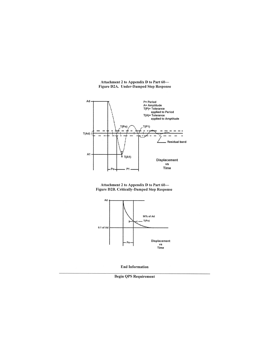
418
14 CFR Ch. I (1–1–24 Edition)
Pt. 60, App. D
c. Alternative method for control dynam-
ics evaluation.
(1) An alternative means for validating
control dynamics for aircraft with hydrau-
lically powered flight controls and artificial
feel systems is by the measurement of con-
trol force and rate of movement. For each
axis of pitch, roll, and yaw, the control must
be forced to its maximum extreme position
for the following distinct rates. These tests
are conducted under normal flight and
ground conditions.
VerDate Sep<11>2014
14:00 Mar 14, 2024
Jkt 262047
PO 00000
Frm 00428
Fmt 8010
Sfmt 8002
Q:\14\14V2.TXT
PC31
ER09MY08.053</GPH>
aworley on LAPBH6H6L3 with DISTILLER

419
Federal Aviation Administration, DOT
Pt. 60, App. D
(a) Static test—Slowly move the control so
that a full sweep is achieved within 95–105
seconds. A full sweep is defined as movement
of the controller from neutral to the stop,
usually aft or right stop, then to the oppo-
site stop, then to the neutral position.
(b) Slow dynamic test—Achieve a full
sweep within 8–12 seconds.
(c) Fast dynamic test—Achieve a full
sweep within 3–5 seconds.
N
OTE
: Dynamic sweeps may be limited to
forces not exceeding 100 lbs. (44.5 daN).
(d) Tolerances.
(i) Static test; see Table D2A, Flight Train-
ing Device (FTD) Objective Tests, Entries
2.a.1., 2.a.2., and 2.a.3.
(ii) Dynamic test—
±
2 lbs (0.9 daN) or
±
10%
on dynamic increment above static test.
E
ND
QPS R
EQUIREMENT
llllllllllllllllllllllll
B
EGIN
I
NFORMATION
d. The FAA is open to alternative means
that are justified and appropriate to the ap-
plication. For example, the method described
here may not apply to all manufacturers’
systems and certainly not to aircraft with
reversible control systems. Each case is con-
sidered on its own merit on an ad hoc basis.
If the FAA finds that alternative methods do
not result in satisfactory performance, more
conventionally accepted methods will have
to be used.
4. F
OR
A
DDITIONAL
I
NFORMATION ON THE
F
OL
-
LOWING
T
OPICS
, P
LEASE
R
EFER TO
A
PPENDIX
C
OF
T
HIS
P
ART
, A
TTACHMENT
2,
AND THE
I
NDICATED
P
ARAGRAPH
W
ITHIN
T
HAT
A
T
-
TACHMENT
•
Additional Information About Flight
Simulator Qualification for New or Deriva-
tive Helicopters, paragraph 8.
•
Engineering Simulator Validation Data,
paragraph 9.
•
Validation Test Tolerances, paragraph
11.
•
Validation Data Road Map, paragraph 12.
•
Acceptance Guidelines for Alternative
Avionics, paragraph 13.
•
Transport Delay Testing, paragraph 15.
•
Continuing Qualification Evaluation Val-
idation Data Presentation, paragraph 16.
E
ND
I
NFORMATION
llllllllllllllllllllllll
A
TTACHMENT
3
TO
A
PPENDIX
D
TO
P
ART
60—
FLIGHT TRAINING DEVICE (FTD) SUB-
JECTIVE EVALUATION
llllllllllllllllllllllll
B
EGIN
QPS R
EQUIREMENTS
1. R
EQUIREMENTS
a. Except for special use airport models, all
airport models required by this part must be
representations of real-world, operational
airports or representations of fictional air-
ports and must meet the requirements set
out in Tables D3B or D3C of this attachment,
as appropriate.
b. If fictional airports are used, the sponsor
must ensure that navigational aids and all
appropriate maps, charts, and other naviga-
tional reference material for the fictional
airports (and surrounding areas as nec-
essary) are compatible, complete, and accu-
rate with respect to the visual presentation
and the airport model of this fictional air-
port. An SOC must be submitted that ad-
dresses navigation aid installation and per-
formance and other criteria (including ob-
struction clearance protection) for all in-
strument approaches to the fictional air-
ports that are available in the simulator.
The SOC must reference and account for in-
formation in the terminal instrument proce-
dures manual and the construction and
availability of the required maps, charts, and
other navigational material. This material
must be clearly marked ‘‘for training pur-
poses only.’’
c. When the simulator is being used by an
instructor or evaluator for purposes of train-
ing, checking, or testing under this chapter,
only airport models classified as Class I,
Class II, or Class III may be used by the in-
structor or evaluator. Detailed descriptions/
definitions of these classifications are found
in Appendix F of this part.
d. When a person sponsors an FTD main-
tained by a person other than a U.S. certifi-
cate holder, the sponsor is accountable for
that FTD originally meeting, and continuing
to meet, the criteria under which it was
originally qualified and the appropriate Part
60 criteria, including the visual scenes and
airport models that may be used by instruc-
tors or evaluators for purposes of training,
checking, or testing under this chapter.
e. Neither Class II nor Class III airport vis-
ual models are required to appear on the
SOQ, and the method used for keeping in-
structors and evaluators apprised of the air-
port models that meet Class II or Class III
requirements on any given simulator is at
the option of the sponsor, but the method
used must be available for review by the
TPAA.
f. When an airport model represents a real
world airport and a permanent change is
made to that real world airport (e.g., a new
runway, an extended taxiway, a new lighting
system, a runway closure) without a written
extension grant from the responsible Flight
Standards office (described in paragraph 1.g.,
of this section), an update to that airport
VerDate Sep<11>2014
14:00 Mar 14, 2024
Jkt 262047
PO 00000
Frm 00429
Fmt 8010
Sfmt 8002
Q:\14\14V2.TXT
PC31
aworley on LAPBH6H6L3 with DISTILLER

420
14 CFR Ch. I (1–1–24 Edition)
Pt. 60, App. D
model must be made in accordance with the
following time limits:
(1) For a new airport runway, a runway ex-
tension, a new airport taxiway, a taxiway ex-
tension, or a runway/taxiway closure—with-
in 90 days of the opening for use of the new
airport runway, runway extension, new air-
port taxiway, or taxiway extension; or with-
in 90 days of the closure of the runway or
taxiway.
(2) For a new or modified approach light
system—within 45 days of the activation of
the new or modified approach light system.
(3) For other facility or structural changes
on the airport (e.g., new terminal, relocation
of Air Traffic Control Tower)—within 180
days of the opening of the new or changed fa-
cility or structure.
g. If a sponsor desires an extension to the
time limit for an update to a visual scene or
airport model or has an objection to what
must be updated in the specific airport
model requirement, the sponsor must pro-
vide a written extension request to the re-
sponsible Flight Standards office stating the
reason for the update delay and a proposed
completion date or provide an explanation
for the objection, explaining why the identi-
fied airport change will not have an impact
on flight training, testing, or checking. A
copy of this request or objection must also
be sent to the POI/TCPM.
h. Examples of situations that may war-
rant Class
_
III model designation by the
TPAA include the following:
(a) Training, testing, or checking on very
low visibility operations, including SMGCS
operations.
(b) Instrument operations training (includ-
ing instrument takeoff, departure, arrival,
approach, and missed approach training,
testing, or checking) using—
(i) A specific model that has been geo-
graphically ‘‘moved’’ to a different location
and aligned with an instrument procedure
for another airport.
(ii) A model that does not match changes
made at the real-world airport (or landing
area for helicopters) being modeled.
(iii) A model generated with an ‘‘off-board’’
or an ‘‘on-board’’ model development tool
(by providing proper latitude/longitude ref-
erence; correct runway or landing area ori-
entation, length, width, marking, and light-
ing information; and appropriate adjacent
taxiway location) to generate a facsimile of
a real world airport or landing area.
These airport models may be accepted by
the TPAA without individual observation
provided the sponsor provides the TPAA
with an acceptable description of the process
for determining the acceptability of a spe-
cific airport model, outlines the conditions
under which such an airport model may be
used, and adequately describes what restric-
tions will be applied to each resulting air-
port or landing area model.
E
ND
QPS R
EQUIREMENTS
llllllllllllllllllllllll
B
EGIN
I
NFORMATION
2. D
ISCUSSION
a. The subjective tests and the examina-
tion of functions provide a basis for evalu-
ating the capability of the FTD to perform
over a typical utilization period; deter-
mining that the FTD satisfactorily meets
the appropriate training/testing/checking ob-
jectives and competently simulates each re-
quired maneuver, procedure, or task; and
verifying correct operation of the FTD con-
trols, instruments, and systems. The items
in the list of operations tasks are for FTD
evaluation purposes only. They must not be
used to limit or exceed the authorizations
for use of a given level of FTD as found in
the Practical Test Standards or as approved
by the TPAA. All items in the following
paragraphs are subject to an examination of
function.
b. The List of Operations Tasks in Table
D3A addressing pilot functions and maneu-
vers is divided by flight phases. All simu-
lated helicopter systems functions will be as-
sessed for normal and, where appropriate, al-
ternate operations. Normal, abnormal, and
emergency operations associated with a
flight phase will be assessed during the eval-
uation of maneuvers or events within that
flight phase.
c. Systems to be evaluated are listed sepa-
rately under ‘‘Any Flight Phase’’ to ensure
appropriate attention to systems checks.
Operational navigation systems (including
inertial navigation systems, global posi-
tioning systems, or other long-range sys-
tems) and the associated electronic display
systems will be evaluated if installed. The
pilot will include in his report to the TPAA,
the effect of the system operation and any
system limitation.
d. At the request of the TPAA, the Pilot
may assess the FTD for a special aspect of a
sponsor’s training program during the func-
tions and subjective portion of an evalua-
tion. Such an assessment may include a por-
tion of a specific operation (e.g., a Line Ori-
ented Flight Training (LOFT) scenario) or
special emphasis items in the sponsor’s
training program. Unless directly related to
a requirement for the qualification level, the
results of such an evaluation would not nec-
essarily affect the qualification of the FTD.
e. The FAA intends to allow the use of
Class III airport models on a limited basis
when the sponsor provides the TPAA (or
other regulatory authority) an appropriate
analysis of the skills, knowledge, and abili-
ties (SKAs) necessary for competent per-
formance of the tasks in which this par-
ticular media element is used. The analysis
should describe the ability of the FTD/visual
VerDate Sep<11>2014
14:00 Mar 14, 2024
Jkt 262047
PO 00000
Frm 00430
Fmt 8010
Sfmt 8002
Q:\14\14V2.TXT
PC31
aworley on LAPBH6H6L3 with DISTILLER

421
Federal Aviation Administration, DOT
Pt. 60, App. D
media to provide an adequate environment
in which the required SKAs are satisfac-
torily performed and learned. The analysis
should also include the specific media ele-
ment, such as the visual scene or airport
model. Additional sources of information on
the conduct of task and capability analysis
may be found on the FAA’s Advanced Quali-
fication Program (AQP) Web site at:
http://
www.faa.gov/education
_
research/training/aqp.
E
ND
I
NFORMATION
llllllllllllllllllllllll
T
ABLE
D3A—T
ABLE OF
F
UNCTIONS AND
S
UBJECTIVE
T
ESTS
L
EVEL
7 FTD
QPS requirements
Entry No.
Operations tasks
Tasks in this table are subject to evaluation if appropriate for the helicopter simulated as indicated in the SOQ Configuration
List or a Level 7 FTD. Items not installed, not functional on the FTD, and not appearing on the SOQ Configuration List, are
not required to be listed as exceptions on the SOQ.
1. Preflight Procedures
1.a. ........................
Preflight Inspection (Flight Deck Only) switches, indicators, systems, and equipment.
1.b. ........................
APU/Engine start and run-up.
1.b.1. .....................
Normal start procedures.
1.b.2. .....................
Alternate start procedures.
1.b.3. .....................
Abnormal starts and shutdowns (hot start, hung start).
1.b.4. .....................
Rotor engagement.
1.b.5. .....................
System checks.
1.c. ........................
Taxiing—Ground.
1.c.1. .....................
Power required to taxi.
1.c.2. .....................
Brake effectiveness.
1.c.3. .....................
Ground handling.
1.c.4. .....................
Abnormal/emergency procedures, for example:
1.c.4.a. ..................
Brake system failure.
1.c.4.b. ..................
Ground resonance.
1.c.4.c. ..................
Other (listed on the SOQ).
1.d. ........................
Taxiing—Hover.
1.d.1. .....................
Takeoff to a hover.
1.d.2. .....................
Instrument response.
1.d.2.a. ..................
Engine instruments.
1.d.2.a. ..................
Flight instruments.
1.d.3. .....................
Hovering turns.
1.d.4. .....................
Hover power checks.
1.d.4.a. ..................
In ground effect (IGE).
1.d.4.b. ..................
Out of ground effect (OGE).
1.d.5. .....................
Crosswind/tailwind hover.
1.d.6. .....................
Abnormal/emergency procedures:
1.d.6.a. ..................
Engine failure.
1.d.6.b. ..................
Fuel governing system failure.
VerDate Sep<11>2014
14:00 Mar 14, 2024
Jkt 262047
PO 00000
Frm 00431
Fmt 8010
Sfmt 8002
Q:\14\14V2.TXT
PC31
aworley on LAPBH6H6L3 with DISTILLER

422
14 CFR Ch. I (1–1–24 Edition)
Pt. 60, App. D
T
ABLE
D3A—T
ABLE OF
F
UNCTIONS AND
S
UBJECTIVE
T
ESTS
L
EVEL
7 FTD—Continued
QPS requirements
Entry No.
Operations tasks
1.d.6.c. ..................
Settling with power (OGE).
1.d.6.d. ..................
Stability augmentation system failure.
1.d.6.e. ..................
Directional control malfunction (including Loss of Tail Rotor Effectiveness, LTE).
1.d.6.f. ...................
Other (listed on the SOQ).
1.e. ........................
Pre-takeoff Checks.
2. Takeoff and Departure Phase
2.a. ........................
Normal and Crosswind Takeoff.
2.a.1. .....................
From ground.
2.a.2. .....................
From hover.
2.a.3. .....................
Running.
2.a.4. .....................
Crosswind/tailwind.
2.a.5. .....................
Maximum performance.
2.b. ........................
Instrument.
2.c. ........................
Powerplant Failure During Takeoff.
2.c.1. .....................
Takeoff with engine failure after critical decision point (CDP).
2.d. ........................
Rejected Takeoff.
2.e. ........................
Instrument Departure.
2.f. .........................
Other (listed on the SOQ).
3. Climb
3.a. ........................
Normal.
3.b. ........................
Obstacle clearance.
3.c. ........................
Vertical.
3.d. ........................
One engine inoperative.
3.e. ........................
Other (listed on the SOQ).
4. Inflight Maneuvers
4.a. ........................
Performance.
4.b. ........................
Flying qualities.
4.c. ........................
Turns.
4.c.1. .....................
Timed.
4.c.2. .....................
Normal.
4.c.3. .....................
Steep.
4.d. ........................
Accelerations and decelerations.
4.e. ........................
High-speed vibrations.
4.f. .........................
Abnormal/emergency procedures, for example:
4.f.1. ......................
Engine fire.
4.f.2. ......................
Engine failure.
VerDate Sep<11>2014
14:00 Mar 14, 2024
Jkt 262047
PO 00000
Frm 00432
Fmt 8010
Sfmt 8002
Q:\14\14V2.TXT
PC31
aworley on LAPBH6H6L3 with DISTILLER

423
Federal Aviation Administration, DOT
Pt. 60, App. D
T
ABLE
D3A—T
ABLE OF
F
UNCTIONS AND
S
UBJECTIVE
T
ESTS
L
EVEL
7 FTD—Continued
QPS requirements
Entry No.
Operations tasks
4.f.2.a. ...................
Powerplant Failure—Multiengine Helicopters.
4.f.2.b. ...................
Powerplant Failure—Single-Engine Helicopters.
4.f.3. ......................
Inflight engine shutdown (and restart, if applicable).
4.f.4. ......................
Fuel governing system failures (e.g., FADEC malfunction).
4.f.5. ......................
Directional control malfunction.
4.f.6. ......................
Hydraulic failure.
4.f.7. ......................
Stability augmentation system failure.
4.f.8. ......................
Rotor vibrations.
4.f.9. ......................
Recovery From Unusual Attitudes.
4.f.10. ....................
Settling with Power.
4.g. ........................
Other (listed on the SOQ).
5. Instrument Procedures
5.a. ........................
Instrument Arrival.
5.b. ........................
Holding.
5.c. ........................
Precision Instrument Approach.
5.c.1. .....................
Normal—All engines operating.
5.c.2. .....................
Manually controlled—One or more engines inoperative.
5.c.3. .....................
Approach procedures:
5.c.3.a. ..................
PAR.
5.c.3.b. ..................
GPS.
5.c.3.c. ..................
ILS.
5.c.3.c.1. ...............
Manual (raw data).
5.c.3.c.2. ...............
Autopilot * only.
5.c.3.c.3. ...............
Flight director only.
5.c.3.c.4. ...............
Autopilot * and flight director (if appropriate) coupled.
5.c.3.d. ..................
Other (listed on the SOQ).
5.d. ........................
Non-precision Instrument Approach.
5.d.1. .....................
Normal—All engines operating.
5.d.2. .....................
One or more engines inoperative.
5.d.3. .....................
Approach procedures:
5.d.3.a. ..................
NDB.
5.d.3.b. ..................
VOR, RNAV, TACAN, GPS.
5.d.3.c. ..................
ASR.
5.d.3.d. ..................
Circling.
5.d.3.e. ..................
Helicopter only.
5.d.3.f. ...................
Other (listed on the SOQ).
VerDate Sep<11>2014
14:00 Mar 14, 2024
Jkt 262047
PO 00000
Frm 00433
Fmt 8010
Sfmt 8002
Q:\14\14V2.TXT
PC31
aworley on LAPBH6H6L3 with DISTILLER

424
14 CFR Ch. I (1–1–24 Edition)
Pt. 60, App. D
T
ABLE
D3A—T
ABLE OF
F
UNCTIONS AND
S
UBJECTIVE
T
ESTS
L
EVEL
7 FTD—Continued
QPS requirements
Entry No.
Operations tasks
5.e. ........................
Missed Approach.
5.e.1. .....................
All engines operating.
5.e.2. .....................
One or more engines inoperative.
5.e.3. .....................
Stability augmentation system failure.
5.e.4. .....................
Other (listed on the SOQ).
6. Landings and Approaches to Landings
6.a. ........................
Visual Approaches.
6.a.1. .....................
Normal.
6.a.2. .....................
Steep.
6.a.3. .....................
Shallow.
6.a.4. .....................
Crosswind.
6.b. ........................
Landings.
6.b.1. .....................
Normal.
6.b.1.a. ..................
Running.
6.b.1.b. ..................
From Hover.
6.b.2. .....................
Crosswind.
6.b.3. .....................
Tailwind.
6.b.4. .....................
One or more engines inoperative.
6.b.5. .....................
Rejected Landing.
6.b.6. .....................
Other (listed on the SOQ).
7. Normal and Abnormal Procedures (any phase of flight)
7.a. ........................
Helicopter and powerplant systems operation (as applicable).
7.a.1. .....................
Anti-icing/deicing systems.
7.a.2. .....................
Auxiliary powerplant.
7.a.3. .....................
Communications.
7.a.4. .....................
Electrical system.
7.a.5. .....................
Environmental system.
7.a.6. .....................
Fire detection and suppression.
7.a.7. .....................
Flight control system.
7.a.8. .....................
Fuel system.
7.a.9. .....................
Engine oil system.
7.a.10. ...................
Hydraulic system.
7.a.11. ...................
Landing gear.
7.a.12. ...................
Oxygen.
7.a.13. ...................
Pneumatic.
7.a.14. ...................
Powerplant.
VerDate Sep<11>2014
14:00 Mar 14, 2024
Jkt 262047
PO 00000
Frm 00434
Fmt 8010
Sfmt 8002
Q:\14\14V2.TXT
PC31
aworley on LAPBH6H6L3 with DISTILLER

425
Federal Aviation Administration, DOT
Pt. 60, App. D
T
ABLE
D3A—T
ABLE OF
F
UNCTIONS AND
S
UBJECTIVE
T
ESTS
L
EVEL
7 FTD—Continued
QPS requirements
Entry No.
Operations tasks
7.a.15. ...................
Flight control computers.
7.a.16. ...................
Fly-by-wire controls.
7.a.17. ...................
Stabilizer.
7.a.18. ...................
Stability augmentation and control augmentation system(s).
7.a.19. ...................
Other (listed on the SOQ).
7.b. ........................
Flight management and guidance system (as applicable).
7.b.1. .....................
Airborne radar.
7.b.2. .....................
Automatic landing aids.
7.b.3. .....................
Autopilot.*
7.b.4. .....................
Collision avoidance system.
7.b.5. .....................
Flight data displays.
7.b.6. .....................
Flight management computers.
7.b.7. .....................
Head-up displays.
7.b.8. .....................
Navigation systems.
7.b.9. .....................
Other (listed on the SOQ).
8. Emergency Procedures (as applicable)
8.a. ........................
Autorotative Landing.
8.b. ........................
Air hazard avoidance.
8.c. ........................
Ditching.
8.d. ........................
Emergency evacuation.
8.e. ........................
Inflight fire and smoke removal.
8.f. .........................
Retreating blade stall recovery.
8.g. ........................
Mast bumping.
8.h. ........................
Loss of tail rotor effectiveness.
8.i. .........................
Other (listed on the SOQ).
9. Postflight Procedures
9.a. ........................
After-Landing Procedures.
9.b. ........................
Parking and Securing.
9.b.1. .....................
Engine and systems operation.
9.b.2. .....................
Parking brake operation.
9.b.3. .....................
Rotor brake operation.
9.b.4. .....................
Abnormal/emergency procedures.
10. Instructor Operating Station (IOS), as appropriate
10.a. ......................
Power Switch(es).
10.b. ......................
Helicopter conditions.
10.b.1. ...................
Gross weight, center of gravity, fuel loading and allocation, etc.
VerDate Sep<11>2014
14:00 Mar 14, 2024
Jkt 262047
PO 00000
Frm 00435
Fmt 8010
Sfmt 8002
Q:\14\14V2.TXT
PC31
aworley on LAPBH6H6L3 with DISTILLER

426
14 CFR Ch. I (1–1–24 Edition)
Pt. 60, App. D
T
ABLE
D3A—T
ABLE OF
F
UNCTIONS AND
S
UBJECTIVE
T
ESTS
L
EVEL
7 FTD—Continued
QPS requirements
Entry No.
Operations tasks
10.b.2. ...................
Helicopter systems status.
10.b.3. ...................
Ground crew functions (e.g., ext. power).
10.c. ......................
Airports.
10.c.1. ...................
Selection.
10.c.2. ...................
Runway selection.
10.c.3. ...................
Preset positions (e.g., ramp, over final approach fix).
10.d. ......................
Environmental controls.
10.d.1. ...................
Temperature.
10.d.2. ...................
Climate conditions (e.g., ice, rain).
10.d.3. ...................
Wind speed and direction.
10.e. ......................
Helicopter system malfunctions.
10.e.1. ...................
Insertion/deletion.
10.e.2. ...................
Problem clear.
10.f. .......................
Locks, Freezes, and Repositioning.
10.f.1. ....................
Problem (all) freeze/release.
10.f.2. ....................
Position (geographic) freeze/release.
10.f.3. ....................
Repositioning (locations, freezes, and releases).
10.f.4. ....................
Ground speed control.
10.g. ......................
Sound Controls.
10.g.1. ...................
On/off/adjustment.
10.h. ......................
Control Loading System (as applicable).
10.h.1. ...................
On/off/emergency stop.
10.i. .......................
Observer Stations.
10.i.1. ....................
Position.
10.i.2. ....................
Adjustments.
* ‘‘Autopilot’’ means attitude retention mode of operation.
T
ABLE
D3B—T
ABLE OF
F
UNCTIONS AND
S
UBJECTIVE
T
ESTS
A
IRPORT OR
L
ANDING
A
REA
C
ONTENT
R
EQUIREMENTS FOR
Q
UALIFICATION AT
L
EVEL
7 FTD
QPS requirements
Entry No.
Operations tasks
This table specifies the minimum airport visual model content and functionality to qualify an FTD at the indicated level. This
table applies only to the airport/helicopter landing area scenes required for FTD qualification.
1. ..............
Functional test content requirements for Level 7 FTDs. The following is the minimum airport/landing area model
content requirement to satisfy visual capability tests, and provides suitable visual cues to allow completion of all
functions and subjective tests described in this attachment for Level 7 FTDs.
VerDate Sep<11>2014
14:00 Mar 14, 2024
Jkt 262047
PO 00000
Frm 00436
Fmt 8010
Sfmt 8002
Q:\14\14V2.TXT
PC31
aworley on LAPBH6H6L3 with DISTILLER

427
Federal Aviation Administration, DOT
Pt. 60, App. D
T
ABLE
D3B—T
ABLE OF
F
UNCTIONS AND
S
UBJECTIVE
T
ESTS
A
IRPORT OR
L
ANDING
A
REA
C
ONTENT
R
EQUIREMENTS FOR
Q
UALIFICATION AT
L
EVEL
7 FTD—Continued
QPS requirements
Entry No.
Operations tasks
1.a. ...........
A minimum of one (1) representative airport and one (1) representative helicopter landing area model. The airport
and the helicopter landing area may be contained within the same visual model. If this option is selected, the ap-
proach path to the airport runway(s) and the approach path to the helicopter landing area must be different. The
model(s) used to meet the following requirements may be demonstrated at either a fictional or a real-world air-
port or helicopter landing area, but each must be acceptable to the sponsor’s TPAA, selectable from the IOS,
and listed on the SOQ.
1.b. ...........
Fidelity of the Visual Scene. The fidelity of the visual scene must be sufficient for the aircrew to visually identify the
airport and/or helicopter landing area; determine the position of the simulated helicopter within the visual scene;
successfully accomplish take-offs, approaches, and landings; and maneuver around the airport and/or helicopter
landing area on the ground, or hover taxi, as necessary.
1.b.1. ........
For each of the airport/helicopter landing areas described in 1.a., the FTD visual system must be able to provide at
least the following:
1.b.1.a. .....
A night and twilight (dusk) environment.
1.b.1.b. .....
A daylight environment.
1.c. ...........
Runways:
1.c.1. ........
Visible runway number.
1.c.2. ........
Runway threshold elevations and locations must be modeled to provide sufficient correlation with helicopter sys-
tems (e.g., altimeter).
1.c.3. ........
Runway surface and markings.
1.c.4. ........
Lighting for the runway in use including runway edge and centerline.
1.c.5. ........
Lighting, visual approach aid (VASI or PAPI) and approach lighting of appropriate colors.
1.c.6 .........
Taxiway lights.
1.d. ...........
Helicopter landing area.
1.d.1. ........
Standard heliport designation (‘‘H’’) marking, properly sized and oriented.
1.d.2. ........
Perimeter markings for the Touchdown and Lift-Off Area (TLOF) or the Final Approach and Takeoff Area (FATO),
as appropriate.
1.d.3. ........
Perimeter lighting for the TLOF or the FATO areas, as appropriate.
1.d.4. ........
Appropriate markings and lighting to allow movement from the runway or helicopter landing area to another part of
the landing facility.
2. ..............
Visual scene management.
The following is the minimum visual scene management requirements for a Level 7 FTD.
2.a. ...........
Runway and helicopter landing area approach lighting must fade into view appropriately in accordance with the en-
vironmental conditions set in the FTD.
2.b. ...........
The direction of strobe lights, approach lights, runway edge lights, visual landing aids, runway centerline lights,
threshold lights, touchdown zone lights, and TLOF or FATO lights must be replicated.
3. ..............
Visual feature recognition.
The following are the minimum distances at which runway features must be visible. Distances are measured from
runway threshold or a helicopter landing area to a helicopter aligned with the runway or helicopter landing area
on an extended 3
°
glide-slope in simulated meteorological conditions. For circling approaches, all tests apply to
the runway used for the initial approach and to the runway of intended landing.
3.a. ...........
For runways: Runway definition, strobe lights, approach lights, and edge lights from 5 sm (8 km) of the threshold.
3.b. ...........
For runways: Centerline lights and taxiway definition from 3 sm (5 km).
3.c. ...........
For runways: Visual Approach Aid lights (VASI or PAPI) from 5 sm (8 km) of the threshold.
3.d. ...........
For runways: Runway threshold lights and touchdown zone from 2 sm (3 km).
VerDate Sep<11>2014
14:00 Mar 14, 2024
Jkt 262047
PO 00000
Frm 00437
Fmt 8010
Sfmt 8002
Q:\14\14V2.TXT
PC31
aworley on LAPBH6H6L3 with DISTILLER

428
14 CFR Ch. I (1–1–24 Edition)
Pt. 60, App. D
T
ABLE
D3B—T
ABLE OF
F
UNCTIONS AND
S
UBJECTIVE
T
ESTS
A
IRPORT OR
L
ANDING
A
REA
C
ONTENT
R
EQUIREMENTS FOR
Q
UALIFICATION AT
L
EVEL
7 FTD—Continued
QPS requirements
Entry No.
Operations tasks
3.e. ...........
For runways and helicopter landing areas: Markings within range of landing lights for night/twilight scenes and the
surface resolution test on daylight scenes, as required.
3.f. ............
For circling approaches: The runway of intended landing and associated lighting must fade into view in a non-dis-
tracting manner.
3.g. ...........
For helicopter landing areas: Landing direction lights and raised FATO lights from 1 sm (1.5 km).
3.h. ...........
For helicopter landing areas: Flush mounted FATO lights, TLOF lights, and the lighted windsock from 0.5 sm (750
m).
4. ..............
Airport or Helicopter Landing Area Model Content.
The following prescribes the minimum requirements for an airport/helicopter landing area visual model and identi-
fies other aspects of the environment that must correspond with that model for a Level 7 FTD. For circling ap-
proaches, all tests apply to the runway used for the initial approach and to the runway of intended landing. If all
runways or landing areas in a visual model used to meet the requirements of this attachment are not designated
as ‘‘in use,’’ then the ‘‘in use’’ runways/landing areas must be listed on the SOQ (e.g., KORD, Rwys 9R, 14L,
22R). Models of airports or helicopter landing areas with more than one runway or landing area must have all
significant runways or landing areas not ‘‘in-use’’ visually depicted for airport/runway/landing area recognition
purposes. The use of white or off white light strings that identify the runway or landing area for twilight and night
scenes are acceptable for this requirement; and rectangular surface depictions are acceptable for daylight
scenes. A visual system’s capabilities must be balanced between providing visual models with an accurate rep-
resentation of the airport and a realistic representation of the surrounding environment. Each runway or heli-
copter landing area designated as an ‘‘in-use’’ runway or area must include the following detail that is developed
using airport pictures, construction drawings and maps, or other similar data, or developed in accordance with
published regulatory material; however, this does not require that such models contain details that are beyond
the design capability of the currently qualified visual system. Only one ‘‘primary’’ taxi route from parking to the
runway end or helicopter takeoff/landing area will be required for each ‘‘in-use’’ runway or helicopter takeoff/land-
ing area.
4.a. ...........
The surface and markings for each ‘‘in-use’’ runway or helicopter landing area must include the following:
4.a.1. ........
For airports: Runway threshold markings, runway numbers, touchdown zone markings, fixed distance markings,
runway edge markings, and runway centerline stripes.
4.a.2. ........
For helicopter landing areas: Markings for standard heliport identification (‘‘H’’) and TLOF, FATO, and safety areas.
4.b. ...........
The lighting for each ‘‘in-use’’ runway or helicopter landing area must include the following:
4.b.1. ........
For airports: Runway approach, threshold, edge, end, centerline (if applicable), touchdown zone (if applicable),
leadoff, and visual landing aid lights or light systems for that runway.
4.b.2. ........
For helicopter landing areas: Landing direction, raised and flush FATO, TLOF, windsock lighting.
4.c. ...........
The taxiway surface and markings associated with each ‘‘in-use’’ runway or helicopter landing area must include
the following:
4.c.1. ........
For airports: Taxiway edge, centerline (if appropriate), runway hold lines, and ILS critical area(s).
4.c.2. ........
For helicopter landing areas: Taxiways, taxi routes, and aprons.
4.d. ...........
The taxiway lighting associated with each ‘‘in-use’’ runway or helicopter landing area must include the following:
4.d.1. ........
For airports: Taxiway edge, centerline (if appropriate), runway hold lines, ILS critical areas.
4.d.2. ........
For helicopter landing areas: Taxiways, taxi routes, and aprons.
4.d.3. ........
For airports: Taxiway lighting of correct color.
4.e. ...........
Airport signage associated with each ‘‘in-use’’ runway or helicopter landing area must include the following:
4.e.1. ........
For airports: Signs for runway distance remaining, intersecting runway with taxiway, and intersecting taxiway with
taxiway.
4.e.2. ........
For helicopter landing areas: As appropriate for the model used.
4.f. ............
Required visual model correlation with other aspects of the airport or helicopter landing environment simulation:
VerDate Sep<11>2014
14:00 Mar 14, 2024
Jkt 262047
PO 00000
Frm 00438
Fmt 8010
Sfmt 8002
Q:\14\14V2.TXT
PC31
aworley on LAPBH6H6L3 with DISTILLER

429
Federal Aviation Administration, DOT
Pt. 60, App. D
T
ABLE
D3B—T
ABLE OF
F
UNCTIONS AND
S
UBJECTIVE
T
ESTS
A
IRPORT OR
L
ANDING
A
REA
C
ONTENT
R
EQUIREMENTS FOR
Q
UALIFICATION AT
L
EVEL
7 FTD—Continued
QPS requirements
Entry No.
Operations tasks
4.f.1. .........
The airport or helicopter landing area model must be properly aligned with the navigational aids that are associated
with operations at the ‘‘in-use’’ runway or helicopter landing area.
4.f.2. .........
The simulation of runway or helicopter landing area contaminants must be correlated with the displayed runway
surface and lighting, if applicable.
5. ..............
Correlation with helicopter and associated equipment.
The following are the minimum correlation comparisons that must be made for a Level 7 FTD.
5.a. ...........
Visual system compatibility with aerodynamic programming.
5.b. ...........
Visual cues to assess sink rate and depth perception during landings.
5.c. ...........
Accurate portrayal of environment relating to FTD attitudes.
5.d. ...........
The visual scene must correlate with integrated helicopter systems, where installed (e.g., terrain, traffic and weath-
er avoidance systems and Head-up Guidance System (HGS)).
5.e. ...........
Representative visual effects for each visible, own-ship, helicopter external light(s)—taxi and landing light lobes (in-
cluding independent operation, if appropriate).
5.f. ............
The effect of rain removal devices.
6. ..............
Scene quality.
The following are the minimum scene quality tests that must be conducted for a Level 7 FTD.
6.a. ...........
System light points must be free from distracting jitter, smearing and streaking.
6.b. ...........
Demonstration of occulting through each channel of the system in an operational scene.
6.c. ...........
Six discrete light step controls (0–5).
7. ..............
Special weather representations, which include visibility and RVR, measured in terms of distance.
Visibility/RVR checked at 2,000 ft (600 m) above the airport or helicopter landing area and at two heights below
2,000 ft with at least 500 ft of separation between the measurements. The measurements must be taken within a
radius of 10 sm (16 km) from the airport or helicopter landing area.
7.a. ...........
Effects of fog on airport lighting such as halos and defocus.
7.b. ...........
Effect of own-ship lighting in reduced visibility, such as reflected glare, including landing lights, strobes, and bea-
cons.
8. ..............
Instructor control of the following:
The following are the minimum instructor controls that must be available in a Level 7 FTD.
8.a. ...........
Environmental effects: E.g., cloud base, cloud effects, cloud density, visibility in statute miles/kilometers and RVR
in feet/meters.
8.b. ...........
Airport or helicopter landing area selection.
8.c. ...........
Airport or helicopter landing area lighting, including variable intensity.
8.d. ...........
Dynamic effects including ground and flight traffic.
End QPS Requirement
Begin Information
9. ..............
An example of being able to combine two airport models to achieve two ‘‘in-use’’ runways: One runway designated
as the ‘‘in-use’’ runway in the first model of the airport, and the second runway designated as the ‘‘in-use’’ run-
way in the second model of the same airport. For example, the clearance is for the ILS approach to Runway 27,
Circle to Land on Runway 18 right. Two airport visual models might be used: The first with Runway 27 des-
ignated as the ‘‘in use’’ runway for the approach to runway 27, and the second with Runway 18 Right designated
as the ‘‘in use’’ runway. When the pilot breaks off the ILS approach to runway 27, the instructor may change to
the second airport visual model in which runway 18 Right is designated as the ‘‘in use’’ runway, and the pilot
would make a visual approach and landing. This process is acceptable to the FAA as long as the temporary
interruption due to the visual model change is not distracting to the pilot.
VerDate Sep<11>2014
14:00 Mar 14, 2024
Jkt 262047
PO 00000
Frm 00439
Fmt 8010
Sfmt 8002
Q:\14\14V2.TXT
PC31
aworley on LAPBH6H6L3 with DISTILLER

430
14 CFR Ch. I (1–1–24 Edition)
Pt. 60, App. D
T
ABLE
D3B—T
ABLE OF
F
UNCTIONS AND
S
UBJECTIVE
T
ESTS
A
IRPORT OR
L
ANDING
A
REA
C
ONTENT
R
EQUIREMENTS FOR
Q
UALIFICATION AT
L
EVEL
7 FTD—Continued
QPS requirements
Entry No.
Operations tasks
10. ............
Sponsors are not required to provide every detail of a runway, but the detail that is provided should be correct
within reasonable limits.
End Information
T
ABLE
D3C—T
ABLE OF
F
UNCTIONS AND
S
UBJECTIVE
T
ESTS
L
EVEL
7 FTD V
ISUAL
R
EQUIREMENTS
A
DDITIONAL
V
ISUAL
M
ODELS
B
EYOND
M
INIMUM
R
EQUIRED FOR
Q
UALIFICATION
C
LASS
II A
IRPORT
OR
H
ELICOPTER
L
ANDING
A
REA
M
ODELS
QPS requirements
Entry No.
Operations tasks
This table specifies the minimum airport or helicopter landing area visual model content and functionality necessary to add vis-
ual models to an FTD’s visual model library (i.e., beyond those necessary for qualification at the stated level) without the ne-
cessity of further involvement of the responsible Flight Standards office or TPAA.
1. ..............
Visual scene management.
The following is the minimum visual scene management requirements.
1.a. ...........
The installation and direction of the following lights must be replicated for the ‘‘in-use’’ surface:
1.a.1. ........
For ‘‘in-use’’ runways: Strobe lights, approach lights, runway edge lights, visual landing aids, runway centerline
lights, threshold lights, and touchdown zone lights.
1.a.2. ........
For ‘‘in-use’’ helicopter landing areas: Ground level TLOF perimeter lights, elevated TLOF perimeter lights (if appli-
cable), Optional TLOF lights (if applicable), ground FATO perimeter lights, elevated TLOF lights (if applicable),
landing direction lights.
2. ..............
Visual feature recognition.
The following are the minimum distances at which runway or landing area features must be visible. Distances are
measured from runway threshold or a helicopter landing area to an aircraft aligned with the runway or helicopter
landing area on a 3
°
glide-slope from the aircraft to the touchdown point, in simulated meteorological conditions.
For circling approaches, all tests apply to the runway used for the initial approach and to the runway of intended
landing.
2.a. ...........
For Runways.
2.a.1. ........
Strobe lights, approach lights, and edge lights from 5 sm (8 km) of the threshold.
2.a.2. ........
Centerline lights and taxiway definition from 3 sm (5 km).
2.a.3. ........
Visual Approach Aid lights (VASI or PAPI) from 5 sm (8 km) of the threshold.
2.a.4. ........
Threshold lights and touchdown zone lights from 2 sm (3 km).
2.a.5. ........
Markings within range of landing lights for night/twilight (dusk) scenes and as required by the surface resolution
test on daylight scenes.
2.a.6. ........
For circling approaches, the runway of intended landing and associated lighting must fade into view in a non-dis-
tracting manner.
2.b. ...........
For Helicopter landing areas.
2.b.1. ........
Landing direction lights and raised FATO lights from 2 sm (3 km).
2.b.2. ........
Flush mounted FATO lights, TOFL lights, and the lighted windsock from 1 sm (1500 m).
2.b.3. ........
Hover taxiway lighting (yellow/blue/yellow cylinders) from TOFL area.
2.b.4. ........
Markings within range of landing lights for night/twilight (dusk) scenes and as required by the surface resolution
test on daylight scenes.
VerDate Sep<11>2014
14:00 Mar 14, 2024
Jkt 262047
PO 00000
Frm 00440
Fmt 8010
Sfmt 8002
Q:\14\14V2.TXT
PC31
aworley on LAPBH6H6L3 with DISTILLER

431
Federal Aviation Administration, DOT
Pt. 60, App. D
T
ABLE
D3C—T
ABLE OF
F
UNCTIONS AND
S
UBJECTIVE
T
ESTS
L
EVEL
7 FTD V
ISUAL
R
EQUIREMENTS
A
DDITIONAL
V
ISUAL
M
ODELS
B
EYOND
M
INIMUM
R
EQUIRED FOR
Q
UALIFICATION
C
LASS
II A
IRPORT
OR
H
ELICOPTER
L
ANDING
A
REA
M
ODELS
—Continued
QPS requirements
Entry No.
Operations tasks
3. ..............
Airport or Helicopter Landing Area Model Content.
The following prescribes the minimum requirements for what must be provided in an airport visual model and iden-
tifies other aspects of the airport environment that must correspond with that model. The detail must be devel-
oped using airport pictures, construction drawings and maps, or other similar data, or developed in accordance
with published regulatory material; however, this does not require that airport or helicopter landing area models
contain details that are beyond the designed capability of the currently qualified visual system. For circling ap-
proaches, all requirements of this section apply to the runway used for the initial approach and to the runway of
intended landing. Only one ‘‘primary’’ taxi route from parking to the runway end or helicopter takeoff/landing area
will be required for each ‘‘in-use’’ runway or helicopter takeoff/landing area.
3.a. ...........
The surface and markings for each ‘‘in-use’’ runway or helicopter landing area must include the following:
3.a.1. ........
For airports: Runway threshold markings, runway numbers, touchdown zone markings, fixed distance markings,
runway edge markings, and runway centerline stripes.
3.a.2. ........
For helicopter landing areas: Standard heliport marking (‘‘H’’), TOFL, FATO, and safety areas.
3.b. ...........
The lighting for each ‘‘in-use’’ runway or helicopter landing area must include the following:
3.b.1. ........
For airports: Runway approach, threshold, edge, end, centerline (if applicable), touchdown zone (if applicable),
leadoff, and visual landing aid lights or light systems for that runway.
3.b.2. ........
For helicopter landing areas: Landing direction, raised and flush FATO, TOFL, windsock lighting.
3.c. ...........
The taxiway surface and markings associated with each ‘‘in-use’’ runway or helicopter landing area must include
the following:
3.c.1. ........
For airports: Taxiway edge, centerline (if appropriate), runway hold lines, and ILS critical area(s).
3.c.2. ........
For helicopter landing areas: Taxiways, taxi routes, and aprons.
3.d. ...........
The taxiway lighting associated with each ‘‘in-use’’ runway or helicopter landing area must include the following:
3.d.1. ........
For airports: Runway edge, centerline (if appropriate), runway hold lines, ILS critical areas.
3.d.2. ........
For helicopter landing areas: Taxiways, taxi routes, and aprons.
4. ..............
Required visual model correlation with other aspects of the airport environment simulation.
The following are the minimum visual model correlation tests that must be conducted for Level 7 FTD.
4.a. ...........
The airport model must be properly aligned with the navigational aids that are associated with operations at the
‘‘in-use’’ runway.
4.b. ...........
Slopes in runways, taxiways, and ramp areas, if depicted in the visual scene, must not cause distracting or unreal-
istic effects.
5. ..............
Correlation with helicopter and associated equipment.
The following are the minimum correlation comparisons that must be made.
5.a. ...........
Visual system compatibility with aerodynamic programming.
5.b. ...........
Accurate portrayal of environment relating to flight simulator attitudes.
5.c. ...........
Visual cues to assess sink rate and depth perception during landings.
6. ..............
Scene quality.
The following are the minimum scene quality tests that must be conducted.
6.a. ...........
Light points free from distracting jitter, smearing or streaking.
6.b. ...........
Surfaces and textural cues free from apparent and distracting quantization (aliasing).
7. ..............
Instructor controls of the following.
The following are the minimum instructor controls that must be available.
7.a. ...........
Environmental effects, e.g., cloud base (if used), cloud effects, cloud density, visibility in statute miles/kilometers
and RVR in feet/meters.
VerDate Sep<11>2014
14:00 Mar 14, 2024
Jkt 262047
PO 00000
Frm 00441
Fmt 8010
Sfmt 8002
Q:\14\14V2.TXT
PC31
aworley on LAPBH6H6L3 with DISTILLER

432
14 CFR Ch. I (1–1–24 Edition)
Pt. 60, App. D
T
ABLE
D3C—T
ABLE OF
F
UNCTIONS AND
S
UBJECTIVE
T
ESTS
L
EVEL
7 FTD V
ISUAL
R
EQUIREMENTS
A
DDITIONAL
V
ISUAL
M
ODELS
B
EYOND
M
INIMUM
R
EQUIRED FOR
Q
UALIFICATION
C
LASS
II A
IRPORT
OR
H
ELICOPTER
L
ANDING
A
REA
M
ODELS
—Continued
QPS requirements
Entry No.
Operations tasks
7.b. ...........
Airport/Heliport selection.
7.c. ...........
Airport/Heliport lighting including variable intensity.
7.d. ...........
Dynamic effects including ground and flight traffic.
End QPS Requirements
Begin Information
8. ..............
Sponsors are not required to provide every detail of a runway or helicopter landing area, but the detail that is pro-
vided must be correct within the capabilities of the system.
End Information
T
ABLE
D3D—T
ABLE OF
F
UNCTIONS
A
ND
S
UBJECTIVE
T
ESTS
L
EVEL
6 FTD
QPS requirements
Entry No.
Operations tasks
Tasks in this table are subject to evaluation if appropriate for the helicopter simulated as indicated in the SOQ Configuration
List or for a Level 6 FTD. Items not installed or not functional on the FTD and not appearing on the SOQ Configuration List,
are not required to be listed as exceptions on the SOQ.
1. Preflight Procedures
1.a. ........................
Preflight Inspection (Flight Deck Only) switches, indicators, systems, and equipment.
1.b. ........................
APU/Engine start and run-up.
1.b.1. .....................
Normal start procedures.
1.b.2. .....................
Alternate start procedures.
1.b.3. .....................
Abnormal starts and shutdowns.
1.b.4. .....................
Rotor engagement.
1.b.5 ......................
System checks.
2. Takeoff and Departure Phase
2.a. ........................
Instrument.
2.b. ........................
Takeoff with engine failure after critical decision point (CDP).
3. Climb
3.a. ........................
Normal.
3.b. ........................
One engine inoperative.
4. Inflight Maneuvers
4.a. ........................
Performance.
4.b. ........................
Flying qualities.
4.c. ........................
Turns.
4.c.1. .....................
Timed.
4.c.2. .....................
Normal.
4.c.3. .....................
Steep.
4.d. ........................
Accelerations and decelerations.
VerDate Sep<11>2014
14:00 Mar 14, 2024
Jkt 262047
PO 00000
Frm 00442
Fmt 8010
Sfmt 8002
Q:\14\14V2.TXT
PC31
aworley on LAPBH6H6L3 with DISTILLER

433
Federal Aviation Administration, DOT
Pt. 60, App. D
T
ABLE
D3D—T
ABLE OF
F
UNCTIONS
A
ND
S
UBJECTIVE
T
ESTS
L
EVEL
6 FTD—Continued
QPS requirements
Entry No.
Operations tasks
4.e. ........................
Abnormal/emergency procedures:
4.e.1. .....................
Engine fire.
4.e.2. .....................
Engine failure.
4.e.3. .....................
In-flight engine shutdown (and restart, if applicable).
4.e.4. .....................
Fuel governing system failures (e.g., FADEC malfunction).
4.e.5. .....................
Directional control malfunction (restricted to the extent that the maneuver may not terminate in a landing).
4.e.6. .....................
Hydraulic failure.
4.e.7. .....................
Stability augmentation system failure.
5. Instrument Procedures
5.a. ........................
Holding.
5.b. ........................
Precision Instrument Approach.
5.b.1. .....................
All engines operating.
5.b.2. .....................
One or more engines inoperative.
5.b.3. .....................
Approach procedures:
5.b.4. .....................
PAR.
5.b.5. .....................
ILS.
5.b.6. .....................
Manual (raw data).
5.b.7. .....................
Flight director only.
5.b.8. .....................
Autopilot* and flight director (if appropriate) coupled.
5.c. ........................
Non-precision Instrument Approach.
5.c. ........................
Normal—All engines operating.
5.c. ........................
One or more engines inoperative.
5.c. ........................
Approach procedures:
5.c.1. .....................
NDB.
5.c.2. .....................
VOR, RNAV, TACAN, GPS.
5.c.3. .....................
ASR.
5.c.4. .....................
Helicopter only.
5.d. ........................
Missed Approach.
5.d.1. .....................
All engines operating.
5.d.2. .....................
One or more engines inoperative.
5.d.3. .....................
Stability augmentation system failure.
6. Normal and Abnormal Procedures (any phase of flight)
6.a. ........................
Helicopter and powerplant systems operation (as applicable).
6.a.1. .....................
Anti-icing/deicing systems.
6.a.2. .....................
Auxiliary power-plant.
6.a.3. .....................
Communications.
VerDate Sep<11>2014
14:00 Mar 14, 2024
Jkt 262047
PO 00000
Frm 00443
Fmt 8010
Sfmt 8002
Q:\14\14V2.TXT
PC31
aworley on LAPBH6H6L3 with DISTILLER

434
14 CFR Ch. I (1–1–24 Edition)
Pt. 60, App. D
T
ABLE
D3D—T
ABLE OF
F
UNCTIONS
A
ND
S
UBJECTIVE
T
ESTS
L
EVEL
6 FTD—Continued
QPS requirements
Entry No.
Operations tasks
6.a.4. .....................
Electrical system.
6.a.5. .....................
Environmental system.
6.a.6. .....................
Fire detection and suppression.
6.a.7. .....................
Flight control system.
6.a.8. .....................
Fuel system.
6.a.9. .....................
Engine oil system.
6.a.10. ...................
Hydraulic system.
6.a.11 ....................
Landing gear.
6.a.12. ...................
Oxygen.
6.a.13. ...................
Pneumatic.
6.a.14. ...................
Powerplant.
6.a.15. ...................
Flight control computers.
6.a.16. ...................
Stability augmentation and control augmentation system(s).
6.b. ........................
Flight management and guidance system (as applicable).
6.b.1. .....................
Airborne radar.
6.b.2. .....................
Automatic landing aids.
6.b.3. .....................
Autopilot.*
6.b.4. .....................
Collision avoidance system.
6.b.5. .....................
Flight data displays.
6.b.6. .....................
Flight management computers.
6.b.7. .....................
Navigation systems.
7. Postflight Procedures
7.a. ........................
Parking and Securing.
7.b. ........................
Engine and systems operation.
7.c. ........................
Parking brake operation.
7.d. ........................
Rotor brake operation.
7.e. ........................
Abnormal/emergency procedures.
8. Instructor Operating Station (IOS), as appropriate
8.a. ........................
Power Switch(es).
8.b.1. .....................
Helicopter conditions.
8.b.2. .....................
Gross weight, center of gravity, fuel loading and allocation, etc.
8.b.3. .....................
Helicopter systems status.
8.b.4. .....................
Ground crew functions (e.g., ext. power).
8.c. ........................
Airports and landing areas.
8.c.1. .....................
Number and selection.
8.c.2. .....................
Runway or landing area selection.
VerDate Sep<11>2014
14:00 Mar 14, 2024
Jkt 262047
PO 00000
Frm 00444
Fmt 8010
Sfmt 8002
Q:\14\14V2.TXT
PC31
aworley on LAPBH6H6L3 with DISTILLER

435
Federal Aviation Administration, DOT
Pt. 60, App. D
T
ABLE
D3D—T
ABLE OF
F
UNCTIONS
A
ND
S
UBJECTIVE
T
ESTS
L
EVEL
6 FTD—Continued
QPS requirements
Entry No.
Operations tasks
8.c.3. .....................
Preset positions (e.g., ramp, over FAF).
8.c.4. .....................
Lighting controls.
8.d. ........................
Environmental controls.
8.d.1 ......................
Temperature.
8.d.2. .....................
Climate conditions (e.g., ice, rain).
8.d.3. .....................
Wind speed and direction.
8.e. ........................
Helicopter system malfunctions.
8.e.1. .....................
Insertion/deletion.
8.e.2. .....................
Problem clear.
8.f. .........................
Locks, Freezes, and Repositioning.
8.f.1. ......................
Problem (all) freeze/release.
8.f.2. ......................
Position (geographic) freeze/release.
8.f.3. ......................
Repositioning (locations, freezes, and releases).
8.f.4. ......................
Ground speed control.
8.g. ........................
Sound Controls. On/off/adjustment.
8.h. ........................
Control Loading System (as applicable) On/off/emergency stop.
8.i. .........................
Observer Stations.
8.i.1. ......................
Position.
8.i.2. ......................
Adjustments.
* ‘‘Autopilot’’ means attitude retention mode of operation.
T
ABLE
D3E—T
ABLE OF
F
UNCTIONS AND
S
UBJECTIVE
T
ESTS
L
EVEL
5 FTD
QPS requirements
Entry No.
Operations tasks
Tasks in this table are subject to evaluation if appropriate for the helicopter simulated as indicated in the SOQ Configuration
List or for a Level 5 FTD. Items not installed or not functional on the FTD and not appearing on the SOQ Configuration List,
are not required to be listed as exceptions on the SOQ.
1. Preflight Procedures
1.a. ........................
Preflight Inspection (Flight Deck Only) switches, indicators, systems, and equipment.
1.b. ........................
APU/Engine start and run-up.
1.b.1. .....................
Normal start procedures.
1.b.2. .....................
Alternate start procedures.
1.b.3. .....................
Abnormal starts and shutdowns.
2. Climb
2.a. ........................
Normal.
3. Inflight Maneuvers
3.a. ........................
Performance.
3.b. ........................
Turns, Normal.
VerDate Sep<11>2014
14:00 Mar 14, 2024
Jkt 262047
PO 00000
Frm 00445
Fmt 8010
Sfmt 8002
Q:\14\14V2.TXT
PC31
aworley on LAPBH6H6L3 with DISTILLER

436
14 CFR Ch. I (1–1–24 Edition)
Pt. 60, App. D
T
ABLE
D3E—T
ABLE OF
F
UNCTIONS AND
S
UBJECTIVE
T
ESTS
L
EVEL
5 FTD—Continued
QPS requirements
Entry No.
Operations tasks
4. Instrument Procedures
4.a. ........................
Coupled instrument approach maneuvers (as applicable for the systems installed).
5. Normal and Abnormal Procedures (any phase of flight)
5.a. ........................
Normal system operation (installed systems).
5.b. ........................
Abnormal/Emergency system operation (installed systems).
6. Postflight Procedures
6.a. ........................
Parking and Securing.
6.b. ........................
Engine and systems operation.
6.c. ........................
Parking brake operation.
6.d. ........................
Rotor brake operation.
6.e. ........................
Abnormal/emergency procedures.
7. Instructor Operating Station (IOS), as appropriate
7.a. ........................
Power Switch(es).
7.b. ........................
Preset positions (ground; air)
7.c. ........................
Helicopter system malfunctions.
7.c.1. .....................
Insertion/deletion.
7.c.2. .....................
Problem clear.
7.d. ........................
Control Loading System (as applicable) On/off/emergency stop.
7.e. ........................
Observer Stations.
7.e.1. .....................
Position.
7.e.2. .....................
Adjustments.
T
ABLE
D3F—T
ABLE OF
F
UNCTIONS AND
S
UBJECTIVE
T
ESTS
L
EVEL
4 FTD
QPS requirements
Entry No.
Operations tasks
Tasks in this table are subject to evaluation if appropriate for the helicopter simulated as indicated in the SOQ Configuration
List or for a Level 4 FTD. Items not installed or not functional on the FTD and not appearing on the SOQ Configuration List,
are not required to be listed as exceptions on the SOQ.
1. Preflight Procedures
1.a. ........................
Preflight Inspection (Flight Deck Only) switches, indicators, systems, and equipment.
1.b. ........................
APU/Engine start and run-up.
1.b.1. .....................
Normal start procedures.
1.b.2. .....................
Alternate start procedures.
1.b.3. .....................
Abnormal starts and shutdowns.
2. Normal and Abnormal Procedures (any phase of flight)
2.a. ........................
Normal system operation (installed systems).
2.b. ........................
Abnormal/Emergency system operation (installed systems).
VerDate Sep<11>2014
14:00 Mar 14, 2024
Jkt 262047
PO 00000
Frm 00446
Fmt 8010
Sfmt 8002
Q:\14\14V2.TXT
PC31
aworley on LAPBH6H6L3 with DISTILLER

437
Federal Aviation Administration, DOT
Pt. 60, App. D
T
ABLE
D3F—T
ABLE OF
F
UNCTIONS AND
S
UBJECTIVE
T
ESTS
L
EVEL
4 FTD—Continued
QPS requirements
Entry No.
Operations tasks
3. Postflight Procedures
3.a. ........................
Parking and Securing.
3.b. ........................
Engine and systems operation.
3.c. ........................
Parking brake operation.
4. Instructor Operating Station (IOS), as appropriate
4.a. ........................
Power Switch(es).
4.b. ........................
Preset positions (ground; air)
4.c. ........................
Helicopter system malfunctions.
4.c.1. .....................
Insertion/deletion.
4.c.2. .....................
Problem clear.
A
TTACHMENT
4
TO
A
PPENDIX
D
TO
P
ART
60—
S
AMPLE
D
OCUMENTS
T
ABLE OF
C
ONTENTS
Figure D4A
Sample Letter, Request for Ini-
tial, Upgrade, or Reinstatement Evalua-
tion
Figure D4B
Attachment: FTD Information
Form
Figure D4C
Sample Letter of Compliance
Figure D4D
Sample Qualification Test
Guide Cover Page
Figure D4E
Sample Statement of Qualifica-
tion—Certificate
Figure D4F
Sample Statement of Qualifica-
tion—Configuration List
Figure D4G
Sample Statement of Qualifica-
tion—List of Qualified Tasks
Figure D4H [Reserved]
Figure D4I
Sample MQTG Index of Effective
FTD Directives
A
TTACHMENT
4
TO
A
PPENDIX
D
TO
P
ART
60—
F
IGURE
D4A—S
AMPLE
L
ETTER
, R
EQUEST
FOR
I
NITIAL
, U
PGRADE
,
OR
R
EINSTATEMENT
E
VALUATION
I
NFORMATION
VerDate Sep<11>2014
14:00 Mar 14, 2024
Jkt 262047
PO 00000
Frm 00447
Fmt 8010
Sfmt 8006
Q:\14\14V2.TXT
PC31
ER09DE22.121</GPH>
aworley on LAPBH6H6L3 with DISTILLER

438
14 CFR Ch. I (1–1–24 Edition)
Pt. 60, App. D
VerDate Sep<11>2014
14:00 Mar 14, 2024
Jkt 262047
PO 00000
Frm 00448
Fmt 8010
Sfmt 8006
Q:\14\14V2.TXT
PC31
ER09DE22.122</GPH>
aworley on LAPBH6H6L3 with DISTILLER
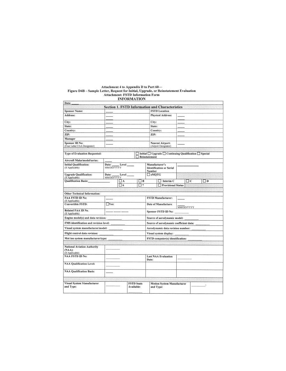
439
Federal Aviation Administration, DOT
Pt. 60, App. D
VerDate Sep<11>2014
14:00 Mar 14, 2024
Jkt 262047
PO 00000
Frm 00449
Fmt 8010
Sfmt 8006
Q:\14\14V2.TXT
PC31
ER09MY08.055</GPH>
aworley on LAPBH6H6L3 with DISTILLER
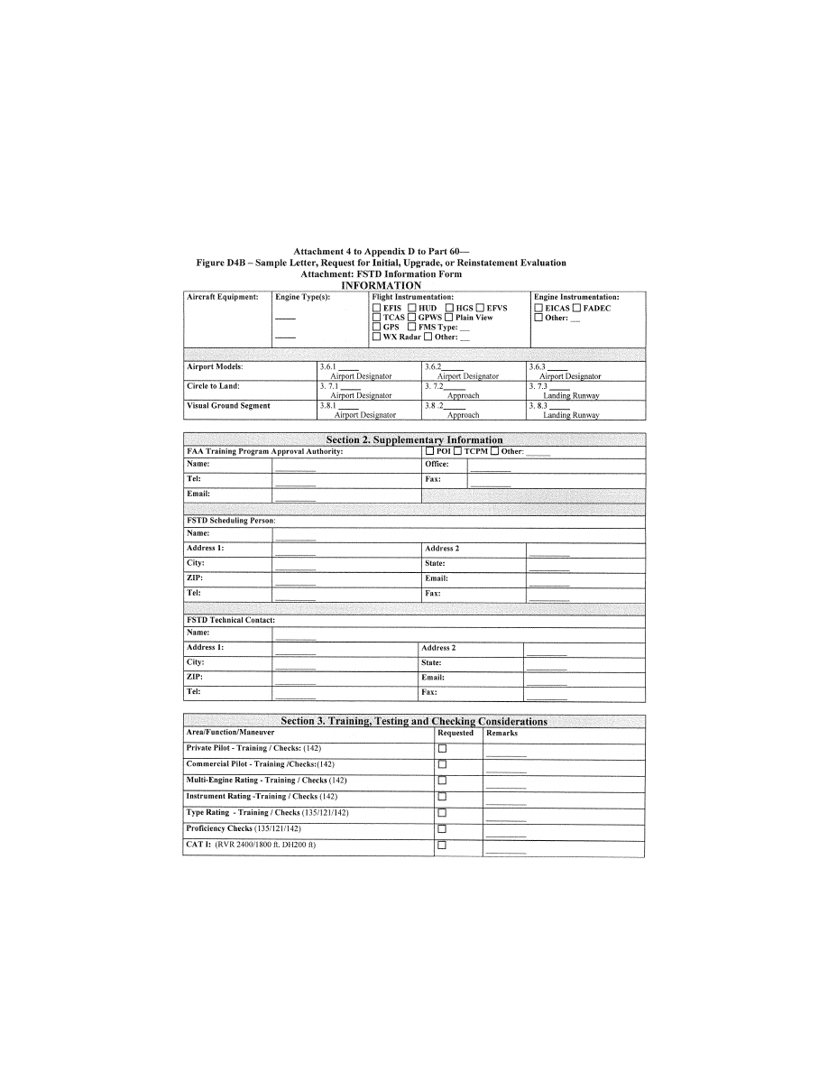
440
14 CFR Ch. I (1–1–24 Edition)
Pt. 60, App. D
VerDate Sep<11>2014
14:00 Mar 14, 2024
Jkt 262047
PO 00000
Frm 00450
Fmt 8010
Sfmt 8006
Q:\14\14V2.TXT
PC31
ER09MY08.056</GPH>
aworley on LAPBH6H6L3 with DISTILLER

441
Federal Aviation Administration, DOT
Pt. 60, App. D
A
TTACHMENT
4
TO
A
PPENDIX
D
TO
P
ART
60—
F
IGURE
D4C—S
AMPLE
L
ETTER OF
C
OMPLIANCE
I
NFORMATION
VerDate Sep<11>2014
14:00 Mar 14, 2024
Jkt 262047
PO 00000
Frm 00451
Fmt 8010
Sfmt 8002
Q:\14\14V2.TXT
PC31
ER09MY08.057</GPH>
aworley on LAPBH6H6L3 with DISTILLER

442
14 CFR Ch. I (1–1–24 Edition)
Pt. 60, App. D
A
TTACHMENT
4
TO
A
PPENDIX
D
TO
P
ART
60—
F
IGURE
D4D—S
AMPLE
Q
UALIFICATION
T
EST
G
UIDE
C
OVER
P
AGE
I
NFORMATION
VerDate Sep<11>2014
14:00 Mar 14, 2024
Jkt 262047
PO 00000
Frm 00452
Fmt 8010
Sfmt 8002
Q:\14\14V2.TXT
PC31
ER09DE22.123</GPH>
ER09DE22.124</GPH>
aworley on LAPBH6H6L3 with DISTILLER
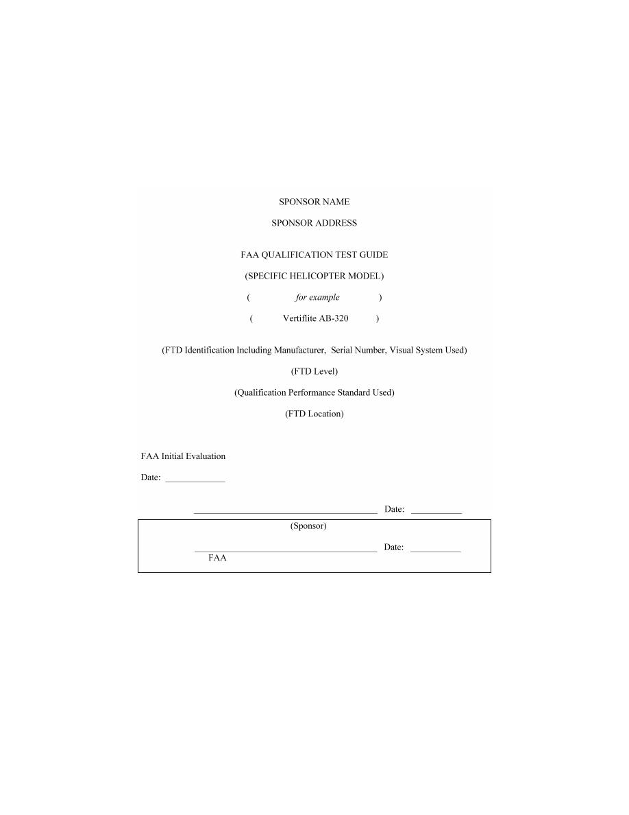
443
Federal Aviation Administration, DOT
Pt. 60, App. D
A
TTACHMENT
4
TO
A
PPENDIX
D
TO
P
ART
60—
F
IGURE
D4E—S
AMPLE
S
TATEMENT OF
Q
UALI
-
FICATION
—C
ERTIFICATE
I
NFORMATION
VerDate Sep<11>2014
14:00 Mar 14, 2024
Jkt 262047
PO 00000
Frm 00453
Fmt 8010
Sfmt 8002
Q:\14\14V2.TXT
PC31
ER09DE22.125</GPH>
ER09DE22.126</GPH>
aworley on LAPBH6H6L3 with DISTILLER

444
14 CFR Ch. I (1–1–24 Edition)
Pt. 60, App. D
VerDate Sep<11>2014
14:00 Mar 14, 2024
Jkt 262047
PO 00000
Frm 00454
Fmt 8010
Sfmt 8006
Q:\14\14V2.TXT
PC31
ER09DE22.130</GPH>
aworley on LAPBH6H6L3 with DISTILLER
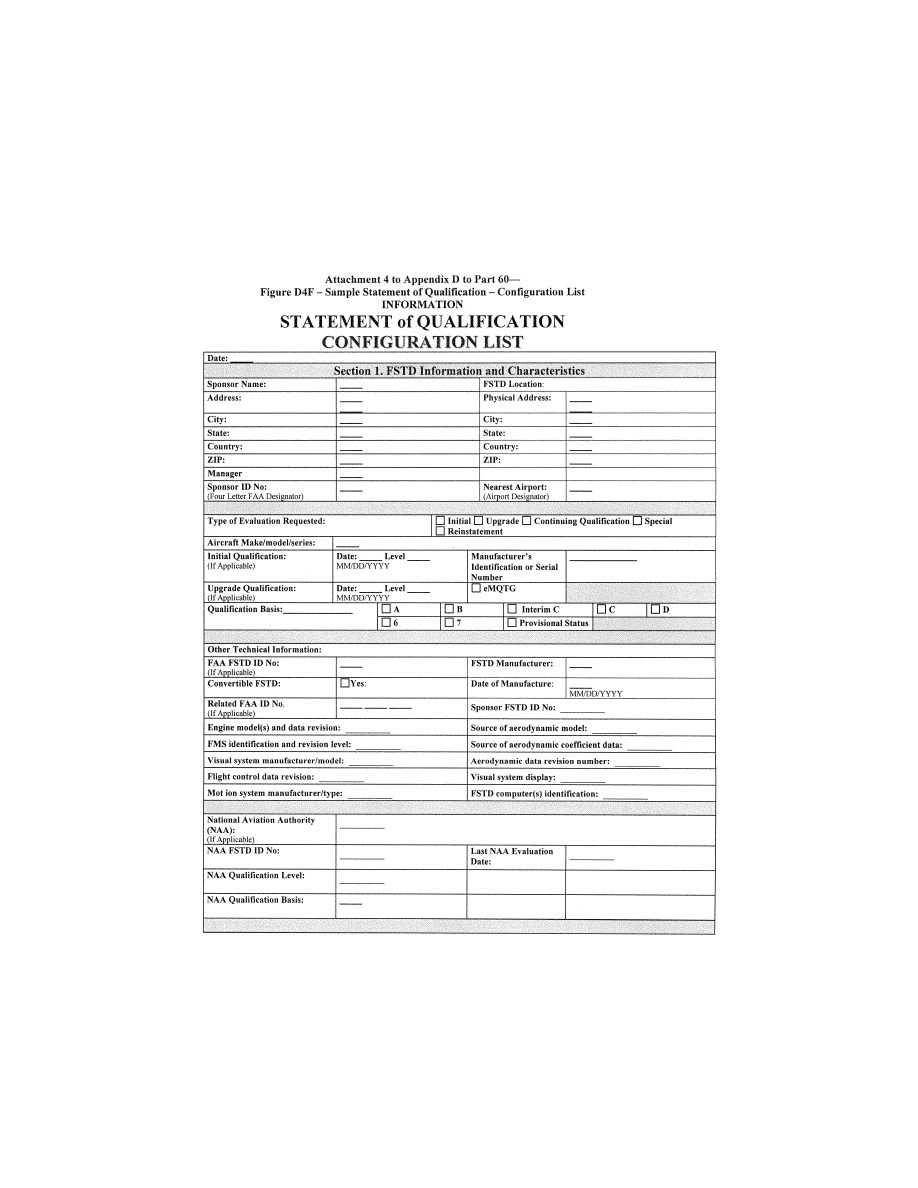
445
Federal Aviation Administration, DOT
Pt. 60, App. D
VerDate Sep<11>2014
14:00 Mar 14, 2024
Jkt 262047
PO 00000
Frm 00455
Fmt 8010
Sfmt 8006
Q:\14\14V2.TXT
PC31
ER09MY08.061</GPH>
aworley on LAPBH6H6L3 with DISTILLER
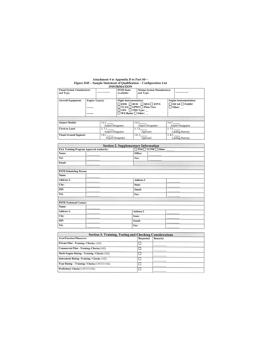
446
14 CFR Ch. I (1–1–24 Edition)
Pt. 60, App. D
VerDate Sep<11>2014
14:00 Mar 14, 2024
Jkt 262047
PO 00000
Frm 00456
Fmt 8010
Sfmt 8006
Q:\14\14V2.TXT
PC31
ER09MY08.062</GPH>
aworley on LAPBH6H6L3 with DISTILLER
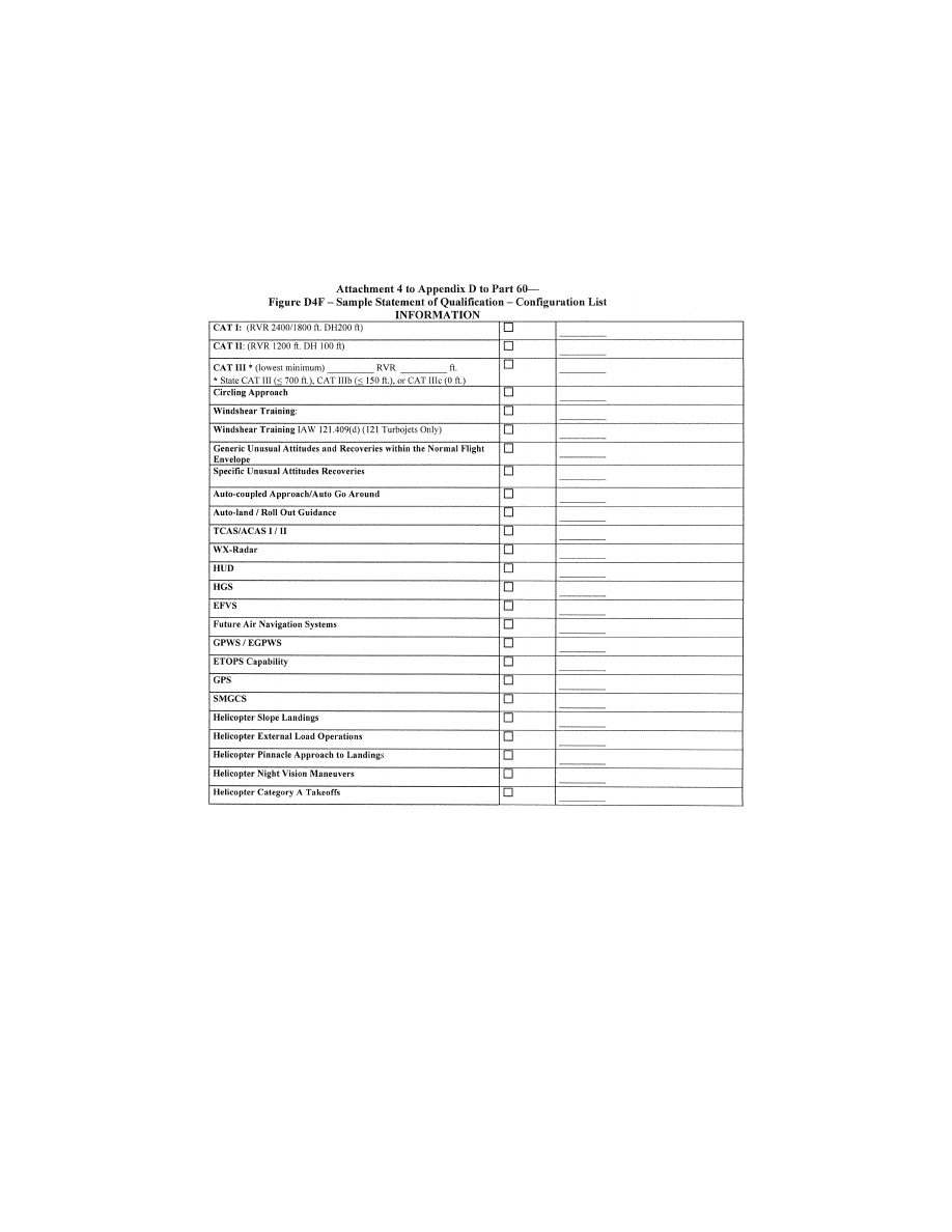
447
Federal Aviation Administration, DOT
Pt. 60, App. D
VerDate Sep<11>2014
14:00 Mar 14, 2024
Jkt 262047
PO 00000
Frm 00457
Fmt 8010
Sfmt 8006
Q:\14\14V2.TXT
PC31
ER09MY08.063</GPH>
aworley on LAPBH6H6L3 with DISTILLER

448
14 CFR Ch. I (1–1–24 Edition)
Pt. 60, App. D
A
TTACHMENT
4
TO
A
PPENDIX
D
TO
P
ART
60—F
IGURE
D4H [R
ESERVED
]
VerDate Sep<11>2014
14:00 Mar 14, 2024
Jkt 262047
PO 00000
Frm 00458
Fmt 8010
Sfmt 8026
Q:\14\14V2.TXT
PC31
ER09MY08.064</GPH>
aworley on LAPBH6H6L3 with DISTILLER

449
Federal Aviation Administration, DOT
Pt. 60, App. E
[Doc. No. FAA–2002–12461, 73 FR 26490, May 9, 2008, as amended by Amdt. 60–6, 83 FR 30276,
June 27, 2018; Docket No. FAA–2022–1355, Amdt. No. 60–7, 87 FR 75832, Dec. 9, 2022]
A
PPENDIX
E
TO
P
ART
60—Q
UALIFICATION
P
ERFORMANCE
S
TANDARDS
FOR
Q
UALITY
M
ANAGEMENT
S
YSTEMS FOR
F
LIGHT
S
IMULATION
T
RAINING
D
E
-
VICES
llllllllllllllllllllllll
B
EGIN
QPS R
EQUIREMENTS
a. Not later than May 30, 2010, each current
sponsor of an FSTD must submit to the re-
sponsible Flight Standards office a proposed
Quality Management System (QMS) program
as described in this appendix. The respon-
sible Flight Standards office will notify the
sponsor of the acceptability of the program,
including any required adjustments. Within 6
months of the notification of acceptability,
the sponsor must implement the program,
conduct internal audits, make required pro-
gram adjustments as a result of any internal
audit, and schedule the responsible Flight
Standards office initial audit.
b. First-time FSTD sponsors must submit
to the responsible Flight Standards office
the proposed QMS program no later than 120
days before the initial FSTD evaluation. The
responsible Flight Standards office will no-
tify the sponsor of the acceptability of the
program, including any required adjust-
ments. Within 6 months of the notification
of acceptability, the sponsor must imple-
ment the program, conduct internal audits,
make required program adjustments as a re-
sult of any internal audit, and schedule the
responsible Flight Standards office initial
audit.
c. The Director of Operations for a Part 119
certificate holder, the Chief Instructor for a
Part 141 certificate holder, or the equivalent
for a Part 142 or Flight Engineer School
sponsor must designate a Management Rep-
resentative (MR) who has the authority to
establish and modify the sponsor’s policies,
practices, and procedures regarding the QMS
program for the recurring qualification and
the daily use of each FSTD.
d. The minimum content required for an
acceptable QMS is found in Table E1. The
policies, processes, or procedures described
in this table must be maintained in a Qual-
ity Manual and will serve as the basis for the
following:
(1) The sponsor-conducted initial and re-
curring periodic assessments;
VerDate Sep<11>2014
14:00 Mar 14, 2024
Jkt 262047
PO 00000
Frm 00459
Fmt 8010
Sfmt 8002
Q:\14\14V2.TXT
PC31
ER09MY08.066</GPH>
aworley on LAPBH6H6L3 with DISTILLER

450
14 CFR Ch. I (1–1–24 Edition)
Pt. 60, App. E
(2) The responsible Flight Standards office-
conducted initial and recurring periodic as-
sessments; and
(3) The continuing surveillance and anal-
ysis by the responsible Flight Standards of-
fice of the sponsor’s performance and effec-
tiveness in providing a satisfactory FSTD for
use on a regular basis.
e. The sponsor must conduct assessments
of its QMS program in segments. The seg-
ments will be established by the responsible
Flight Standards office at the initial assess-
ment, and the interval for the segment as-
sessments will be every 6 months. The inter-
vals for the segment assessments may be ex-
tended beyond 6 months as the QMS program
matures, but will not be extended beyond 12
months. The entire QMS program must be
assessed every 24 months.
f. The periodic assessments conducted by
the responsible Flight Standards office will
be conducted at intervals not less than once
every 24 months, and include a comprehen-
sive review of the QMS program. These re-
views will be conducted more frequently if
warranted.
E
ND
QPS R
EQUIREMENTS
llllllllllllllllllllllll
B
EGIN
I
NFORMATION
g. An example of a segment assessment—
At the initial QMS assessment, the respon-
sible Flight Standards office will divide the
QMS program into segments (e.g., 6 separate
segments). There must be an assessment of a
certain number of segments every 6 months
(i.e., segments 1 and 2 at the end of the first
6 month period; segments 3 and 4 at the end
of the second 6 month period (or one year);
and segments 5 and 6 at the end of the third
6 month period (or 18 months). As the pro-
gram matures, the interval between assess-
ments may be extended to 12 months (e.g.,
segments 1, 2, and 3 at the end of the first
year; and segments 4, 5, and 6 at the end of
the second year). In both cases, the entire
QMS program is assessed at least every 24
months.
h. The following materials are presented to
assist sponsors in preparing for an respon-
sible Flight Standards office evaluation of
the QMS program. The sample documents in-
clude:
(1) The desk assessment tool for initial
evaluation of the required elements of a
QMS program.
(2) The on-site assessment tool for initial
and continuing evaluation of the required
elements of a QMS program.
(3) An Element Assessment Table that de-
scribes the circumstances that exist to war-
rant a finding of ‘‘non-compliance,’’ or ‘‘non-
conformity’’; ‘‘partial compliance,’’ or ‘‘par-
tial conformity’’; and ‘‘acceptable compli-
ance,’’ or ‘‘acceptable conformity.’’
(4) A sample Continuation Sheet for addi-
tional comments that may be added by the
sponsor or the responsible Flight Standards
office during a QMS evaluation.
(5) A sample Sponsor Checklist to assist
the sponsor in verifying the elements that
comprise the required QMS program.
(6) A table showing the essential functions,
processes, and procedures that relate to the
required QMS components and a cross-ref-
erence to each represented task.
i. Additional Information.
(1) In addition to specifically designated
QMS evaluations, the responsible Flight
Standards office will evaluate the sponsor’s
QMS program as part of regularly scheduled
FSTD continuing qualification evaluations
and no-notice FSTD evaluations, focusing in
part on the effectiveness and viability of the
QMS program and its contribution to the
overall capability of the FSTD to meet the
requirements of this part.
(2) The sponsor or MR may delegate duties
associated with maintaining the qualifica-
tion of the FSTD (e.g., corrective and pre-
ventive maintenance, scheduling and con-
ducting tests or inspections, functional pre-
flight checks) but retain the responsibility
and authority for the day-to-day qualifica-
tion of the FSTD. One person may serve as
the sponsor or MR for more than one FSTD,
but one FSTD may not have more than one
sponsor or MR.
(3) A QMS program may be applicable to
more than one certificate holder (e.g., part
119 and part 142 or two part 119 certificate
holders) and an MR may work for more than
one certificate holder (e.g., part 119 and part
142 or two part 119 certificate holders) as
long as the sponsor’s QMS program require-
ments and the MR requirements are met for
each certificate holder.
j. The FAA does not mandate a specific
QMS program format, but an acceptable
QMS program should contain the following:
(1) A Quality Policy. This is a formal writ-
ten Quality Policy Statement that is a com-
mitment by the sponsor outlining what the
Quality System will achieve.
(2) A MR who has overall authority for
monitoring the on-going qualification of as-
signed FSTDs to ensure that all FSTD quali-
fication issues are resolved as required by
this part. The MR should ensure that the
QMS program is properly implemented and
maintained, and should:
(a) Brief the sponsor’s management on the
qualification processes;
(b) Serve as the primary contact point for
all matters between the sponsor and the re-
sponsible Flight Standards office regarding
the qualification of the assigned FSTDs; and
(c) Oversee the day-to-day quality control.
(3) The system and processes outlined in
the QMS should enable the sponsor to mon-
itor compliance with all applicable regula-
tions and ensure correct maintenance and
VerDate Sep<11>2014
14:00 Mar 14, 2024
Jkt 262047
PO 00000
Frm 00460
Fmt 8010
Sfmt 8002
Q:\14\14V2.TXT
PC31
aworley on LAPBH6H6L3 with DISTILLER

451
Federal Aviation Administration, DOT
Pt. 60, App. E
performance of the FSTD in accordance with
part 60.
(4) A QMS program and a statement ac-
knowledging completion of a periodic review
by the MR should include the following:
(a) A maintenance facility that provides
suitable FSTD hardware and software tests
and maintenance capability.
(b) A recording system in the form of a
technical log in which defects, deferred de-
fects, and development projects are listed,
assigned and reviewed within a specified
time period.
(c) Routine maintenance of the FSTD and
performance of the QTG tests with adequate
staffing to cover FSTD operating periods.
(d) A planned internal assessment schedule
and a periodic review should be used to
verify that corrective action was complete
and effective. The assessor should have ade-
quate knowledge of FSTDs and should be ac-
ceptable to the responsible Flight Standards
office.
(5) The MR should receive Quality System
training and brief other personnel on the
procedures.
E
ND
I
NFORMATION
llllllllllllllllllllllll
T
ABLE
E1—FSTD Q
UALITY
M
ANAGEMENT
S
YSTEM
Entry No.
QPS Requirement
Information
(Reference)
E1.1. ...................
A QMS manual that prescribes the policies, processes, or procedures out-
lined in this table.
§ 60.5(a).
E1.2. ...................
A policy, process, or procedure specifying how the sponsor will identify defi-
ciencies in the QMS.
§ 60.5(b).
E1.3. ...................
A policy, process, or procedure specifying how the sponsor will document
how the QMS program will be changed to address deficiencies.
§ 60.5(b).
E1.4. ...................
A policy, process, or procedure specifying how the sponsor will address pro-
posed program changes (for programs that do not meet the minimum re-
quirements as notified by the responsible Flight Standards office) to the re-
sponsible Flight Standards office and receive approval prior to their imple-
mentation.
§ 60.5(c).
E1.5. ...................
A policy, process, or procedure specifying how the sponsor will document
that at least one FSTD is used within the sponsor’s FAA-approved flight
training program for the aircraft or set of aircraft at least once within the
12-month period following the initial or upgrade evaluation conducted by
the responsible Flight Standards office and at least once within each sub-
sequent 12-month period thereafter.
§ 60. 7(b)(5).
E1.6. ...................
A policy, process, or procedure specifying how the sponsor will document
that at least one FSTD is used within the sponsor’s FAA-approved flight
training program for the aircraft or set of aircraft at least once within the
12-month period following the first continuing qualification evaluation con-
ducted by the responsible Flight Standards office and at least once within
each subsequent 12-month period thereafter.
§ 60.7(b)(6).
E1.7. ...................
A policy, process, or procedure specifying how the sponsor will obtain an an-
nual written statement from a qualified pilot (who has flown the subject air-
craft or set of aircraft during the preceding 12-month period) that the per-
formance and handling qualities of the subject FSTD represents the sub-
ject aircraft or set of aircraft (within the normal operating envelope). Re-
quired only if the subject FSTD is not used in the sponsor’s FAA-approved
flight training program for the aircraft or set of aircraft at least once within
the preceding 12-month period.
§ 60.5(b)(7) and § 60.7(d)(2).
E1.8. ...................
A policy, process, or procedure specifying how independent feedback (from
persons recently completing training, evaluation, or obtaining flight experi-
ence; instructors and check airmen using the FSTD for training, evaluation
or flight experience sessions; and FSTD technicians and maintenance per-
sonnel) will be received and addressed by the sponsor regarding the
FSTD and its operation.
§ 60.9(b)(1).
E1.9. ...................
A policy, process, or procedure specifying how and where the FSTD SOQ
will be posted, or accessed by an appropriate terminal or display, in or ad-
jacent to the FSTD.
§ 60.9(b)(2).
E1.10. .................
A policy, process, or procedure specifying how the sponsor’s management
representative (MR) is selected and identified by name to the responsible
Flight Standards office.
§ 60.9(c) and Appendix E,
paragraph(d).
E1.11. .................
A policy, process, or procedure specifying the MR authority and responsibility
for the following:
§ 60.9(c)(2), (3), and (4).
E1.11.a. ..............
Monitoring the on-going qualification of assigned FSTDs to ensure all matters
regarding FSTD qualification are completed as required by this part.
E1.11.b. ..............
Ensuring that the QMS is properly maintained by overseeing the QMS poli-
cies, practices, or procedures and modifying as necessary.
E1.11.c. ..............
Regularly briefing sponsor’s management on the status of the on-going
FSTD qualification program and the effectiveness and efficiency of the
QMS.
VerDate Sep<11>2014
14:00 Mar 14, 2024
Jkt 262047
PO 00000
Frm 00461
Fmt 8010
Sfmt 8002
Q:\14\14V2.TXT
PC31
aworley on LAPBH6H6L3 with DISTILLER

452
14 CFR Ch. I (1–1–24 Edition)
Pt. 60, App. E
T
ABLE
E1—FSTD Q
UALITY
M
ANAGEMENT
S
YSTEM
—Continued
Entry No.
QPS Requirement
Information
(Reference)
E1.11.d. ..............
Serving as the primary contact point for all matters between the sponsor and
the responsible Flight Standards office regarding the qualification of as-
signed FSTDs.
E1.11.e. ..............
Delegating the MR assigned duties to an individual at each of the sponsor’s
locations, as appropriate.
E1.12. .................
A policy, process, or procedure specifying how the sponsor will: ....................
§ 60.13; QPS Appendices A,
B, C, and D.
E1.12.a. ..............
Ensure that the data made available to the responsible Flight Standards of-
fice (the validation data package) includes the aircraft manufacturer’s flight
test data (or other data approved by the responsible Flight Standards of-
fice) and all relevant data developed after the type certificate was issued
(e.g., data developed in response to an airworthiness directive) if the data
results from a change in performance, handling qualities, functions, or
other characteristics of the aircraft that must be considered for flight crew-
member training, evaluation, or experience requirements.
E1.12.b. ..............
Notify the responsible Flight Standards office within 10 working days of be-
coming aware that an addition to or a revision of the flight related data or
airplane systems related data is available if this data is used to program or
operate a qualified FSTD.
E1.12.c. ..............
Maintain a liaison with the manufacturer of the aircraft being simulated (or
with the holder of the aircraft type certificate for the aircraft being simulated
if the manufacturer is no longer in business), and if appropriate, with the
person who supplied the aircraft data package for the FFS for the pur-
poses of receiving notification of data package changes.
E1.13. .................
A policy, process, or procedure specifying how the sponsor will make avail-
able all special equipment and qualified personnel needed to conduct tests
during initial, continuing qualification, or special evaluations.
§ 60.14.
E1.14. .................
A policy, process, or procedure specifying how the sponsor will submit to the
responsible Flight Standards office a request to evaluate the FSTD for ini-
tial qualification at a specific level and simultaneously request the TPAA
forward a concurring letter to the responsible Flight Standards office; in-
cluding how the MR will use qualified personnel to confirm the following:.
§ 60.15(a)–(d); § 60.15(b);
§ 60.15(b)(i); § 60.15(b)(ii);
§ 60.15(b)(iii).
E1.14.a. ..............
That the performance and handling qualities of the FSTD represent those of
the aircraft or set of aircraft within the normal operating envelope.
E1.14.b. ..............
The FSTD systems and sub-systems (including the simulated aircraft sys-
tems) functionally represent those in the aircraft or set of aircraft.
E1.14.c. ..............
The flight deck represents the configuration of the specific type or aircraft
make, model, and series aircraft being simulated, as appropriate.
E1.15. .................
A policy, process, or procedure specifying how the subjective and objective
tests are completed at the sponsor’s training facility for an initial evaluation.
§ 60.15(e).
E1.16. .................
A policy, process, or procedure specifying how the sponsor will update the
QTG with the results of the FAA-witnessed tests and demonstrations to-
gether with the results of the objective tests and demonstrations after the
responsible Flight Standards office completes the evaluation for initial qual-
ification.
§ 60.15(h).
E1.17. .................
A policy, process, or procedure specifying how the sponsor will make the
MQTG available to the responsible Flight Standards office upon request.
§ 60.15(i).
E1.18. .................
A policy, process, or procedure specifying how the sponsor will apply to the
responsible Flight Standards office for additional qualification(s) to the
SOQ.
§ 60.16(a);
§ 60.16(a)(1)(i); and
§ 60.16(a)(1)(ii).
E1.19. .................
A policy, process, or procedure specifying how the sponsor completes all re-
quired Attachment 2 objective tests each year in a minimum of four evenly
spaced inspections as specified in the appropriate QPS.
§ 60.19(a)(1)
QPS Appendices A, B, C, or
D.
E1.20. .................
A policy, process, or procedure specifying how the sponsor completes and
records a functional preflight check of the FSTD within the preceding 24
hours of FSTD use, including a description of the functional preflight.
§ 60.19(a)(2) QPS Appen-
dices A, B, C, or D.
E1.21. .................
A policy, process, or procedure specifying how the sponsor schedules con-
tinuing qualification evaluations with the responsible Flight Standards office.
§ 60.19(b)(2).
E1.22. .................
A policy, process, or procedure specifying how the sponsor ensures that the
FSTD has received a continuing qualification evaluation at the interval de-
scribed in the MQTG.
§ 60.19(b)(5)–(6).
E1.23. .................
A policy, process, or procedure describing how discrepancies are recorded in
the FSTD discrepancy log, including.
§ 60.19(c);
§ 60.19(c)(2)(i);
§ 60.19(c)(2)(ii).
E1.23.a. ..............
A description of how the discrepancies are entered and maintained in the log
until corrected.
E1.23.b. ..............
A description of the corrective action taken for each discrepancy, the identity
of the individual taking the action, and the date that action is taken.
VerDate Sep<11>2014
14:00 Mar 14, 2024
Jkt 262047
PO 00000
Frm 00462
Fmt 8010
Sfmt 8002
Q:\14\14V2.TXT
PC31
aworley on LAPBH6H6L3 with DISTILLER

453
Federal Aviation Administration, DOT
Pt. 60, App. E
T
ABLE
E1—FSTD Q
UALITY
M
ANAGEMENT
S
YSTEM
—Continued
Entry No.
QPS Requirement
Information
(Reference)
E1.24. .................
A policy, process, or procedure specifying how the discrepancy log is kept in
a form and manner acceptable to the Administrator and kept in or adjacent
to the FSTD. (An electronic log that may be accessed by an appropriate
terminal or display in or adjacent to the FSTD is satisfactory.).
§ 60.19(c)(2)(iii).
E1.25. .................
A policy, process, or procedure that requires each instructor, check airman,
or representative of the Administrator conducting training, evaluation, or
flight experience, and each person conducting the preflight inspection, who
discovers a discrepancy, including any missing, malfunctioning, or inoper-
ative components in the FSTD, to write or cause to be written a description
of that discrepancy into the discrepancy log at the end of the FSTD pre-
flight or FSTD use session.
§ 60.20.
E1.26. .................
A policy, process, or procedure specifying how the sponsor will apply for ini-
tial qualification based on the final aircraft data package approved by the
aircraft manufacturer if operating an FSTD based on an interim qualifica-
tion.
§ 60.21(c).
E1.27. .................
A policy, process, or procedure specifying how the sponsor determines
whether an FSTD change qualifies as a modification as defined in § 60.23.
§ 60.23(a)(1)–(2).
E1.28. .................
A policy, process, or procedure specifying how the sponsor will ensure the
FSTD is modified in accordance with any FSTD Directive regardless of the
original qualification basis.
§ 60.23(b).
E1.29. .................
A policy, process, or procedure specifying how the sponsor will notify the re-
sponsible Flight Standards office and TPAA of their intent to use a modi-
fied FSTD and to ensure that the modified FSTD will not be used prior to:.
§ 60.23(c)(1)(i),(ii), and (iv).
E1.29.a. ..............
Twenty-one days since the sponsor notified the responsible Flight Standards
office and the TPAA of the proposed modification and the sponsor has not
received any response from either the responsible Flight Standards office
or the TPAA; or.
E1.29.b. ..............
Twenty-one days since the sponsor notified the responsible Flight Standards
office and the TPAA of the proposed modification and one has approved
the proposed modification and the other has not responded; or.
E1.29.c. ..............
The FSTD successfully completing any evaluation the responsible Flight
Standards office may require in accordance with the standards for an eval-
uation for initial qualification or any part thereof before the modified FSTD
is placed in service.
E1.30 ..................
A policy, process, or procedure specifying how, after an FSTD modification is
approved by the responsible Flight Standards office, the sponsor will:
§ 60.23(d)–(e).
E1.30.a. ..............
Post an addendum to the SOQ until as the responsible Flight Standards of-
fice issues a permanent, updated SOQ.
E1.30.b. ..............
Update the MQTG with current objective test results and appropriate objec-
tive data for each affected objective test or other MQTG section affected
by the modification.
E1.30.c. ..............
File in the MQTG the requirement from the responsible Flight Standards of-
fice to make the modification and the record of the modification completion.
E1.31. .................
A policy, process, or procedure specifying how the sponsor will track the
length of time a component has been missing, malfunctioning, or inoper-
ative (MMI), including:.
§ 60.25(b)–(c), and
QPS Appendices
A, B, C, or D.
E1.31.a. ..............
How the sponsor will post a list of MMI components in or adjacent to the
FSTD.
E1.31.b. ..............
How the sponsor will notify the responsible Flight Standards office if the MMI
has not been repaired or replaced within 30 days.*.
E1.32. .................
A policy, process, or procedure specifying how the sponsor will notify the re-
sponsible Flight Standards office and how the sponsor will seek requali-
fication of the FSTD if the FSTD is moved and reinstalled in a different lo-
cation.
§ 60.27(a)(3).
E1.33. .................
A policy, process, or procedure specifying how the sponsor will maintain con-
trol of the following: (The sponsor must specify how these records are
maintained in plain language form or in coded form; but if the coded form
is used, the sponsor must specify how the preservation and retrieval of in-
formation will be conducted.).
§ 60.31.
E1.33.a. ..............
The MQTG and each amendment.
E1.33.b. ..............
A record of all FSTD modifications required by this part since the issuance of
the original SOQ.
E1.33.c. ..............
Results of the qualification evaluations (initial and each upgrade) since the
issuance of the original SOQ.
E1.33.d. ..............
Results of the objective tests conducted in accordance with this part for a pe-
riod of 2 years.
E1.33.e. ..............
Results of the previous three continuing qualification evaluations, or the con-
tinuing qualification evaluations from the previous 2 years, whichever cov-
ers a longer period..
E1.33.f. ...............
Comments obtained in accordance with § 60.9(b);.
VerDate Sep<11>2014
14:00 Mar 14, 2024
Jkt 262047
PO 00000
Frm 00463
Fmt 8010
Sfmt 8002
Q:\14\14V2.TXT
PC31
aworley on LAPBH6H6L3 with DISTILLER

454
14 CFR Ch. I (1–1–24 Edition)
Pt. 60, App. F
T
ABLE
E1—FSTD Q
UALITY
M
ANAGEMENT
S
YSTEM
—Continued
Entry No.
QPS Requirement
Information
(Reference)
E1.33.g. ..............
A record of all discrepancies entered in the discrepancy log over the pre-
vious 2 years, including the following:
E1.33.g.1. ...........
A list of the components or equipment that were or are missing, malfunc-
tioning, or inoperative.
E1.33.g.2. ...........
The action taken to correct the discrepancy.
E1.33.g.3. ...........
The date the corrective action was taken.
E1.33.g.4. ...........
The identity of the person determining that the discrepancy has been cor-
rected..
* Note: If the sponsor has an approved discrepancy prioritization system, this item is satisfied by describing how discrepancies
are prioritized, what actions are taken, and how the sponsor will notify the responsible Flight Standards office if the MMI has not
been repaired or replaced within the specified timeframe.
[Doc. No. FAA–2002–12461, 73 FR 26490, May 9, 2008, as amended by Docket No. FAA–2022–1355,
Amdt. No. 60–7, 87 FR 75842, Dec. 9, 2022]
A
PPENDIX
F
TO
P
ART
60—D
EFINITIONS
AND
A
BBREVIATIONS
FOR
F
LIGHT
S
IMULATION
T
RAINING
D
EVICES
llllllllllllllllllllllll
B
EGIN
I
NFORMATION
1. S
OME OF THE DEFINITIONS PRESENTED BELOW
ARE REPEATED FROM THE DEFINITIONS FOUND
IN
14 CFR
PART
1,
AS
INDICATED
PAR
-
ENTHETICALLY
E
ND
I
NFORMATION
llllllllllllllllllllllll
B
EGIN
QPS R
EQUIREMENTS
2. D
EFINITIONS
1st Segment—the portion of the takeoff pro-
file from liftoff to gear retraction.
2nd Segment—the portion of the takeoff
profile from after gear retraction to initial
flap/slat retraction.
3rd Segment—the portion of the takeoff pro-
file after flap/slat retraction is complete.
Aircraft Data Package—a combination of
the various types of data used to design, pro-
gram, manufacture, modify, and test the
FSTD.
Airspeed—calibrated airspeed unless other-
wise specified and expressed in terms of nau-
tical miles per hour (knots).
Airport Model—
Class I. Whether modeling real world or fic-
tional airports (or landing areas for heli-
copters), these airport models (or landing
areas for helicopters) are those that meet
the requirements of Table A3B or C3B, found
in attachment 2 of Appendix A or C, as ap-
propriate, are evaluated by the responsible
Flight Standards office, and are listed on the
SOQ.
Class II. Whether modeling real world or
fictional airports (or landing areas for heli-
copters), these airport models (or landing
areas for helicopters) are those models that
are in excess of those used for simulator
qualification at a specified level. The FSTD
sponsor is responsible for determining that
these models meet the requirements set out
in Table A3C or C3C, found in attachment 2
of Appendix A or C, as appropriate.
Class III. This is a special class of airport
model (or landing area for helicopters), used
for specific purposes, and includes models
that may be incomplete or inaccurate when
viewed without restriction, but when appro-
priate limits are applied (e.g., ‘‘valid for use
only in visibility conditions less than
1
⁄
2
stat-
ute mile or RVR2400 feet,’’ ‘‘valid for use
only for approaches to Runway 22L and
22R’’), those features that may be incomplete
or inaccurate may not be able to be recog-
nized as such by the crewmember being
trained, tested, or checked. Class III airport
models used for training, testing, or check-
ing activities under this Chapter requires the
certificate holder to submit to the TPAA an
appropriate analysis of the skills, knowl-
edge, and abilities necessary for competent
performance of the task(s) in which this par-
ticular model is to be used, and requires
TPAA acceptance of each Class III model.
Altitude—pressure altitude (meters or feet)
unless specified otherwise.
Angle of Attack—the angle between the air-
plane longitudinal axis and the relative wind
vector projected onto the airplane plane of
symmetry.
Automatic Testing—FSTD testing where all
stimuli are under computer control.
Bank—the airplane attitude with respect
to or around the longitudinal axis, or roll
angle (degrees).
Breakout—the force required at the pilot’s
primary controls to achieve initial move-
ment of the control position.
VerDate Sep<11>2014
14:00 Mar 14, 2024
Jkt 262047
PO 00000
Frm 00464
Fmt 8010
Sfmt 8002
Q:\14\14V2.TXT
PC31
aworley on LAPBH6H6L3 with DISTILLER

455
Federal Aviation Administration, DOT
Pt. 60, App. F
Certificate Holder—a person issued a certifi-
cate under parts 119, 141, or 142 of this chap-
ter or a person holding an approved course of
training for flight engineers in accordance
with part 63 of this chapter.
Closed Loop Testing—a test method where
the input stimuli are generated by control-
lers that drive the FSTD to follow a pre-de-
fined target response.
Computer Controlled Aircraft—an aircraft
where all pilot inputs to the control surfaces
are transferred and augmented by com-
puters.
Confined Area (helicopter operations)—an
area where the flight of the helicopter is lim-
ited in some direction by terrain or the pres-
ence of natural or man-made obstructions
(e.g., a clearing in the woods, a city street,
or a road bordered by trees or power lines are
regarded as confined areas).
Control Sweep—movement of the appro-
priate pilot controller from neutral to an ex-
treme limit in one direction (Forward, Aft,
Right, or Left), a continuous movement back
through neutral to the opposite extreme po-
sition, and then a return to the neutral posi-
tion.
Convertible FSTD—an FSTD in which hard-
ware and software can be changed so that the
FSTD becomes a replica of a different model,
usually of the same type aircraft. The same
FSTD platform, flight deck shell, motion
system, visual system, computers, and pe-
ripheral equipment can be used in more than
one simulation.
Critical Engine Parameter—the parameter
that is the most accurate measure of propul-
sive force.
Deadband—the amount of movement of the
input for a system for which there is no reac-
tion in the output or state of the system ob-
served.
Distance—the length of space between two
points, expressed in terms of nautical miles
unless otherwise specified.
Discrepancy—as used in this part, an aspect
of the FSTD that is not correct with respect
to the aircraft being simulated. This in-
cludes missing, malfunctioning, or inoper-
ative components that are required to be
present and operate correctly for training,
evaluation, and experience functions to be
creditable. It also includes errors in the doc-
umentation used to support the FSTD (e.g.,
MQTG errors, information missing from the
MQTG, or required statements from appro-
priately qualified personnel).
Downgrade—a permanent change in the
qualification level of an FSTD to a lower
level.
Driven—a test method where the input
stimulus or variable is positioned by auto-
matic means, usually a computer input.
Electronic Copy of the MQTG—an electronic
copy of the MQTG provided by an electronic
scan presented in a format, acceptable to the
responsible Flight Standards office.
Electronic Master Qualification Test Guide—
an electronic version of the MQTG (eMQTG),
where all objective data obtained from air-
plane testing, or another approved source,
together with correlating objective test re-
sults obtained from the performance of the
FSTD and a description of the equipment
necessary to perform the evaluation for the
initial and the continuing qualification eval-
uations is stored, archived, or presented in
either reformatted or digitized electronic
format.
Engine—as used in this part, the appliance
or structure that supplies propulsive force
for movement of the aircraft: i.e., The tur-
bine engine for turbine powered aircraft; the
turbine engine and propeller assembly for
turbo-propeller powered aircraft; and the re-
ciprocating engine and propeller assembly
for reciprocating engine powered aircraft.
For purposes of this part, engine failure is
the failure of either the engine or propeller
assembly to provide thrust higher than idle
power thrust due to a failure of either the
engine or the propeller assembly.
Evaluation—with respect to an individual,
the checking, testing, or review associated
with flight crewmember qualification, train-
ing, and certification under parts 61, 63, 121,
or 135 of this chapter. With respect to an
FSTD, the qualification activities for the de-
vice (e.g., the objective and subjective tests,
the inspections, or the continuing qualifica-
tion evaluations) associated with the re-
quirements of this part.
Fictional Airport—a visual model of an air-
port that is a collection of ‘‘non-real world’’
terrain, instrument approach procedures,
navigation aids, maps, and visual modeling
detail sufficient to enable completion of an
Airline Transport Pilot Certificate or Type
Rating.
Flight Experience—recency of flight experi-
ence for landing credit purposes.
Flight Simulation Training Device (FSTD)—a
full flight simulator (FFS) or a flight train-
ing device (FTD). (Part 1)
Flight Test Data—(a subset of objective
data) aircraft data collected by the aircraft
manufacturer or other acceptable data sup-
plier during an aircraft flight test program.
Flight Training Device (FTD)—a replica of
aircraft instruments, equipment, panels, and
controls in an open flight deck area or an en-
closed aircraft flight deck replica. It in-
cludes the equipment and computer pro-
grams necessary to represent aircraft (or set
of aircraft) operations in ground and flight
conditions having the full range of capabili-
ties of the systems installed in the device as
described in part 60 of this chapter and the
qualification performance standard (QPS) for
a specific FTD qualification level. (Part 1)
Free Response—the response of the FSTD
after completion of a control input or dis-
turbance.
VerDate Sep<11>2014
14:00 Mar 14, 2024
Jkt 262047
PO 00000
Frm 00465
Fmt 8010
Sfmt 8002
Q:\14\14V2.TXT
PC31
aworley on LAPBH6H6L3 with DISTILLER

456
14 CFR Ch. I (1–1–24 Edition)
Pt. 60, App. F
Frozen—a test condition where one or more
variables are held constant with time.
FSTD Approval—the extent to which an
FSTD may be used by a certificate holder as
authorized by the FAA.
FSTD Directive—a document issued by the
FAA to an FSTD sponsor requiring a modi-
fication to the FSTD due to a safety-of-flight
issue and amending the qualification basis
for the FSTD.
FSTD Latency—the additional time for the
FSTD to respond to input that is beyond the
response time of the aircraft.
FSTD Performance—the overall perform-
ance of the FSTD, including aircraft per-
formance (e.g., thrust/drag relationships,
climb, range) and flight and ground han-
dling.
Full Flight Simulator (FFS)—a replica of a
specific type, make, model, or series aircraft.
It includes the equipment and computer pro-
grams necessary to represent aircraft oper-
ations in ground and flight conditions, a vis-
ual system providing an out-of-the-flight
deck view, a system that provides cues at
least equivalent to those of a three-degree-
of-freedom motion system, and has the full
range of capabilities of the systems installed
in the device as described in part 60 of this
chapter and the QPS for a specific FFS qual-
ification level. (Part 1)
Gate Clutter—the static and moving ground
traffic (e.g., other airplanes; tugs; power or
baggage carts; fueling, catering, or cargo
trucks; pedestrians) presented to pose a po-
tential conflict with the simulated aircraft
during ground operations around the point
where the simulated airplane is to be parked
between flights
Generic Airport Model—a Class III visual
model that combines correct navigation aids
for a real world airport with a visual model
that does not depict that same airport.
Grandfathering—as used in this part, the
practice of assigning a qualification basis for
an FSTD based on the period of time during
which a published set of standards governed
the requirements for the initial and con-
tinuing qualification of FSTDs. Each FSTD
manufactured during this specified period of
time is ‘‘grandfathered’’ or held to the stand-
ards that were in effect during that time pe-
riod. The grandfathered standards remain
applicable to each FSTD manufactured dur-
ing the stated time period regardless of any
subsequent modification to those standards
and regardless of the sponsor, as long as the
FSTD remains qualified or is maintained in
a non-qualified status in accordance with the
specific requirements and time periods pre-
scribed in this part.
Gross Weight—For objective test purposes:
Basic Operating Weight (BOW)—the empty
weight of the aircraft plus the weight of the
following: Normal oil quantity; lavatory
servicing fluid; potable water; required crew-
members and their baggage; and emergency
equipment.
Light Gross Weight—a weight chosen by the
sponsor or data provider that is not more
than 120% of the BOW of the aircraft being
simulated or the minimum practical oper-
ating weight of the test aircraft.
Medium Gross Weight—a weight chosen by
the sponsor or data provider that is within
10% of the average of the numerical values of
the BOW and the maximum certificated
gross weight.
Near Maximum Gross Weight—a weight cho-
sen by the sponsor or data provider that is
not less than the BOW of the aircraft being
simulated plus 80% of the difference between
the maximum certificated gross weight (ei-
ther takeoff weight or landing weight, as ap-
propriate for the test) and the BOW.
Ground Effect—the change in aerodynamic
characteristics due to of the change in the
airflow past the aircraft caused by the prox-
imity of the earth’s surface to the airplane.
Hands Off—a test maneuver conducted
without pilot control inputs.
Hands On—a test maneuver conducted with
pilot control inputs as required.
Heave—FSTD movement with respect to or
along the vertical axis.
Height—the height above ground level (or
AGL) expressed in meters or feet.
‘‘In Use’’ Runway—as used in this part, the
runway that is currently selected, able to be
used for takeoffs and landings, and has the
surface lighting and markings required by
this part. Also known as the ‘‘active’’ run-
way.
Integrated Testing—testing of the FSTD so
that all aircraft system models are active
and contribute appropriately to the results.
With integrated testing, none of the models
used are substituted with models or other al-
gorithms intended for testing only.
Irreversible Control System—a control sys-
tem where movement of the control surface
will not backdrive the pilot’s control on the
flight deck.
Locked—a test condition where one or more
variables are held constant with time.
Manual Testing—FSTD testing conducted
without computer inputs except for initial
setup, and all modules of the simulation are
active.
Master Qualification Test Guide (MQTG)—
the FAA-approved Qualification Test Guide
with the addition of the FAA-witnessed test
results, applicable to each individual FSTD.
Medium—the normal operational weight for
a given flight segment.
Near Limiting Performance—the perform-
ance level the operating engine must be re-
quired to achieve to have sufficient power to
land a helicopter after experiencing a single
engine failure during takeoff of a multien-
gine helicopter. The operating engine must
be required to operate within at least 5 per-
cent of the maximum RPM or temperature
VerDate Sep<11>2014
14:00 Mar 14, 2024
Jkt 262047
PO 00000
Frm 00466
Fmt 8010
Sfmt 8002
Q:\14\14V2.TXT
PC31
aworley on LAPBH6H6L3 with DISTILLER

457
Federal Aviation Administration, DOT
Pt. 60, App. F
limits of the gas turbine or power turbine, or
operate within at least 5 percent of the max-
imum drive train torque limits. Near lim-
iting performance is based on the existing
combination of density altitude, tempera-
ture, and helicopter gross weight.
Nominal—the normal operating configura-
tion, atmospheric conditions, and flight pa-
rameters for the specified flight segment.
Non-Normal Control—a term used in ref-
erence to Computer Controlled Aircraft. It is
the state where one or more of the intended
control, augmentation, or protection func-
tions are not fully working. Note: Specific
terms such as ALTERNATE, DIRECT, SEC-
ONDARY, or BACKUP may be used to define
an actual level of degradation.
Normal Control—a term used in reference to
Computer Controlled Aircraft. It is the state
where the intended control, augmentation,
and protection functions are fully working.
Objective Data—quantitative data, accept-
able to the NSPM, used to evaluate the
FSTD.
Objective Test—a quantitative measurement
and evaluation of FSTD performance.
Pitch—the airplane attitude with respect
to, or around, the lateral axis expressed in
degrees.
Power Lever Angle (PLA)—the angle of the
pilot’s primary engine control lever(s) on the
flight deck. This may also be referred to as
THROTTLE or POWER LEVER.
Predicted Data—estimations or extrapo-
lations of existing flight test data or data
from other simulation models using engi-
neering analyses, engineering simulations,
design data, or wind tunnel data.
Protection Functions—systems functions de-
signed to protect an airplane from exceeding
its flight maneuver limitations.
Pulse Input—a step input to a control fol-
lowed by an immediate return to the initial
position.
Qualification Level—the categorization of
an FSTD established by the NSPM based on
the FSTDs demonstrated technical and oper-
ational capabilities as prescribed in this
part.
Qualification Performance Standard (QPS)—
the collection of procedures and criteria used
when conducting objective and subjective
tests, to establish FSTD qualification levels.
The QPS are published in the appendices to
this part, as follows: Appendix A, for Air-
plane Simulators; Appendix B, for Airplane
Flight Training Devices; Appendix C, for Hel-
icopter Simulators; Appendix D, for Heli-
copter Flight Training Devices; Appendix E,
for Quality Management Systems for Flight
Simulation Training Devices; and Appendix
F, for Definitions and Abbreviations for
Flight Simulation Training Devices.
Qualification Test Guide (QTG)—the pri-
mary reference document used for evalu-
ating an aircraft FSTD. It contains test re-
sults, statements of compliance and capa-
bility, the configuration of the aircraft sim-
ulated, and other information for the eval-
uator to assess the FSTD against the appli-
cable regulatory criteria.
Quality Management System (QMS)—a flight
simulation quality-systems that can be used
for external quality-assurance purposes. It is
designed to identify the processes needed, de-
termine the sequence and interaction of the
processes, determine criteria and methods
required to ensure the effective operation
and control of the processes, ensure the
availability of information necessary to sup-
port the operation and monitoring of the
processes, measure, monitor, and analyze the
processes, and implement the actions nec-
essary to achieve planned results.
Real-World Airport—as used in this part in
reference to airport visual models, a com-
puter generated visual depiction of an exist-
ing airport.
Representative—when used as an adjective
in this part, typical, demonstrative, or char-
acteristic of, the feature being described. For
example, ‘‘representative sampling of tests’’
means a sub-set of the complete set of all
tests such that the sample includes one or
more of the tests in each of the major cat-
egories, the results of which provide the
evaluator with an overall understanding of
the performance and handling characteris-
tics of the FSTD.
Reversible Control System—a control system
in which movement of the control surface
will backdrive the pilot’s control on the
flight deck.
Roll—the airplane attitude with respect to,
or around, the longitudinal axis expressed in
degrees.
Set of Aircraft—aircraft that share similar
handling and operating characteristics, simi-
lar operating envelopes, and have the same
number and type of engines or powerplants.
Sideslip Angle—the angle between the rel-
ative wind vector and the airplane plane of
symmetry. (Note: this definition replaces the
current definition of ‘‘sideslip.’’)
Simulation Quality Management System
(SQMS)—the elements of a quality manage-
ment system for FSTD continuing qualifica-
tion.
Snapshot—a presentation of one or more
variables at a given instant of time.
Special Evaluation—an evaluation of the
FSTD for purposes other than initial, up-
grade, or continuing qualification. Cir-
cumstances that may require a special eval-
uation include movement of the FSTD to a
different location, or an update to FSTD
software or hardware that might affect per-
formance or flying qualities.
Sponsor—a certificate holder who seeks or
maintains FSTD qualification and is respon-
sible for the prescribed actions as prescribed
in this part and the QPS for the appropriate
FSTD and qualification level.
VerDate Sep<11>2014
14:00 Mar 14, 2024
Jkt 262047
PO 00000
Frm 00467
Fmt 8010
Sfmt 8002
Q:\14\14V2.TXT
PC31
aworley on LAPBH6H6L3 with DISTILLER

458
14 CFR Ch. I (1–1–24 Edition)
Pt. 60, App. F
Statement of Compliance and Capability
(SOC)—a declaration that a specific require-
ment has been met and explaining how the
requirement was met (e.g., gear modeling ap-
proach, coefficient of friction sources). The
SOC must also describe the capability of the
FSTD to meet the requirement, including
references to sources of information for
showing compliance, rationale to explain
how the referenced material is used, mathe-
matical equations and parameter values
used, and conclusions reached.
Step Input—an abrupt control input held at
a constant value.
Subjective Test—a qualitative assessment of
the performance and operation of the FSTD.
Surge—FSTD movement with respect to or
along the longitudinal axis.
Sway—FSTD movement with respect to or
along the lateral axis.
T
f
—Total time of the flare maneuver.
T
i
—Total time from initial throttle move-
ment until a 10% response of a critical en-
gine parameter.
T
t
—Total time from initial throttle move-
ment to an increase of 90% of go around
power or a decrease of 90% from maximum
take-off power.
Time History—a presentation of the change
of a variable with respect to time.
Training Program Approval Authority
(TPAA)—a person authorized by the Adminis-
trator to approve the aircraft flight training
program in which the FSTD will be used.
Training Restriction—a temporary condition
where an FSTD with missing, malfunc-
tioning, or inoperative (MMI) components
may continue to be used at the qualification
level indicated on its SOQ, but restricted
from completing the tasks for which the cor-
rect function of the MMI component is re-
quired.
Transport Delay or ‘‘Throughput’’—the total
FSTD system processing time required for
an input signal from a pilot primary flight
control until motion system, visual system,
or instrument response. It is the overall time
delay incurred from signal input to output
response. It does not include the char-
acteristic delay of the airplane simulated.
Update—an improvement to or moderniza-
tion of the quality or the accuracy of the
FSTD without affecting the qualification
level of the FSTD.
Upgrade—the improvement or enhance-
ment of an FSTD for the purpose of achiev-
ing a higher qualification level.
Validation Data—objective data used to de-
termine if the FSTD performance is within
the tolerances prescribed in the QPS.
Validation Test—an objective test where
FSTD parameters are compared to the rel-
evant validation data to ensure that the
FSTD performance is within the tolerances
prescribed in the QPS.
Visual Data Base—a display that may in-
clude one or more airport models.
Visual System Response Time—the interval
from a control input to the completion of the
visual display scan of the first video field
containing the resulting different informa-
tion.
Yaw—the airplane attitude with respect to,
or around, the vertical axis expressed in de-
grees.
3. Abbreviations
AFM
Airplane Flight Manual.
AGL
Above Ground Level (meters or feet).
AOA
Angle of Attack (degrees).
APD
Aircrew Program Designee.
CCA
Computer Controlled Aircraft.
cd/m2
candela/meter
2
, 3.4263 candela/m
2
= 1
ft-Lambert.
CFR
Code of Federal Regulations.
cm(s)
centimeter, centimeters.
daN
decaNewtons, one (1) decaNewton = 2.27
pounds.
deg(s)
degree, degrees.
DOF
Degrees-of-freedom.
eMQTG
Electronic Master Qualification
Test Guide.
EPR
Engine Pressure Ratio.
FAA
Federal Aviation Administration
(U.S.).
FATO
Final Approach and Take Off area
fpm
feet per minute.
ft
foot/feet, 1 foot = 0.304801 meters.
ft-Lambert
foot-Lambert, 1 ft-Lambert =
3.4263 candela/m
2
.
g
Acceleration due to Gravity (meters or
feet/sec
2
); 1g = 9.81 m/sec
2
or 32.2 feet/sec
2
.
G/S
Glideslope.
IATA
International Airline Transport Asso-
ciation.
ICAO
International Civil Aviation Organi-
zation.
IGE
In ground effect.
ILS
Instrument Landing System.
IOS
Instructor Operating Station.
IQTG
International Qualification Test
Guide.
km
Kilometers; 1 km = 0.62137 Statute
Miles.
kPa
KiloPascal (Kilo Newton/Meters2). 1 psi
= 6.89476 kPa.
kts
Knots calibrated airspeed unless other-
wise specified, 1 knot = 0.5148 m/sec or 1.689
ft/sec.
lb(s)
pound(s), one (1) pound = 0.44
decaNewton.
LDP
Landing decision point.
MQTG
Master Qualification Test Guide
M,m
Meters, 1 Meter = 3.28083 feet.
Min(s)
Minute, minutes.
MLG
Main Landing Gear.
Mpa
MegaPascals (1 psi = 6894.76 pascals).
ms
millisecond(s).
N
NORMAL CONTROL Used in reference to
Computer Controlled Aircraft.
nm
Nautical Mile(s) 1 Nautical Mile = 6,080
feet.
NN
NON-NORMAL CONTROL Used in ref-
erence to Computer Controlled Aircraft.
VerDate Sep<11>2014
14:00 Mar 14, 2024
Jkt 262047
PO 00000
Frm 00468
Fmt 8010
Sfmt 8002
Q:\14\14V2.TXT
PC31
aworley on LAPBH6H6L3 with DISTILLER

459
Federal Aviation Administration, DOT
Pt. 61
N1
Low Pressure Rotor revolutions per
minute, expressed in percent of maximum.
N2
High Pressure Rotor revolutions per
minute, expressed in percent of maximum.
N3
High Pressure Rotor revolutions per
minute, expressed in percent of maximum.
NWA
Nosewheel Angle (degrees).
OGE
Out of ground effect.
PAPI
Precision Approach Path Indicator
System.
Pf
Impact or Feel Pressure, often expressed
as ‘‘q.’’
PLA
Power Lever Angle.
PLF
Power for Level Flight.
psi
pounds per square inch.
QPS
Qualification Performance Standard.
QTG
Qualification Test Guide.
RAE
Royal Aerospace Establishment.
R/C
Rate of Climb (meters/sec or feet/min).
R/D
Rate of Descent (meters/sec or feet/
min).
REIL
Runway End Identifier Lights.
RVR
Runway Visual Range (meters or
feet).
s
second(s).
sec(s)
second, seconds.
sm
Statute Mile(s) 1 Statute Mile = 5,280
feet.
SMGCS
Surface Movement Guidance and
Control System.
SOC
Statement of Compliance and Capa-
bility.
SOQ
Statement of Qualification.
TIR
Type Inspection Report.
TLOF
Touchdown and Loft Off area.
T/O
Takeoff.
VASI
Visual Approach Slope Indicator Sys-
tem.
VGS
Visual Ground Segment.
V
1
Decision speed.
V
2
Takeoff safety speed.
Vmc
Minimum Control Speed.
Vmca
Minimum Control Speed in the air.
Vmcg
Minimum Control Speed on the
ground.
Vmcl
Minimum Control Speed—Landing.
Vmu
The speed at which the last main
landing gear leaves the ground.
V
R
Rotate Speed.
V
S
Stall Speed or minimum speed in the
stall.
WAT
Weight, Altitude, Temperature.
E
ND
QPS R
EQUIREMENTS
[Doc. No. FAA–2002–12461, 73 FR 26490, May 9,
2008, as amended by Docket No. FAA–2022–
1355, Amdt. No. 60–7, 87 FR 75845, Dec. 9, 2022]
PART 61—CERTIFICATION: PILOTS,
FLIGHT INSTRUCTORS, AND
GROUND INSTRUCTORS
S
PECIAL
F
EDERAL
A
VIATION
R
EGULATION
N
O
.
73
S
PECIAL
F
EDERAL
A
VIATION
R
EGULATION
N
O
.
100–2
Subpart A—General
Sec.
61.1
Applicability and definitions.
61.2
Exercise of Privilege.
61.3
Requirement for certificates, ratings,
and authorizations.
61.4
Qualification and approval of flight
simulators and flight training devices.
61.5
Certificates and ratings issued under
this part.
61.7
Obsolete certificates and ratings.
61.8
Inapplicability of unmanned aircraft
operations.
61.9
[Reserved]
61.11
Expired pilot certificates and
reissuance.
61.13
Issuance of airman certificates, rat-
ings, and authorizations.
61.14
[Reserved]
61.15
Offenses involving alcohol or drugs.
61.16
Refusal to submit to an alcohol test or
to furnish test results.
61.17
Temporary certificate.
61.18
[Reserved]
61.19
Duration of pilot and instructor cer-
tificates and privileges.
61.21
Duration of a Category II and a Cat-
egory III pilot authorization (for other
than part 121 and part 135 use).
61.23
Medical certificates: Requirement and
duration.
61.25
Change of name.
61.27
Voluntary surrender or exchange of
certificate.
61.29
Replacement of a lost or destroyed air-
man or medical certificate or knowledge
test report.
61.31
Type rating requirements, additional
training, and authorization require-
ments.
61.33
Tests: General procedure.
61.35
Knowledge test: Prerequisites and
passing grades.
61.37
Knowledge tests: Cheating or other
unauthorized conduct.
61.39
Prerequisites for practical tests.
61.41
Flight training received from flight
instructors not certificated by the FAA.
61.43
Practical tests: General procedures.
61.45
Practical tests: Required aircraft and
equipment.
61.47
Status of an examiner who is author-
ized by the Administrator to conduct
practical tests.
61.49
Retesting after failure.
61.51
Pilot logbooks.
61.52
Use of aeronautical experience ob-
tained in ultralight vehicles.
61.53
Prohibition on operations during med-
ical deficiency.
61.55
Second-in-command qualifications.
61.56
Flight review.
VerDate Sep<11>2014
14:00 Mar 14, 2024
Jkt 262047
PO 00000
Frm 00469
Fmt 8010
Sfmt 8010
Q:\14\14V2.TXT
PC31
aworley on LAPBH6H6L3 with DISTILLER