4/20/23
AIM
reduced bank angles for all turns including turns in holding, especially at higher altitudes, that may result in
exceeding holding protected airspace. Use of a shallower bank angle will expand both the width and length of
the aircraft track, especially as wind speed increases. If the flight guidance system’s bank angle limit feature is
pilot
−
selectable, a minimum 25 degree bank angle should be selected regardless of altitude unless aircraft
operating limitations specify otherwise and the pilot advises ATC.
(4)
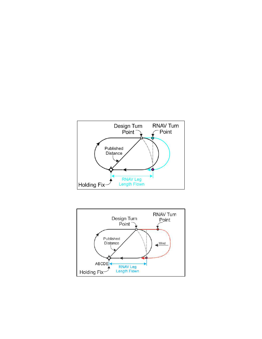
Where a holding distance is published, the turn from the outbound leg begins at the published
distance from the holding fix, thus establishing the design turn point required to remain within protected airspace.
RNAV systems apply a database coded or pilot
−
entered leg distance as a maximum length of the
inbound
leg
to the holding fix. The RNAV system then calculates a turn point from the outbound leg required to achieve this
inbound leg length. This often results in an RNAV
−
calculated turn point on the outbound leg beyond the design
turn point. (See FIG 5
8). With a strong headwind against the outbound leg, RNAV systems may fly up to and
possibly beyond the limits of protected airspace before turning inbound. (See FIG 5
at higher altitudes where wind speeds are greater and ground speed results in a wider holding pattern.
FIG 5
−
3
−
8
RNAV Lateral Guidance and Holding – No Wind
FIG 5
−
3
−
9
RNAV Lateral Guidance and Holding – Effect of Wind
(5)
Some RNAV systems compute the holding pattern based on the aircraft’s altitude and speed at a
point prior to entering the hold. If the indicated airspeed is not reduced to comply with the maximum holding
speed before this point, the computed pattern may exceed the protected airspace. Loading or executing a holding
pattern may result in the speed and time limits applicable to the aircraft’s current altitude being used to define
the holding pattern for RNAV lateral guidance. This may result in an incorrect hold being flown by the RNAV
En Route Procedures
5
−
3
−
27