4/20/23
AIM
FIG 9
−
1
−
5
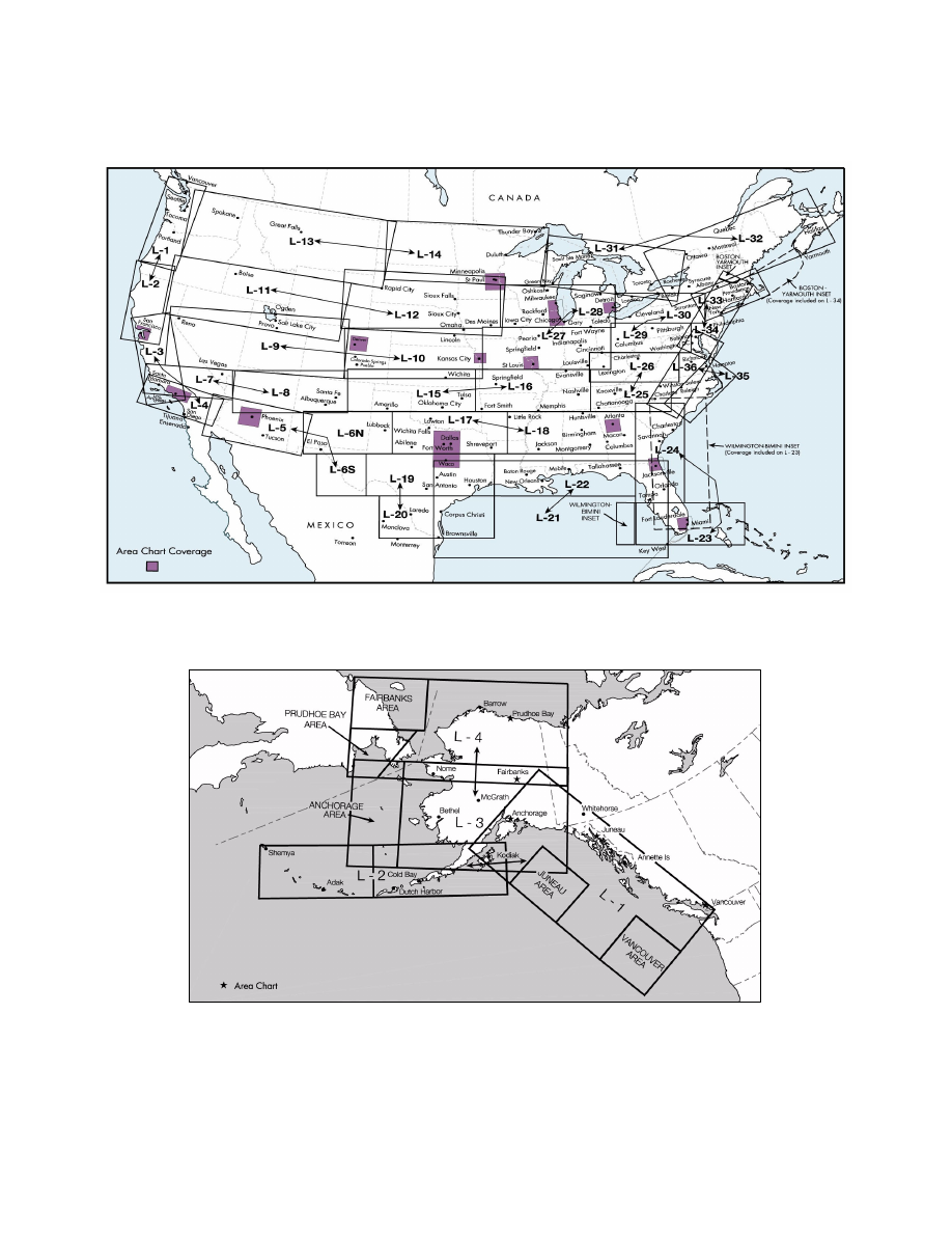
En Route Low Altitude Instrument Charts for the Conterminous U.S. (Includes Area Charts)
FIG 9
−
1
−
6
Alaska En Route Low Altitude Chart
2. IFR En Route High Altitude Charts (Conterminous U.S. and Alaska).
En route high altitude charts
are designed for navigation at or above 18,000 feet MSL. This four
−
color chart series includes the jet route
structure; VHF NAVAIDs with frequency, identification, channel, geographic coordinates; selected airports;
reporting points. Scales vary from 1 inch = 45 nm to 1 inch = 18 nm. 55 x 20 inches folded to 5 x 10 inches.
Revised every 56 days. (See FIG 9
8.)
Types of Charts Available
9
−
1
−
5